2005 NISSAN NAVARA relay
[x] Cancel search: relayPage 1651 of 3171
SERVICE INFORMATION FOR ELECTRICAL INCIDENT
GI-29
C
D
E
F
G
H
I
J
K
L
MB
GI
no voltage; short is further down the circuit than SW1.
lWith SW1 closed, relay and solenoid disconnected and the DMM leads across both fuse terminals, check
for voltage.
voltage; short is between SW1 and the relay (point B).
no voltage; short is further down the circuit than the relay.
lWith SW1 closed, relay contacts jumped with fused jumper wire check for voltage.
voltage; short is down the circuit of the relay or between the relay and the disconnected solenoid (point C).
no voltage; retrace steps and check power to fuse block.
Ground Inspection
Ground connections are very important to the proper operation of electrical and electronic circuits. Ground
connections are often exposed to moisture, dirt and other corrosive elements. The corrosion (rust) can
become an unwanted resistance. This unwanted resistance can change the way a circuit works.
Electronically controlled circuits are very sensitive to proper grounding. A loose or corroded ground can drasti-
cally affect an electronically controlled circuit. A poor or corroded ground can easily affect the circuit. Even
when the ground connection looks clean, there can be a thin film of rust on the surface.
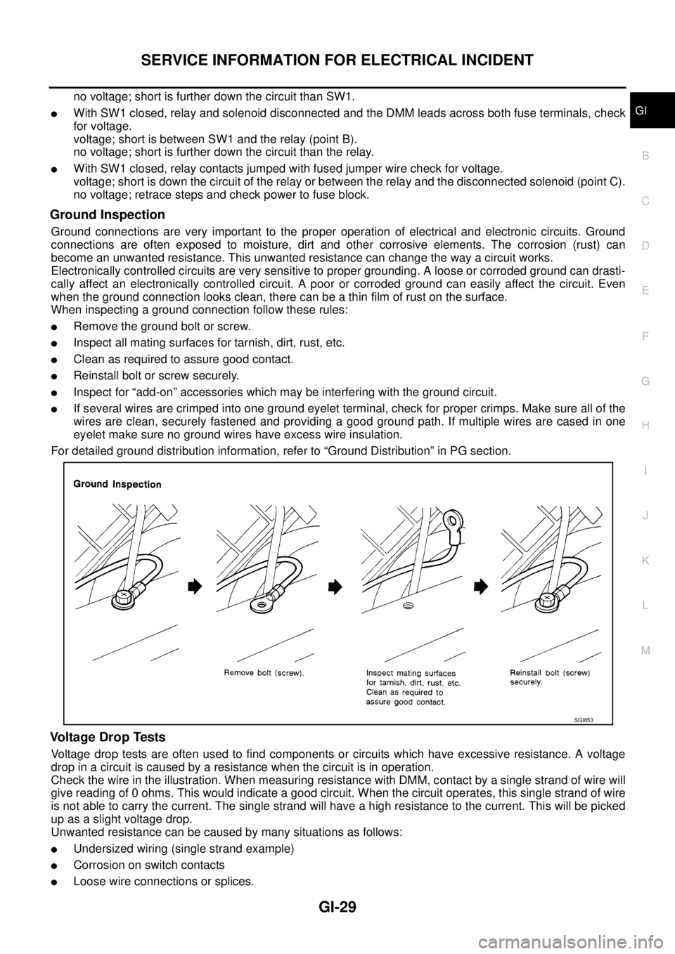
When inspecting a ground connection follow these rules:
lRemove the ground bolt or screw.
lInspect all mating surfaces for tarnish, dirt, rust, etc.
lClean as required to assure good contact.
lReinstall bolt or screw securely.
lInspect for “add-on” accessories which may be interfering with the ground circuit.
lIf several wires are crimped into one ground eyelet terminal, check for proper crimps. Make sure all of the
wires are clean, securely fastened and providing a good ground path. If multiple wires are cased in one
eyelet make sure no ground wires have excess wire insulation.
For detailed ground distribution information, refer to “Ground Distribution” in PG section.
Voltage Drop Tests
Voltage drop tests are often used to find components or circuits which have excessive resistance. A voltage
drop in a circuit is caused by a resistance when the circuit is in operation.
Check the wire in the illustration. When measuring resistance with DMM, contact by a single strand of wire will
give reading of 0 ohms. This would indicate a good circuit. When the circuit operates, this single strand of wire
is not able to carry the current. The single strand will have a high resistance to the current. This will be picked
up as a slight voltage drop.
Unwanted resistance can be caused by many situations as follows:
lUndersized wiring (single strand example)
lCorrosion on switch contacts
lLoose wire connections or splices.
SGI853
Page 1733 of 3171
REAR WINDOW DEFOGGER
GW-47
C
D
E
F
G
H
J
K
L
MA
B
GW
REAR WINDOW DEFOGGERPFP:25350
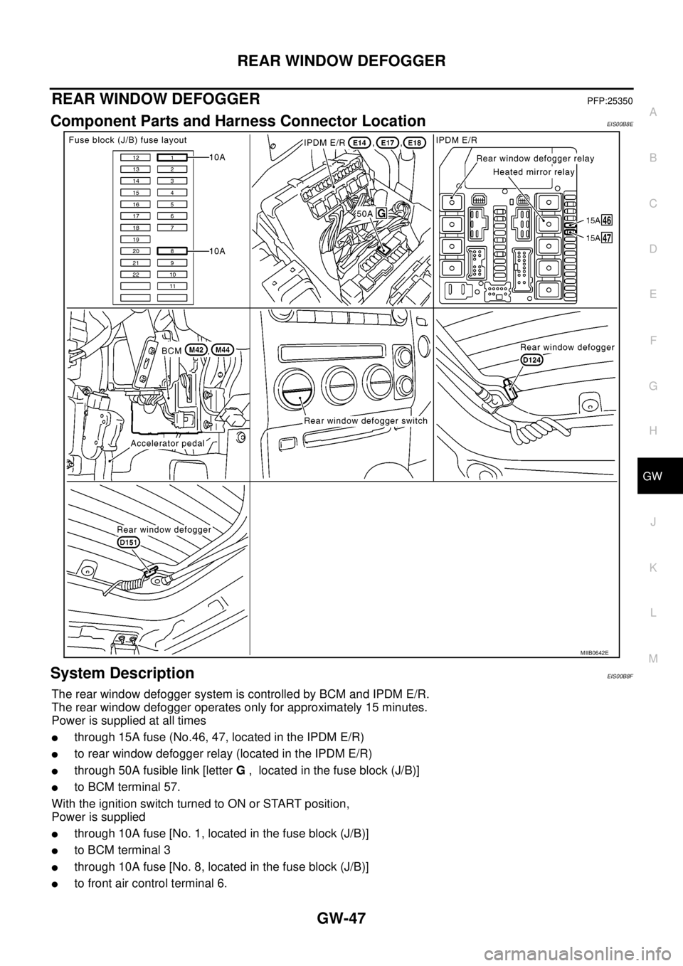
Component Parts and Harness Connector LocationEIS00B8E
System DescriptionEIS00B8F
The rear window defogger system is controlled by BCM and IPDM E/R.
The rear window defogger operates only for approximately 15 minutes.
Power is supplied at all times
lthrough 15A fuse (No.46, 47, located in the IPDM E/R)
lto rear window defogger relay (located in the IPDM E/R)
lthrough 50A fusible link [letterG, located in the fuse block (J/B)]
lto BCM terminal 57.
WiththeignitionswitchturnedtoONorSTARTposition,
Power is supplied
lthrough 10A fuse [No. 1, located in the fuse block (J/B)]
lto BCM terminal 3
lthrough 10A fuse [No. 8, located in the fuse block (J/B)]
lto front air control terminal 6.
MIIB0642E
Page 1734 of 3171
GW-48
REAR WINDOW DEFOGGER
Ground is supplied
lto BCM terminal 55
lto front air control terminal 20
lthrough body grounds M21, M80 and M83
lto IPDM E/R terminals 38 and 59
lthrough body grounds E21, E41 and E61.
When front air control (rear window defogger switch) is turned to ON,
Ground is supplied
lto BCM terminal 20
lthrough front air control terminal 11
lthrough front air control terminal 20
lthrough body grounds M21, M80 and M83.
Then rear window defogger switch is illuminated.
Then BCM recognizes that rear window defogger switch is turned to ON.
Then it sends rear window defogger switch signals to IPDM E/R via DATA LINE (CAN H, CAN L).
When display panel receives rear window defogger switch signals it illuminates on the screen.
When IPDM E/R receives rear window defogger switch signals,
Ground is supplied
lto rear window defogger relay (located in the IPDM E/R)
lthrough IPDM E/R terminals 38 and 59
lthrough body grounds E21, E41 and E61
and then rear window defogger relay and heated mirror is energized.
Power is supplied
lthrough IPDM E/R terminal 60
lto rear window defogger terminal 1.
Ground is supplied
lto rear window window defogger terminal 2
lthrough body ground D152.
With power and ground supplied, rear window defogger filaments heat and defog the rear window.
CAN Communication System DescriptionEIS00B8G
Refer toLAN-23, "CAN COMMUNICATION".
Page 1745 of 3171
REAR WINDOW DEFOGGER
GW-59
C
D
E
F
G
H
J
K
L
MA
B
GW
Rear Window Defogger Power Supply Circuit CheckEIS00B8Q
1.CHECK FUSE
lCheck 15A fuse (No.46, 47, located in the IPDM E/R)
NOTE:
Refer toGW-47, "
Component Parts and Harness Connector Location".
OK or NG
OK >> GO TO 2.
NG >> If fuse is blown, be sure to eliminate cause of malfunction before installing new fuse, refer toPG-
4, "POWER SUPPLY ROUTING CIRCUIT".
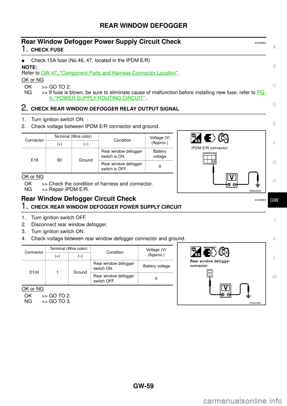
2.CHECK REAR WINDOW DEFOGGER RELAY OUTPUT SIGNAL
1. Turn ignition switch ON.
2. Check voltage between IPDM E/R connector and ground.
OK or NG
OK >> Check the condition of harness and connector.
NG >> Repair IPDM E/R.
Rear Window Defogger Circuit CheckEIS00B8R
1.CHECK REAR WINDOW DEFOGGER POWER SUPPLY CIRCUIT
1. Turn ignition switch OFF.
2. Disconnect rear window defogger.
3. Turn ignition switch ON.
4. Check voltage between rear window defogger connector and ground.
OK or NG
OK >> GO TO 2.
NG >> GO TO 3.
ConnectorTerminal (Wire color)
ConditionVoltag e (V)
(Approx.)
(+) (–)
E18 60 GroundRear window defogger
switch is ON.Battery
voltage
Rear window defogger
switch is OFF.0
MIIB0620E
ConnectorTerminal (Wire color)
ConditionVo l ta g e (V )
(Approx.)
(+) (–)
D124 1 GroundRear window defogger
switch ON.Battery voltage
Rear window defogger
switch OFF.0
PIIA4234E
Page 1755 of 3171
IDX-3
A
C
D
E
F
G
H
I
J
K
L B
IDX
ALPHABETICAL INDEX
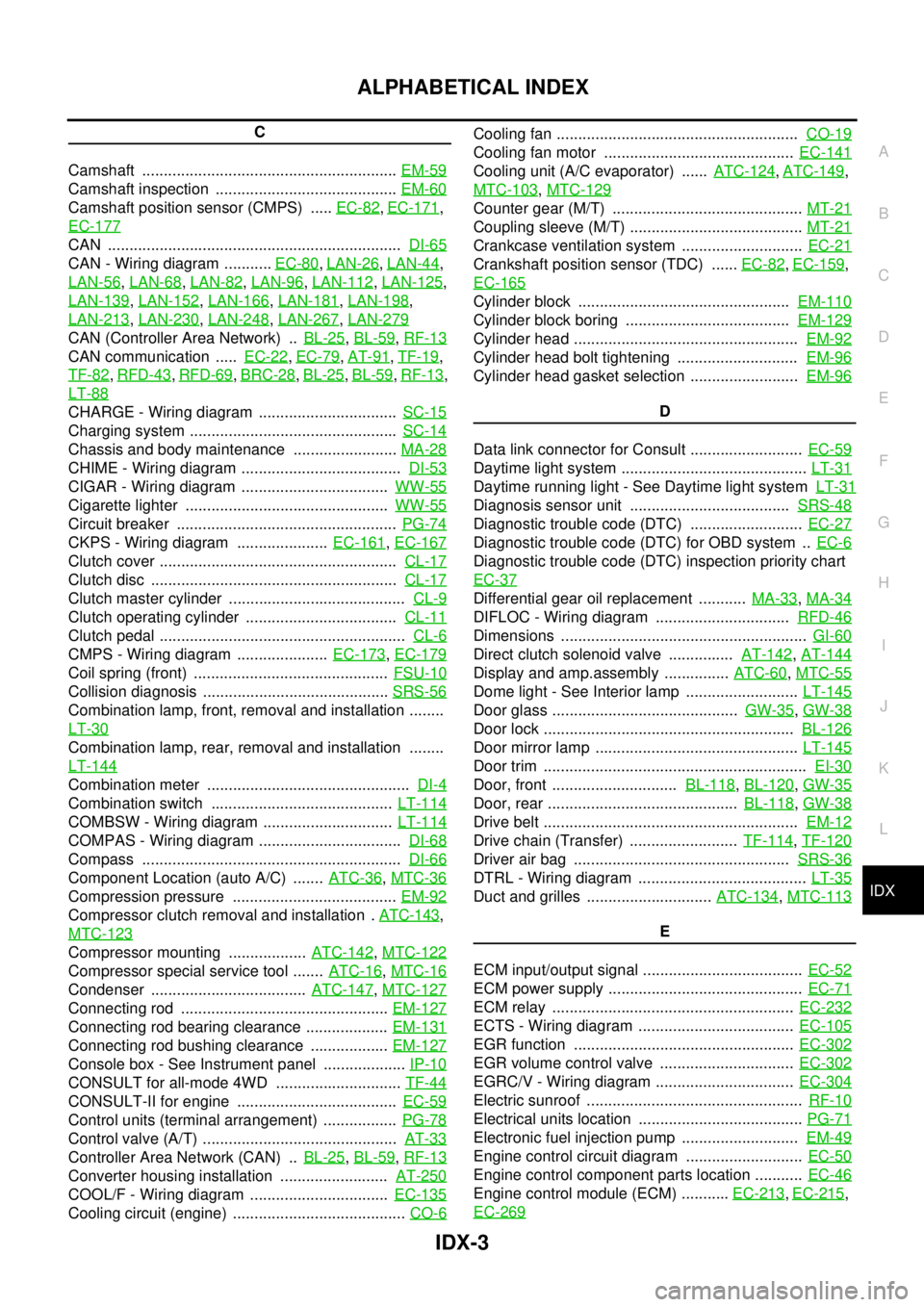
C
Camshaft ...........................................................EM-59
Camshaft inspection ..........................................EM-60
Camshaft position sensor (CMPS) .....EC-82,EC-171,
EC-177
CAN ....................................................................DI-65
CAN - Wiring diagram ...........EC-80,LAN-26,LAN-44,
LAN-56
,LAN-68,LAN-82,LAN-96,LAN-112,LAN-125,
LAN-139
,LAN-152,LAN-166,LAN-181,LAN-198,
LAN-213
,LAN-230,LAN-248,LAN-267,LAN-279
CAN (Controller Area Network) ..BL-25,BL-59,RF-13
CAN communication .....EC-22,EC-79,AT-91,TF-19,
TF-82
,RFD-43,RFD-69,BRC-28,BL-25,BL-59,RF-13,
LT-88
CHARGE - Wiring diagram ................................SC-15
Charging system ................................................SC-14
Chassis and body maintenance ........................MA-28
CHIME - Wiring diagram .....................................DI-53
CIGAR - Wiring diagram ..................................WW-55
Cigarette lighter ...............................................WW-55
Circuit breaker ...................................................PG-74
CKPS - Wiring diagram .....................EC-161,EC-167
Clutch cover .......................................................CL-17
Clutch disc .........................................................CL-17
Clutch master cylinder .........................................CL-9
Clutch operating cylinder ...................................CL-11
Clutch pedal .........................................................CL-6
CMPS - Wiring diagram .....................EC-173,EC-179
Coil spring (front) .............................................FSU-10
Collision diagnosis ...........................................SRS-56
Combination lamp, front, removal and installation ........
LT-30
Combination lamp, rear, removal and installation ........
LT-144
Combination meter ...............................................DI-4
Combination switch ..........................................LT-114
COMBSW - Wiring diagram ..............................LT-114
COMPAS - Wiring diagram .................................DI-68
Compass ............................................................DI-66
Component Location (auto A/C) .......ATC-36,MTC-36
Compression pressure ......................................EM-92
Compressor clutch removal and installation .ATC-143,
MTC-123
Compressor mounting ..................ATC-142,MTC-122
Compressor special service tool .......ATC-16,MTC-16
Condenser ....................................ATC-147,MTC-127
Connecting rod ................................................EM-127
Connecting rod bearing clearance ...................EM-131
Connecting rod bushing clearance ..................EM-127
Console box - See Instrument panel ...................IP-10
CONSULT for all-mode 4WD .............................TF-44
CONSULT-II for engine .....................................EC-59
Control units (terminal arrangement) .................PG-78
Control valve (A/T) .............................................AT-33
Controller Area Network (CAN) ..BL-25,BL-59,RF-13
Converter housing installation .........................AT-250
COOL/F - Wiring diagram ................................EC-135
Cooling circuit (engine) ........................................CO-6
Cooling fan ........................................................CO-19
Cooling fan motor ............................................EC-141
Cooling unit (A/C evaporator) ......ATC-124,ATC-149,
MTC-103
,MTC-129
Counter gear (M/T) ............................................MT-21
Coupling sleeve (M/T) ........................................MT-21
Crankcase ventilation system ............................EC-21
Crankshaft position sensor (TDC) ......EC-82,EC-159,
EC-165
Cylinder block .................................................EM-110
Cylinder block boring ......................................EM-129
Cylinder head ....................................................EM-92
Cylinder head bolt tightening ............................EM-96
Cylinder head gasket selection .........................EM-96
D
Data link connector for Consult ..........................EC-59
Daytime light system ...........................................LT-31
Daytime running light - See Daytime light systemLT-31
Diagnosis sensor unit .....................................SRS-48
Diagnostic trouble code (DTC) ..........................EC-27
Diagnostic trouble code (DTC) for OBD system ..EC-6
Diagnostic trouble code (DTC) inspection priority chart
EC-37
Differential gear oil replacement ...........MA-33,MA-34
DIFLOC - Wiring diagram ...............................RFD-46
Dimensions .........................................................GI-60
Direct clutch solenoid valve ...............AT-142,AT-144
Display and amp.assembly ...............ATC-60,MTC-55
Dome light - See Interior lamp ..........................LT-145
Door glass ...........................................GW-35,GW-38
Door lock ..........................................................BL-126
Door mirror lamp ...............................................LT-145
Door trim .............................................................EI-30
Door, front .............................BL-118,BL-120,GW-35
Door, rear ............................................BL-118,GW-38
Drive belt ...........................................................EM-12
Drive chain (Transfer) .........................TF-114,TF-120
Driver air bag ..................................................SRS-36
DTRL - Wiring diagram .......................................LT-35
Duct and grilles .............................ATC-134,MTC-113
E
ECM input/output signal .....................................EC-52
ECM power supply .............................................EC-71
ECM relay ........................................................EC-232
ECTS - Wiring diagram ....................................EC-105
EGR function ...................................................EC-302
EGR volume control valve ...............................EC-302
EGRC/V - Wiring diagram ................................EC-304
Electric sunroof ..................................................RF-10
Electrical units location ......................................PG-71
Electronic fuel injection pump ...........................EM-49
Engine control circuit diagram ...........................EC-50
Engine control component parts location ...........EC-46
Engine control module (ECM) ...........EC-213,EC-215,
EC-269
Page 1756 of 3171
IDX-4
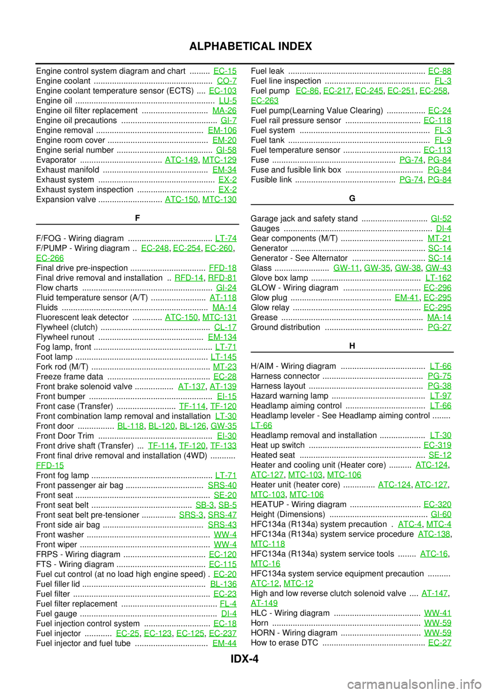
ALPHABETICAL INDEX
Engine control system diagram and chart .........EC-15
Engine coolant ....................................................CO-7
Engine coolant temperature sensor (ECTS) ....EC-103
Engine oil .............................................................LU-5
Engine oil filter replacement .............................MA-26
Engine oil precautions ..........................................GI-7
Engine removal ...............................................EM-106
Engine room cover ............................................EM-20
Engine serial number ..........................................GI-58
Evaporator ....................................ATC-149,MTC-129
Exhaust manifold ..............................................EM-34
Exhaust system ...................................................EX-2
Exhaust system inspection ..................................EX-2
Expansion valve ............................ATC-150,MTC-130
F
F/FOG - Wiring diagram .....................................LT-74
F/PUMP - Wiring diagram ..EC-248,EC-254,EC-260,
EC-266
Final drive pre-inspection .................................FFD-18
Final drive removal and installation ..RFD-14,RFD-81
Flow charts .........................................................GI-24
Fluid temperature sensor (A/T) ........................AT-118
Fluids ................................................................MA-14
Fluorescent leak detector .............ATC-150,MTC-131
Flywheel (clutch) ................................................CL-17
Flywheel runout ..............................................EM-134
Fog lamp, front ....................................................LT-71
Foot lamp ..........................................................LT-145
Fork rod (M/T) ....................................................MT-23
Freeze frame data .............................................EC-28
Front brake solenoid valve .................AT-137,AT-139
Front bumper ......................................................EI-15
Front case (Transfer) ..........................TF-114,TF-120
Front combination lamp removal and installationLT-30
Front door ................BL-118,BL-120,BL-126,GW-35
Front Door Trim ..................................................EI-30
Front drive shaft (Transfer) ...TF-114,TF-120,TF-133
Front final drive removal and installation (4WD) ...........
FFD-15
Front fog lamp .....................................................LT-71
Front passenger air bag ..................................SRS-40
Front seat ...........................................................SE-20
Front seat belt ............................................SB-3,SB-5
Front seat belt pre-tensioner ...............SRS-3,SRS-47
Front side air bag ............................................SRS-43
Front washer ......................................................WW-4
Front wiper .........................................................WW-4
FRPS - Wiring diagram ....................................EC-120
FTS - Wiring diagram .......................................EC-115
Fuel cut control (at no load high engine speed) .EC-20
Fuel filler lid ......................................................BL-136
Fuel filter ............................................................EC-23
Fuel filter replacement ..........................................FL-4
Fuel gauge ............................................................DI-4
Fuel injection control system .............................EC-18
Fuel injector ............EC-25,EC-123,EC-125,EC-237
Fuel injector and fuel tube ................................EM-44
Fuel leak ............................................................EC-88
Fuel line inspection ..............................................FL-3
Fuel pumpEC-86,EC-217,EC-245,EC-251,EC-258,
EC-263
Fuel pump(Learning Value Clearing) .................EC-24
Fuel rail pressure sensor .................................EC-118
Fuel system .........................................................FL-3
Fuel tank ..............................................................FL-9
Fuel temperature sensor ..................................EC-113
Fuse ......................................................PG-74,PG-84
Fuse and fusible link box ..................................PG-84
Fusible link ............................................PG-74,PG-84
G
Garage jack and safety stand .............................GI-52
Gauges .................................................................DI-4
Gear components (M/T) ....................................MT-21
Generator ...........................................................SC-14
Generator - See Alternator ................................SC-14
Glass ........................GW-11,GW-35,GW-38,GW-43
Glove box lamp ................................................LT-162
GLOW - Wiring diagram ..................................EC-296
Glow plug ............................................EM-41,EC-295
Glow relay ........................................................EC-295
Grease ..............................................................MA-14
Ground distribution ...........................................PG-27
H
H/AIM - Wiring diagram .....................................LT-66
Harness connector ............................................PG-75
Harness layout ..................................................PG-38
Hazard warning lamp .........................................LT-97
Headlamp aiming control ...................................LT-66
Headlamp leveler - See Headlamp aiming control ........
LT-66
Headlamp removal and installation ....................LT-30
Heat up switch .................................................EC-319
Heated seat .......................................................SE-12
Heater and cooling unit (Heater core) ..........ATC-124,
ATC-127
,MTC-103,MTC-106
Heater unit (heater core) ..............ATC-124,ATC-127,
MTC-103
,MTC-106
HEATUP - Wiring diagram ...............................EC-320
Height (Dimensions) ...........................................GI-60
HFC134a (R134a) system precaution .ATC-4,MTC-4
HFC134a (R134a) system service procedureATC-138,
MTC-118
HFC134a (R134a) system service tools ........ATC-16,
MTC-16
HFC134a system service equipment precaution ..........
ATC-12
,MTC-12
High and low reverse clutch solenoid valve ....AT-147,
AT-149
HLC - Wiring diagram ......................................WW-41
Horn .................................................................WW-59
HORN - Wiring diagram ...................................WW-59
How to erase DTC .............................................EC-27
Page 1758 of 3171
IDX-6
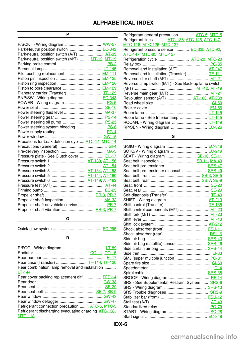
ALPHABETICAL INDEX
P
P/SCKT - Wiring diagram ................................WW-57
Park/Neutral position switch ............................EC-342
Park/neutral position switch (A/T) ......................AT-99
Park/neutral position switch (M/T) ........MT-12,MT-19
Parking brake control ...........................................PB-2
Personal lamp ...................................................LT-145
Pilot bushing replacement ..............................EM-111
Piston pin inspection .......................................EM-125
Piston ring inspection ......................................EM-126
Piston to bore clearance .................................EM-129
Planetary carrier (Transfer) ..............................TF-129
PNP/SW - Wiring diagram ...............................EC-343
POWER - Wiring diagram ....................................PG-5
Power seat .........................................................SE-10
Power steering fluid level ..................................MA-37
Power steering gear ...........................................PS-14
Power steering oil pump ....................................PS-25
Power steering system bleeding ..........................PS-6
Power supply routing ...........................................PG-4
Power window ...................................................GW-15
Precations for Leak detection dye ....ATC-14,MTC-14
Precautions (General) ...........................................GI-4
Pre-delivery inspection .......................................MA-5
Pressure plate - See Clutch cover .....................CL-17
Pressure switch 1 ..............................AT-139,AT-156
Pressure switch 2 ............................................AT-154
Pressure switch 3 ..............................AT-134,AT-158
Pressure switch 5 ..............................AT-144,AT-160
Pressure switch 6 ..............................AT-149,AT-162
Pressure test (A/T) .............................................AT-44
Priming pump .....................................................EC-23
Propeller shaft ............................................PR-3,PR-7
Propeller shaft inspection .................................MA-32
Propeller shaft on vehicle service ........................PR-7
Propeller shaft vibration .............................PR-3,PR-7
Q
Quick-glow system ...........................................EC-295
R
R/FOG - Wiring diagram .....................................LT-89
Radiator ................................................CO-11,CO-15
Rear bumper .......................................................EI-17
Rear case (Transfer) ...........................TF-114,TF-120
Rear combination lamp removal and installation ..........
LT-144
Rear cover packing replacement diff. ..............FFD-14
Rear door ..........................................................GW-38
Rear seat ...........................................................SE-29
Rear seat belt ............................................SB-7,SB-9
Rear window .....................................................GW-43
Rear window defogger ......................................GW-47
Refrigerant connection precaution ........ATC-5,MTC-5
Refrigerant discharging evacuating chargingATC-138,
MTC-118
Refrigerant general precaution ............ATC-5,MTC-5
Refrigerant lines ...........ATC-138,ATC-146,ATC-147,
MTC-118
,MTC-126,MTC-127
Refrigerant pressure sensor ............EC-325,ATC-92,
ATC-147
,MTC-85,MTC-127
Refrigeration cycle ...........................ATC-20,MTC-20
Relay box ..........................................................PG-85
Removal and installation (A/T) .........................AT-247
Removal and installation (Transfer) .................TF-111
Reverse idler shaft (M/T) ..................................MT-21
Reverse lamp switch (M/T) - See Back-up lamp switch
(M/T) .....................................................MT-12
,MT-19
Reverse main gear (M/T) ..................................MT-21
Revolution sensor (A/T) .....................AT-103,AT-238
Road wheel size .................................................GI-60
Rocker cover .....................................................EM-56
Room lamp ......................................................LT-145
Room lamp - See Interior lamp ........................LT-145
ROOM/L - Wiring diagram ...............................LT-149
RP/SEN - Wiring diagram ................................EC-326
S
S/SIG - Wiring diagram ....................................EC-348
SCTC/V - Wiring diagram ................................EC-219
SEAT - Wiring diagram ..........................SE-10,SE-11
Seat belt inspection ..............................SB-11,MA-40
Seat belt pre-tensioner ...................................SRS-47
Seat belt pre-tensioner disposal .....................SRS-49
Seat belt, front ...........................................SB-3,SB-5
Seat belt, rear ............................................SB-7,SB-9
Seat, front ..........................................................SE-20
Seat, rear ...........................................................SE-29
Self-diagnosis (Transfer) ...................................TF-49
SHIFT - Wiring diagram ...................................AT-213
Shift control (Transfer) .....................................TF-135
Shift control components (M/T) .........................MT-23
Shift fork (M/T) ..................................................MT-23
Shift lever ..........................................................MT-13
Shift lock system ..............................................AT-212
Shock absorber (front) ....................................FSU-11
Shock absorber (rear) .......................................RSU-6
Side air bag .....................................................SRS-43
Side air bag (satellite) sensor .........................SRS-46
Side curtain air bag .........................................SRS-44
Side trim ..............................................................EI-33
SMJ (super multiple junction) ...........................PG-81
Spare tire size .....................................................GI-60
Speedometer ........................................................DI-4
Spiral cable .....................................................SRS-38
SROOF - Wiring diagram ...................................RF-14
SRS - See Supplemental Restraint System .....SRS-6
SRS - Wiring diagram .....................................SRS-13
SRS Trouble diagnoses ....................................SRS-9
Stabilizer bar (front) ........................................FSU-12
Stall test (A/T) ....................................................AT-43
Standardized relay ............................................PG-79
START - Wiring diagram ....................................SC-28
Start signal .......................................................EC-348
Page 1779 of 3171

LAN-2
Wiring Diagram — CAN — ..................................... 82
Check Sheet ........................................................... 83
CHECK SHEET RESULTS (EXAMPLE) ............. 85
CAN SYSTEM (TYPE 5) ........................................... 96
Component Parts and Harness Connector Location... 96
Schematic ............................................................... 96
Wiring Diagram — CAN — ..................................... 96
Check Sheet ........................................................... 97
CHECK SHEET RESULTS (EXAMPLE) ............. 99
CAN SYSTEM (TYPE 6) .........................................112
Component Parts and Harness Connector Location.112
Schematic .............................................................112
Wiring Diagram — CAN — ...................................112
Check Sheet .........................................................113
CHECK SHEET RESULTS (EXAMPLE) ...........115
CAN SYSTEM (TYPE 7) .........................................125
Component Parts and Harness Connector Location.125
Schematic .............................................................125
Wiring Diagram — CAN — ...................................125
Check Sheet .........................................................126
CHECK SHEET RESULTS (EXAMPLE) ...........128
CAN SYSTEM (TYPE 8) .........................................139
Component Parts and Harness Connector Location.139
Schematic .............................................................139
Wiring Diagram — CAN — ...................................139
Check Sheet .........................................................140
CHECK SHEET RESULTS (EXAMPLE) ...........142
CAN SYSTEM (TYPE 9) .........................................152
Component Parts and Harness Connector Location.152
Schematic .............................................................152
Wiring Diagram — CAN — ...................................152
Check Sheet .........................................................153
CHECK SHEET RESULTS (EXAMPLE) ...........155
CAN SYSTEM (TYPE 10) .......................................166
Component Parts and Harness Connector Location.166
Schematic .............................................................166
Wiring Diagram — CAN — ...................................166
Check Sheet .........................................................167
CHECK SHEET RESULTS (EXAMPLE) ...........169
CAN SYSTEM (TYPE 11) ........................................181
Component Parts and Harness Connector Location.181
Schematic .............................................................181
Wiring Diagram — CAN — ...................................181
Check Sheet .........................................................182
CHECK SHEET RESULTS (EXAMPLE) ...........185
CAN SYSTEM (TYPE 12) .......................................198
Component Parts and Harness Connector Location.198
Schematic .............................................................198
Wiring Diagram — CAN — ...................................198
Check Sheet .........................................................199
CHECK SHEET RESULTS (EXAMPLE) ...........201
CAN SYSTEM (TYPE 13) .......................................213
Component Parts and Harness Connector Location.213Schematic .............................................................213
Wiring Diagram — CAN — ...................................213
Check Sheet .........................................................214
CHECK SHEET RESULTS (EXAMPLE) ............217
CAN SYSTEM (TYPE 14) ........................................230
Component Parts and Harness Connector Location.230
Schematic .............................................................230
Wiring Diagram — CAN — ...................................230
Check Sheet .........................................................231
CHECK SHEET RESULTS (EXAMPLE) ............234
CAN SYSTEM (TYPE 15) ........................................248
Component Parts and Harness Connector Location.248
Schematic .............................................................248
Wiring Diagram — CAN — ...................................248
Check Sheet .........................................................249
CHECK SHEET RESULTS (EXAMPLE) ............252
CAN SYSTEM (TYPE 16) ........................................267
Component Parts and Harness Connector Location.267
Schematic .............................................................267
Wiring Diagram — CAN — ...................................267
Check Sheet .........................................................268
CHECK SHEET RESULTS (EXAMPLE) ............270
CAN SYSTEM (TYPE 17) ........................................279
Component Parts and Harness Connector Location.279
Schematic .............................................................279
Wiring Diagram — CAN — ...................................279
Check Sheet .........................................................280
CHECK SHEET RESULTS (EXAMPLE) ............282
TROUBLE DIAGNOSIS FOR SYSTEM ..................292
Inspection Between TCM and Data Link Connector
Circuit ....................................................................292
Inspection Between TCM and NAVI Control Unit Cir-
cuit ........................................................................293
Inspection Between NAVI Control Unit and Data
Link Connector Circuit ...........................................295
Inspection Between Data Link Connector and ABS
Actuator and Electric Unit (Control Unit) Circuit ....296
ECM Circuit Inspection for M/T Models ................297
ECM Circuit Inspection for A/T Models .................298
TCM Circuit Inspection ..........................................298
NAVI Control Unit Circuit Inspection .....................299
Differential Lock Control Unit Circuit Inspection ....299
Front Air Control Circuit Inspection .......................300
Data Link Connector Circuit Inspection .................300
BCM Circuit Inspection .........................................301
Combination Meter Circuit Inspection ...................301
Transfer Control Unit Circuit Inspection ................302
ABS Actuator and Electric Unit (Control Unit) Circuit
Inspection ..............................................................302
IPDM E/R Circuit Inspection .................................303
CAN Communication Circuit Inspection ................303
IPDM E/R Ignition Relay Circuit Inspection ...........304