2005 NISSAN NAVARA relay
[x] Cancel search: relayPage 2100 of 3171

HEADLAMP -CONVENTIONAL TYPE-
LT-17
C
D
E
F
G
H
I
J
L
MA
B
LT
NOTE:
This item is displayed, but cannot be monitored.
ACTIVE TEST
Operation Procedure
1. Touch “HEADLAMP” on “SELECT TEST ITEM” screen.
2. Touch “ACTIVE TEST” on “SELECT DIAG MODE” screen.
3. Touch item to be tested and check operation of the selected item.
4. During the operation check, touching “OFF” deactivates the operation.
Display Item List
HEAD LAMP SW 1 “ON/OFF”Displays status (lighting switch 2ND position: ON/other: OFF) of headlamp 1 switch judged
from the lighting switch signal.
HEAD LAMP SW 2 “ON/OFF”Displays status (lighting switch 2ND position: ON/other: OFF) of headlamp 2 switch judged
from the lighting switch signal.
LIGHT SW 1ST “ON/OFF”Displays status (lighting switch 1ST or 2ND position: ON/other: OFF) of lighting switch 1ST
position switch judged from the lighting switch signal.
PASSING SW “ON/OFF”Displays status (lighting switch passing position: ON/other: OFF) of passing switch judged
from the lighting switch signal.
FR FOG SW “ON/OFF”Displays status (lighting switch front fog lamp ON position: ON/others: OFF) of front fog lamp
switch judged from the lighting switch signal.
RR FOG SW “ON/OFF”Displays status (lighting switch rear fog lamp ON position: ON/others: OFF) of rear fog lamp
switch judged from the lighting switch signal.
DOOR SW - DR “ON/OFF”Displays status (door is open: ON/door is closed: OFF) of driver side door switch judged from
the driver side door switch signal.
DOOR SW - AS “ON/OFF”Displays status (door is open: ON/door is closed: OFF) of passenger side door switch judged
from the passenger side door switch signal.
DOOR SW - RR “ON/OFF”Displays status (door is open: ON/door is closed: OFF) of rear door switch (RH) judged from
the rear door switch (RH) signal.
DOOR SW - RL “ON/OFF”Displays status (door is open: ON/door is closed: OFF) of rear door switch (LH) judged from
the rear door switch (LH) signal.
BACK DOOR SW “ON/OFF”Displays status (door is open: ON/door is closed: OFF) of back door switch judged from the
back door switch signal.
TURN SIGNAL R “ON/OFF”Displays status (turn signal switch right position: ON/other: OFF) of turn RH switch judged
from the turn signal switch signal.
TURN SIGNAL L “ON/OFF”Displays status (turn signal switch left position: ON/other: OFF) of turn LH switch judged from
the turn signal switch signal.
CARGO LAMP SW
NOTE“OFF” —
HD LIGHT TIMER“10 sec/
30 sec”Displays status (MODE 1: 10 sec./ MODE 2: 30 sec.) of head light timer.
LIT-SEN FAIL
NOTE“OK” —
AUT LIGHT SYS
NOTE“OFF” — Monitor item Contents
Test item Description
TAIL LAMP Allows tail lamp relay to operate by switching ON–OFF.
HEAD LAMP (HI, LO) Allows headlamp relay to operate by switching ON-OFF.
RR FOG LAMP Allows rear fog lamp to operate by switching ON–OFF.
FR FOG LAMP Allows front fog lamp relay to operate by switching ON–OFF.
Page 2103 of 3171

LT-20
HEADLAMP -CONVENTIONAL TYPE-
Headlamp High Beam Does Not Illuminate (Both Sides)
EKS00P7S
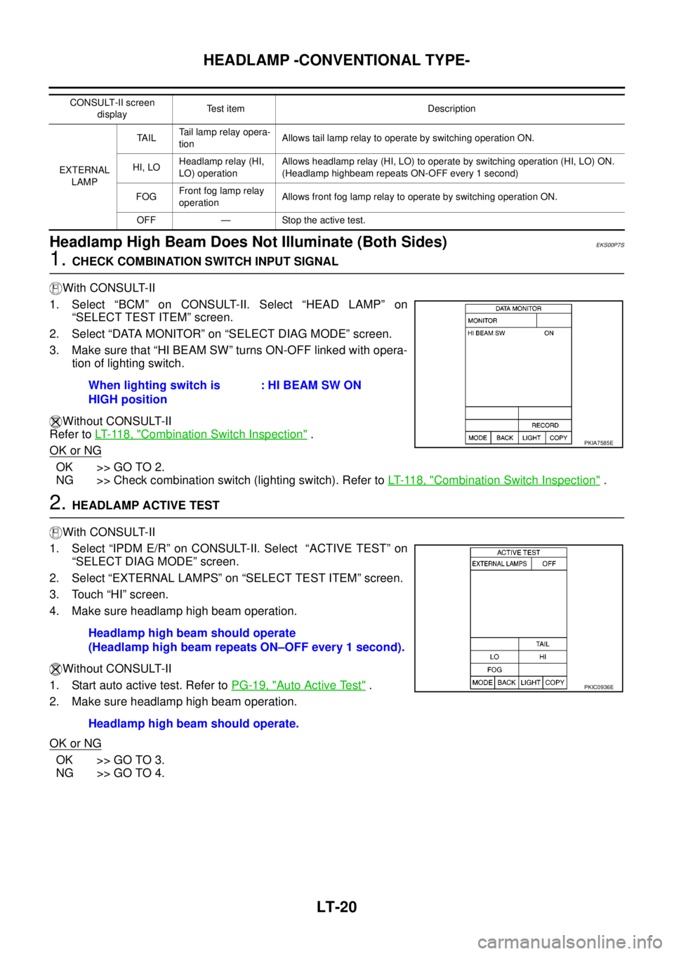
1.CHECK COMBINATION SWITCH INPUT SIGNAL
With CONSULT-II
1. Select “BCM” on CONSULT-II. Select “HEAD LAMP” on
“SELECT TEST ITEM” screen.
2. Select “DATA MONITOR” on “SELECT DIAG MODE” screen.
3. Make sure that “HI BEAM SW” turns ON-OFF linked with opera-
tion of lighting switch.
Without CONSULT-II
Refer toLT- 11 8 , "
Combination Switch Inspection".
OK or NG
OK >> GO TO 2.
NG >> Check combination switch (lighting switch). Refer toLT- 11 8 , "
Combination Switch Inspection".
2.HEADLAMP ACTIVE TEST
With CONSULT-II
1. Select “IPDM E/R” on CONSULT-II. Select “ACTIVE TEST” on
“SELECT DIAG MODE” screen.
2. Select “EXTERNAL LAMPS” on “SELECT TEST ITEM” screen.
3. Touch “HI” screen.
4. Make sure headlamp high beam operation.
Without CONSULT-II
1. Start auto active test. Refer toPG-19, "
Auto Active Test".
2. Make sure headlamp high beam operation.
OK or NG
OK >> GO TO 3.
NG >> GO TO 4.
CONSULT-II screen
displayTest item Description
EXTERNAL
LAMPTA I LTail lamp relay opera-
tionAllows tail lamp relay to operate by switching operation ON.
HI, LOHeadlamp relay (HI,
LO) operationAllows headlamp relay (HI, LO) to operate by switching operation (HI, LO) ON.
(Headlamp highbeam repeats ON-OFF every 1 second)
FOGFront fog lamp relay
operationAllows front fog lamp relay to operate by switching operation ON.
OFF — Stop the active test.
When lighting switch is
HIGH position: HI BEAM SW ON
PKIA7585E
Headlamp high beam should operate
(Headlamp high beam repeats ON–OFF every 1 second).
Headlamp high beam should operate.
PKIC0936E
Page 2114 of 3171

HEADLAMP - DAYTIME LIGHT SYSTEM -
LT-31
C
D
E
F
G
H
I
J
L
MA
B
LT
HEADLAMP - DAYTIME LIGHT SYSTEM -PFP:26010
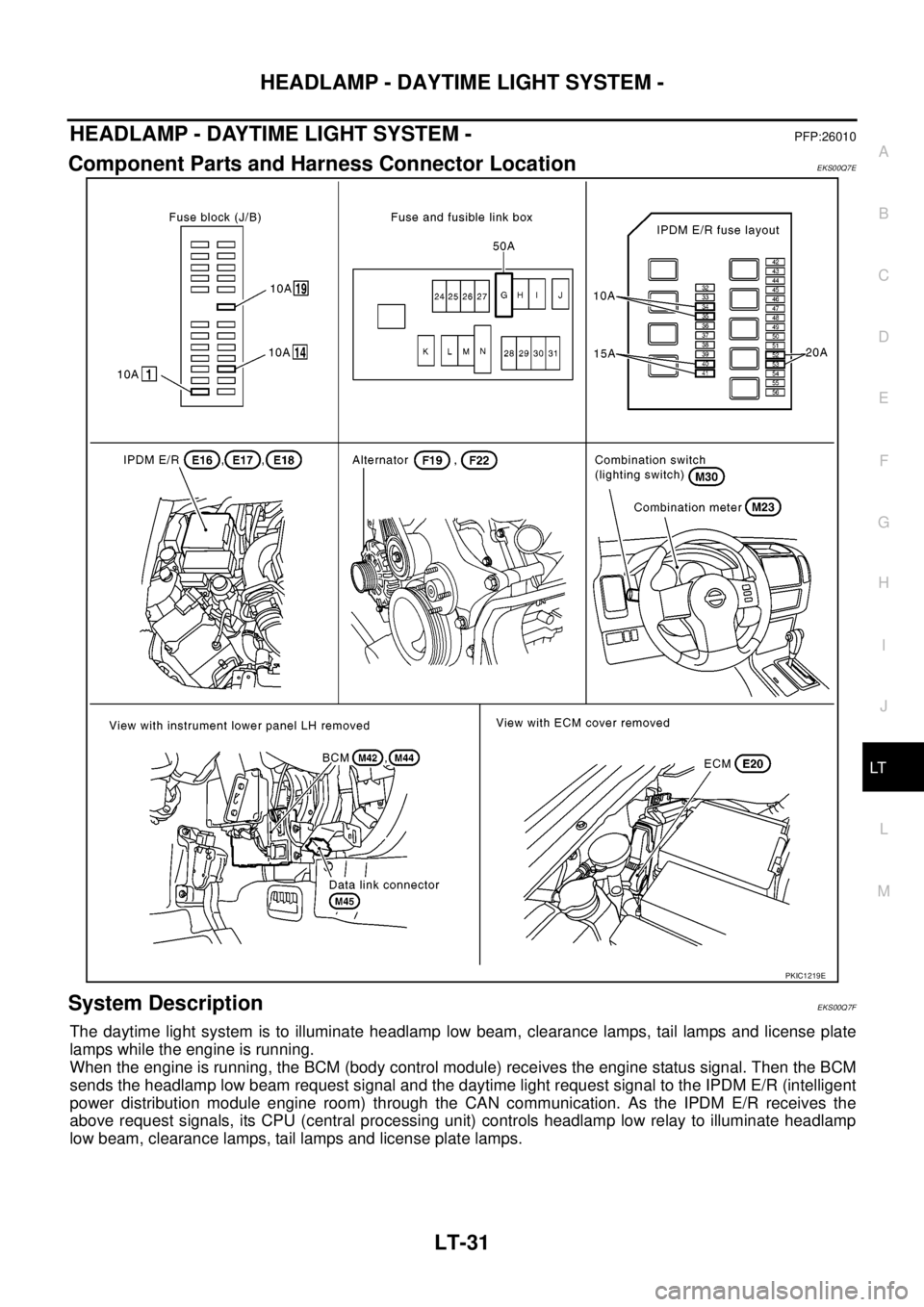
Component Parts and Harness Connector LocationEKS00Q7E
System DescriptionEKS00Q7F
The daytime light system is to illuminate headlamp low beam, clearance lamps, tail lamps and license plate
lamps while the engine is running.
When the engine is running, the BCM (body control module) receives the engine status signal. Then the BCM
sends the headlamp low beam request signal and the daytime light request signal to the IPDM E/R (intelligent
power distribution module engine room) through the CAN communication. As the IPDM E/R receives the
above request signals, its CPU (central processing unit) controls headlamp low relay to illuminate headlamp
low beam, clearance lamps, tail lamps and license plate lamps.
PKIC1219E
Page 2115 of 3171

LT-32
HEADLAMP - DAYTIME LIGHT SYSTEM -
OUTLINE
Power is supplied at all times
lto ignition relay (located in IPDM E/R)
lto headlamp high relay (located in IPDM E/R) and
lto headlamp low relay (located in IPDM E/R), from battery directly,
lthrough 50A fusible link (letter G, located in fuse and fusible link box)
lto BCM terminal 57,
lthrough 20A fuse (No. 52, located in IPDM E/R) and
lthrough 20A fuse (No. 53, located in IPDM E/R)
lto CPU (located in IPDM E/R),
lthrough 10A fuse [No. 19, located in fuse block (J/B)]
lto combination meter terminal 3.
With the ignition switch in the ON or START position, power is supplied
lto ignition relay (located in IPDM E/R),
lthrough 10A fuse [No. 1, located in fuse block (J/B)]
lto BCM terminal 3,
lthrough 10A fuse [No. 14, located in fuse block (J/B)]
lto combination meter terminal 16.
Ground is supplied at all times
lto BCM terminal 55 and
lto combination meter terminal 23
lthrough grounds M21, M80 and M83,
lto IPDM E/R terminals 38 and 59
lthrough grounds E21, E41 and E61.
DAYTIME LIGHT OPERATION
With the lighting switch in the OFF position and engine running, the BCM receives input signal requesting
headlamp low beam, clearance lamp, license plate lamp, and tail lamp to illuminate. This input signal is com-
municated to the IPDM E/R through the CAN communication. The CPU located in the IPDM E/R controls
headlamp low relay.
lthrough 15A fuse (No. 41, located in IPDM E/R)
lthrough IPDM E/R terminal 54
lto front combination lamp RH terminal 1,
lthrough 15A fuse (No. 40, located in IPDM E/R)
lthrough IPDM E/R terminal 52
lto front combination lamp LH terminal 1.
Ground is supplied at all times
lto front combination lamp RH and LH terminals 3
lthrough grounds E21, E41 and E61.
With power and ground supplied, the headlamp low beam, clearance, license plate and tail lamps illuminate.
Page 2127 of 3171

LT-44
HEADLAMP - DAYTIME LIGHT SYSTEM -
NOTE:
This item is displayed, but cannot be monitored.
ACTIVE TEST
Operation Procedure
1. Touch “HEAD LAMP” on “SELECT TEST ITEM” screen.
2. Touch “ACTIVE TEST” on “SELECT DIAG MODE” screen.
3. Touch item to be tested and check operation of the selected item.
4. During the operation check, touching “OFF” deactivates the operation.
Display Item List
BACK DOOR SW “ON/OFF”Displays status (door is open: ON/door is closed: OFF) of back door switch judged from the
back door switch signal.
TURN SIGNAL R “ON/OFF”Displays status (turn signal switch right position: ON/other: OFF) of turn RH switch judged
from the turn signal switch signal.
TURN SIGNAL L “ON/OFF”Displays status (turn signal switch left position: ON/other: OFF) of turn LH switch judged from
the turn signal switch signal.
CARGO LAMP SW
NOTE“OFF” —
HD LIGHT TIMER“10 sec/
30 sec”Displays status (MODE 1: 10 sec./ MODE 2: 30 sec.) of head light timer.
LIT-SEN FAIL
NOTE“OK” —
AUT LIGHT SYS
NOTE“OFF” — Monitor item Contents
Test item Description
TAIL LAMP Allows tail lamp relay to operate by switching ON–OFF.
HEAD LAMP (HI, LO) Allows headlamp relay to operate by switching ON-OFF.
RR FOG LAMP Allows rear fog lam to operate by switching ON–OFF.
FR FOG LAMP Allows front fog lamp relay to operate by switching ON–OFF.
DAYTIME RUNNING LIGHT Allows daytime running light lamp operate by switching ON–OFF.
Page 2130 of 3171

HEADLAMP - DAYTIME LIGHT SYSTEM -
LT-47
C
D
E
F
G
H
I
J
L
MA
B
LT
Daytime Light Control Does Not Operate Properly (Normal Headlamps Operate
Properly)
EKS00Q7Q
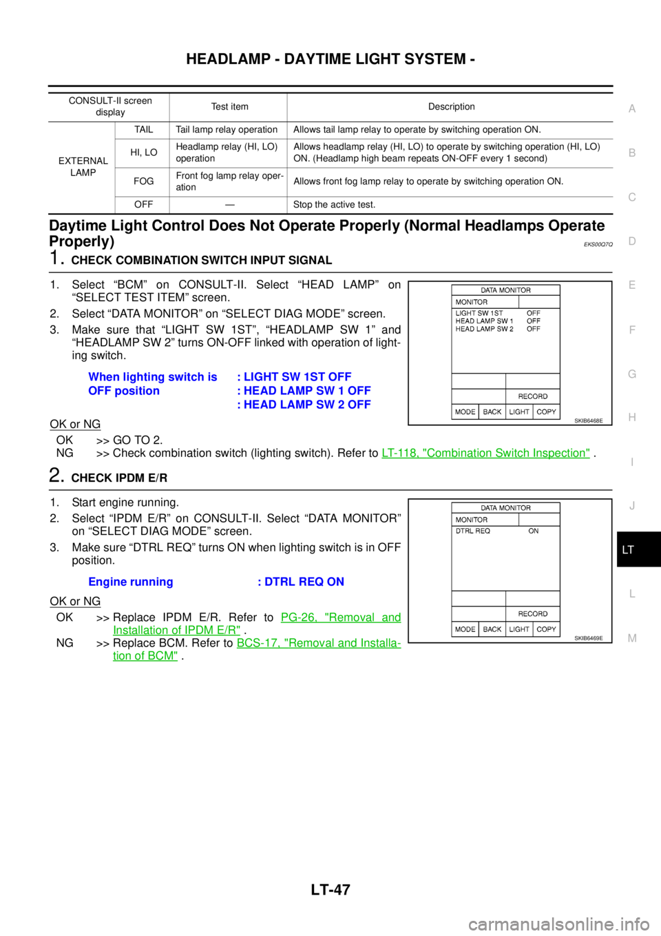
1.CHECK COMBINATION SWITCH INPUT SIGNAL
1. Select “BCM” on CONSULT-II. Select “HEAD LAMP” on
“SELECT TEST ITEM” screen.
2. Select “DATA MONITOR” on “SELECT DIAG MODE” screen.
3. Make sure that “LIGHT SW 1ST”, “HEADLAMP SW 1” and
“HEADLAMP SW 2” turns ON-OFF linked with operation of light-
ing switch.
OK or NG
OK >> GO TO 2.
NG >> Check combination switch (lighting switch). Refer toLT- 11 8 , "
Combination Switch Inspection".
2.CHECK IPDM E/R
1. Start engine running.
2. Select “IPDM E/R” on CONSULT-II. Select “DATA MONITOR”
on “SELECT DIAG MODE” screen.
3. Make sure “DTRL REQ” turns ON when lighting switch is in OFF
position.
OK or NG
OK >> Replace IPDM E/R. Refer toPG-26, "Removal and
Installation of IPDM E/R".
NG >> Replace BCM. Refer toBCS-17, "
Removal and Installa-
tion of BCM".
CONSULT-II screen
displayTest item Description
EXTERNAL
LAMPTAIL Tail lamp relay operation Allows tail lamp relay to operate by switching operation ON.
HI, LOHeadlamp relay (HI, LO)
operationAllows headlamp relay (HI, LO) to operate by switching operation (HI, LO)
ON. (Headlamp high beam repeats ON-OFF every 1 second)
FOGFront fog lamp relay oper-
ationAllows front fog lamp relay to operate by switching operation ON.
OFF — Stoptheactivetest.
When lighting switch is
OFF position:LIGHTSW1STOFF
: HEAD LAMP SW 1 OFF
: HEAD LAMP SW 2 OFF
SKIB6468E
Engine running : DTRL REQ ON
SKIB6469E
Page 2140 of 3171

AUTO LIGHT SYSTEM
LT-57
C
D
E
F
G
H
I
J
L
MA
B
LT
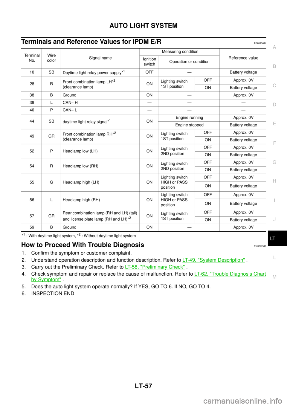
Terminals and Reference Values for IPDM E/REKS00Q82
*1: With daytime light system, *2: Without daytime light system
How to Proceed With Trouble DiagnosisEKS00Q83
1. Confirm the symptom or customer complaint.
2. Understand operation description and function description. Refer toLT-49, "
System Description".
3. Carry out the Preliminary Check. Refer toLT-58, "
Preliminary Check".
4. Check symptom and repair or replace the cause of malfunction. Refer toLT-62, "
Trouble Diagnosis Chart
by Symptom".
5. Does the auto light system operate normally? If YES, GO TO 6. If NO, GO TO 4.
6. INSPECTION END
Terminal
No.Wire
colorSignal nameMeasuring condition
Reference value
Ignition
switchOperation or condition
10 SB
Daytime light relay power supply*
1OFF — Battery voltage
28 RFront combination lamp LH*
2
(clearance lamp)ONLighting switch
1ST positionOFF Approx. 0V
ON Battery voltage
38 B Ground ON — Approx. 0V
39 L CAN-H———
40 P CAN-L———
44 SB
daytime light relay signal*
1ONEngine running Approx. 0V
Engine stopped Battery voltage
49 GRFront combination lamp RH*
2
(clearance lamp)ONLighting switch
1ST positionOFF Approx. 0V
ON Battery voltage
52 P Headlamp low (LH) ONLighting switch
2ND positionOFF Approx. 0V
ON Battery voltage
54 R Headlamp low (RH) ONLighting switch
2ND positionOFF Approx. 0V
ON Battery voltage
55 G Headlamp high (LH) ONLighting switch
HIGH or PASS
positionOFF Approx. 0V
ON Battery voltage
56 L Headlamp high (RH) ONLighting switch
HIGH or PASS
positionOFF Approx. 0V
ON Battery voltage
57 GRRear combination lamp (RH and LH) (tail)
and license plate lamp (RH and LH)*
2ONLighting switch
1ST positionOFF Approx. 0V
ON Battery voltage
59 B Ground ON — Approx. 0V
Page 2144 of 3171

AUTO LIGHT SYSTEM
LT-61
C
D
E
F
G
H
I
J
L
MA
B
LT
Display Item List
NOTE:
This item is displayed, but cannot be monitored.
ACTIVE TEST
Operation Procedure
1. Touch “HEAD LAMP” on “SELECT TEST ITEM” screen.
2. Touch “ACTIVE TEST” on “SELECT DIAG MODE” screen.
3. Touch item to be tested and check operation of the selected item.
4. During the operation check, touching “OFF” deactivates the operation.
Display Item List
Monitor item Contents
IGN ON SW “ON/OFF”Displays status (ignition switch IGN position: ON/other: OFF) of ignition switch judged from
the ignition switch signal.
ACC ON SW “ON/OFF”Displays status (ignition switch ACC or IGN position: ON/other: OFF) of ignition switch judged
from the ignition switch signal.
HI BEAM SW “ON/OFF”Displays status (lighting switch high beam position: ON/other: OFF) of high beam switch
judged from the lighting switch signal.
HEAD LAMP SW 1 “ON/OFF”Displays status (lighting switch 2ND position: ON/other: OFF) of headlamp 1 switch judged
from the lighting switch signal.
HEAD LAMP SW 2 “ON/OFF”Displays status (lighting switch 2ND position: ON/other: OFF) of headlamp 2 switch judged
from the lighting switch signal.
LIGHT SW 1ST “ON/OFF”Displays status (lighting switch 1ST or 2ND position: ON/other: OFF) of lighting switch 1ST
position switch judged from the lighting switch signal.
PASSING SW “ON/OFF”Displays status (lighting switch passing position: ON/other: OFF) of passing switch judged
from the lighting switch signal.
FR FOG SW “ON/OFF”Displays status (lighting switch front fog lamp ON position: ON/others: OFF) of front fog lamp
switch judged from the lighting switch signal.
RR FOG SW “ON/OFF”Displays status (lighting switch rear fog lamp ON position: ON/others: OFF) of rear fog lamp
switch judged from the lighting switch signal.
DOOR SW - DR “ON/OFF”Displays status (door is open: ON/door is closed: OFF) of driver side door switch judged from
the driver side door switch signal.
DOOR SW - AS “ON/OFF”Displays status (door is open: ON/door is closed: OFF) of passenger side door switch judged
from the passenger side door switch signal.
DOOR SW - RR “ON/OFF”Displays status (door is open: ON/door is closed: OFF) of rear door switch (RH) judged from
the rear door switch (RH) signal.
DOOR SW - RL “ON/OFF”Displays status (door is open: ON/door is closed: OFF) of rear door switch (LH) judged from
the rear door switch (LH) signal.
BACK DOOR SW “ON/OFF”Displays status (door is open: ON/door is closed: OFF) of back door switch judged from the
back door switch signal.
TURN SIGNAL R “ON/OFF”Displays status (turn signal switch right position: ON/other: OFF) of turn RH switch judged
from the turn signal switch signal.
TURN SIGNAL L “ON/OFF”Displays status (turn signal switch left position: ON/other: OFF) of turn LH switch judged from
the turn signal switch signal.
CARGO LAMP SW
NOTE“OFF” —
HD LIGHT TIMER“10 sec/
30 sec”Displays status (MODE 1: 10 sec./ MODE 2: 30 sec.) of head light timer.
LIT-SEN FAIL
NOTE“OK” —
AUT LIGHT SYS
NOTE“OFF” —
Test item Description
TAIL LAMP Allows tail lamp relay to operate by switching ON-OFF.
HEAD LAMP Allows headlamp relay (HI, LO) to operate by switching ON-OFF.