2005 NISSAN NAVARA relay
[x] Cancel search: relayPage 2414 of 3171
AIR CONDITIONER CONTROL
MTC-27
C
D
E
F
G
H
I
K
L
MA
B
MTC
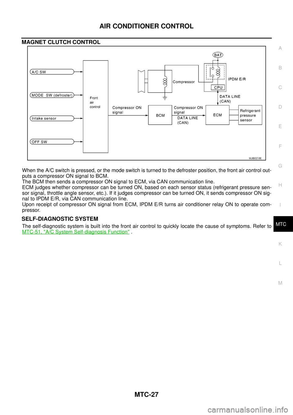
MAGNET CLUTCH CONTROL
When the A/C switch is pressed, or the mode switch is turned to the defroster position, the front air control out-
puts a compressor ON signal to BCM.
The BCM then sends a compressor ON signal to ECM, via CAN communication line.
ECM judges whether compressor can be turned ON, based on each sensor status (refrigerant pressure sen-
sor signal, throttle angle sensor, etc.). If it judges compressor can be turned ON, it sends compressor ON sig-
nal to IPDM E/R, via CAN communication line.
Upon receipt of compressor ON signal from ECM, IPDM E/R turns air conditioner relay ON to operate com-
pressor.
SELF-DIAGNOSTIC SYSTEM
The self-diagnostic system is built into the front air control to quickly locate the cause of symptoms. Refer to
MTC-51, "
A/C System Self-diagnosis Function".
MJIB0218E
Page 2437 of 3171

MTC-50
TROUBLE DIAGNOSIS
21 V Mode door motor feedback ON — 0 - 5V
22 SB Air mix door motor feedback ON — 0 - 5V
23 G Sensor power ON — 5V
25 LG Rear defroster status
26 P Sensor return ON — 0 - 5V
36 PPTC heater relay 1
(LHD models)ONRelay ON Battery voltage
Relay OFF 0V
37 LGPTC heater relay 2
(LHD models)ONRelay ON Battery voltage
Relay OFF 0V
38 BRPTC heater relay 3
(LHD models)ONRelay ON Battery voltage
Relay OFF 0V
39 YSeat heater
(LHD models)ONSeat heater ON Battery voltage
Seat heater OFF 0V
40 RMirror heater
(LHD models)ONMirror heater ON Battery voltage
Mirror heater OFF 0V
41 LCAN-H
(LHD models)ON — 0 - 5V
42 PCAN-L
(LHD models)ON — 0 - 5V Te r m i -
nal No.Wire
colorItemIgnition
switchConditionVoltage (V)
(Approx.)
Page 2459 of 3171
MTC-72
TROUBLE DIAGNOSIS
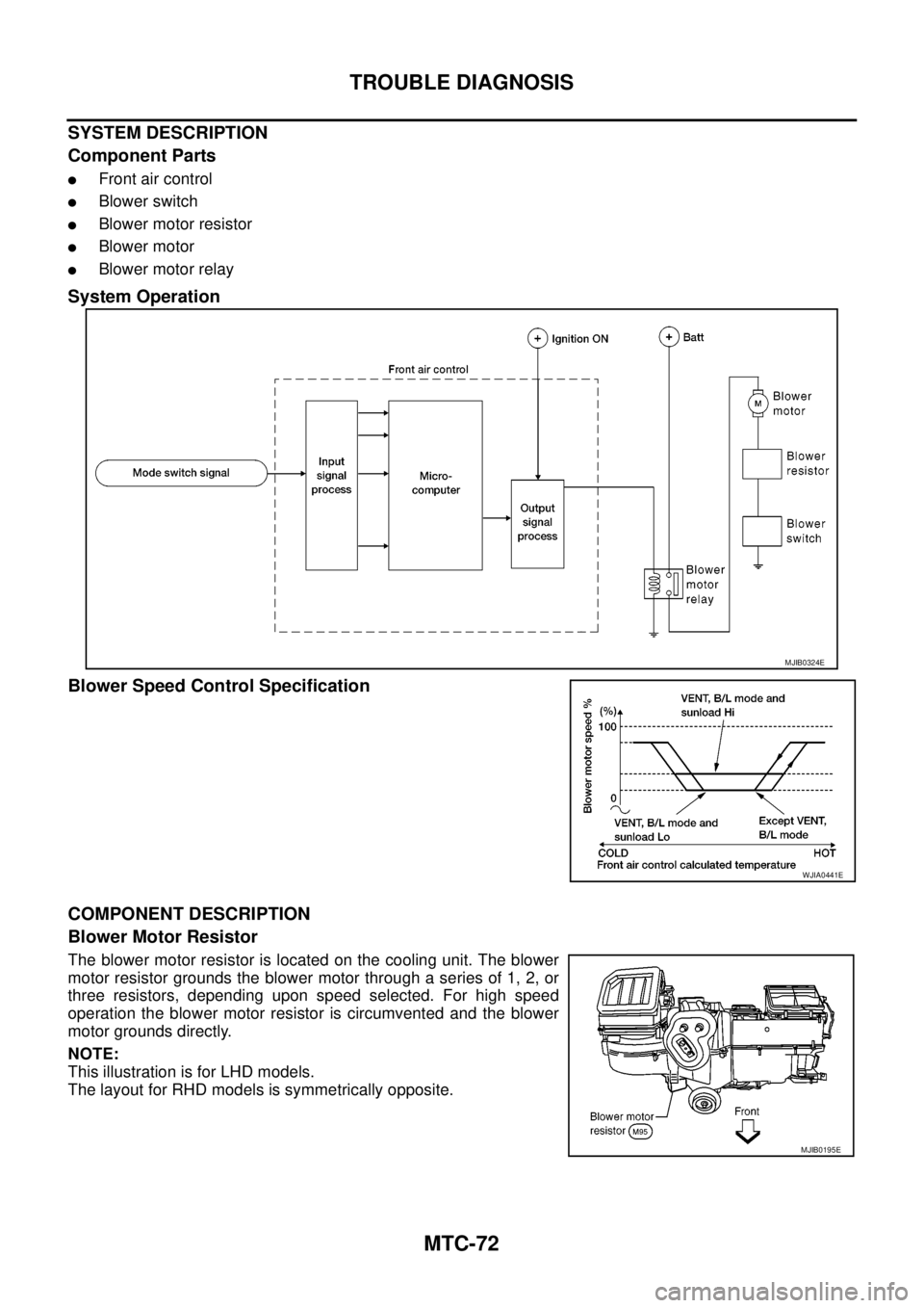
SYSTEM DESCRIPTION
Component Parts
lFront air control
lBlower switch
lBlower motor resistor
lBlower motor
lBlower motor relay
System Operation
Blower Speed Control Specification
COMPONENT DESCRIPTION
Blower Motor Resistor
The blower motor resistor is located on the cooling unit. The blower
motor resistor grounds the blower motor through a series of 1, 2, or
three resistors, depending upon speed selected. For high speed
operation the blower motor resistor is circumvented and the blower
motor grounds directly.
NOTE:
This illustration is for LHD models.
The layout for RHD models is symmetrically opposite.
MJIB0324E
WJIA0441E
MJIB0195E
Page 2461 of 3171
MTC-74
TROUBLE DIAGNOSIS
4.CHECK BLOWER MOTOR RELAY
Refer toMTC-77, "
Blower Motor Relay".
OK or NG
OK >> GO TO 5.
NG >> Replace blower motor relay.
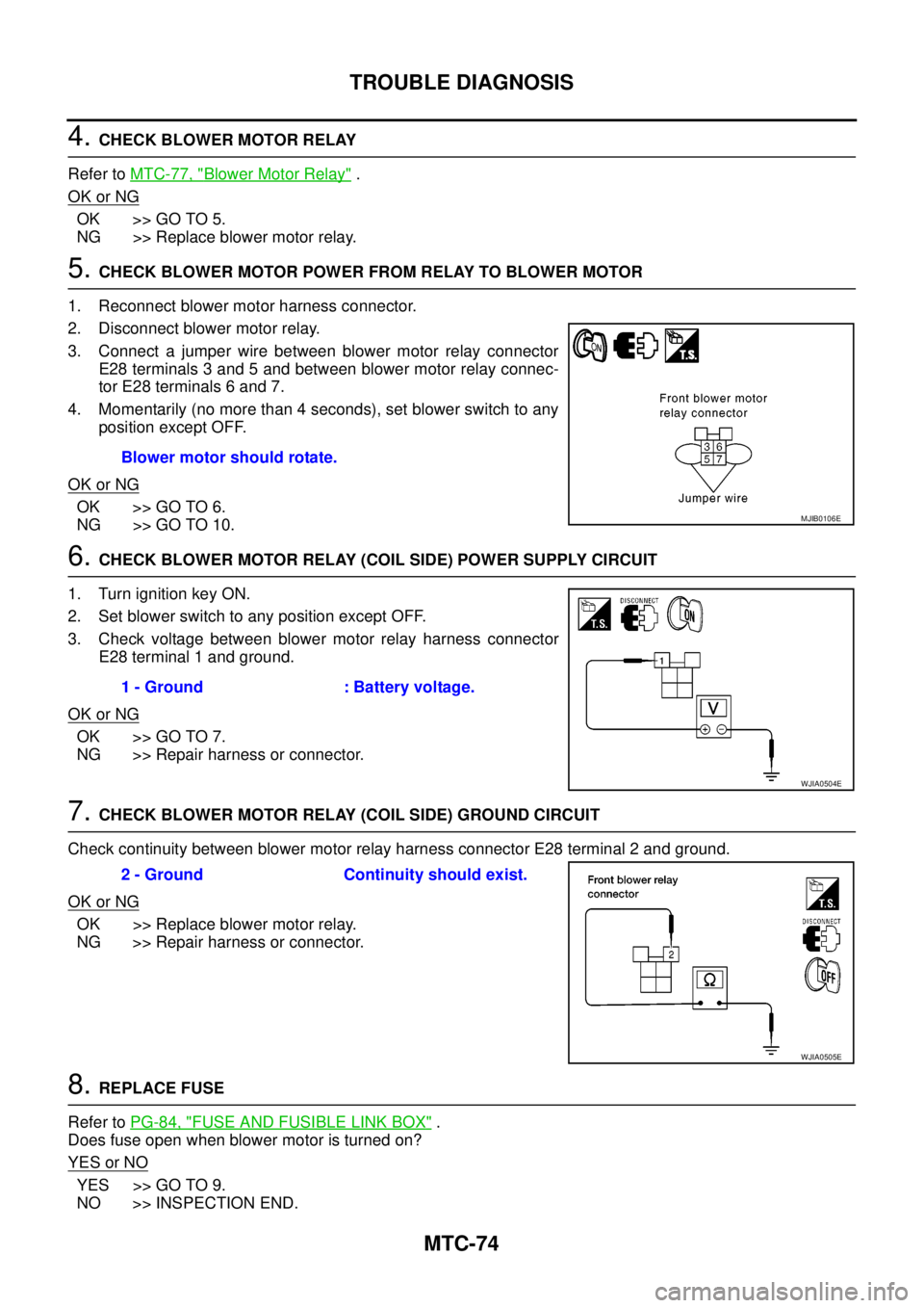
5.CHECK BLOWER MOTOR POWER FROM RELAY TO BLOWER MOTOR
1. Reconnect blower motor harness connector.
2. Disconnect blower motor relay.
3. Connect a jumper wire between blower motor relay connector
E28 terminals 3 and 5 and between blower motor relay connec-
tor E28 terminals 6 and 7.
4. Momentarily (no more than 4 seconds), set blower switch to any
position except OFF.
OK or NG
OK >> GO TO 6.
NG >> GO TO 10.
6.CHECK BLOWER MOTOR RELAY (COIL SIDE) POWER SUPPLY CIRCUIT
1. Turn ignition key ON.
2. Set blower switch to any position except OFF.
3. Check voltage between blower motor relay harness connector
E28 terminal 1 and ground.
OK or NG
OK >> GO TO 7.
NG >> Repair harness or connector.
7.CHECK BLOWER MOTOR RELAY (COIL SIDE) GROUND CIRCUIT
Check continuity between blower motor relay harness connector E28 terminal 2 and ground.
OK or NG
OK >> Replace blower motor relay.
NG >> Repair harness or connector.
8.REPLACE FUSE
Refer toPG-84, "
FUSE AND FUSIBLE LINK BOX".
Does fuse open when blower motor is turned on?
YESorNO
YES >> GO TO 9.
NO >> INSPECTION END.Blower motor should rotate.
MJIB0106E
1 - Ground : Battery voltage.
WJIA0504E
2 - Ground Continuity should exist.
WJIA0505E
Page 2462 of 3171
TROUBLE DIAGNOSIS
MTC-75
C
D
E
F
G
H
I
K
L
MA
B
MTC
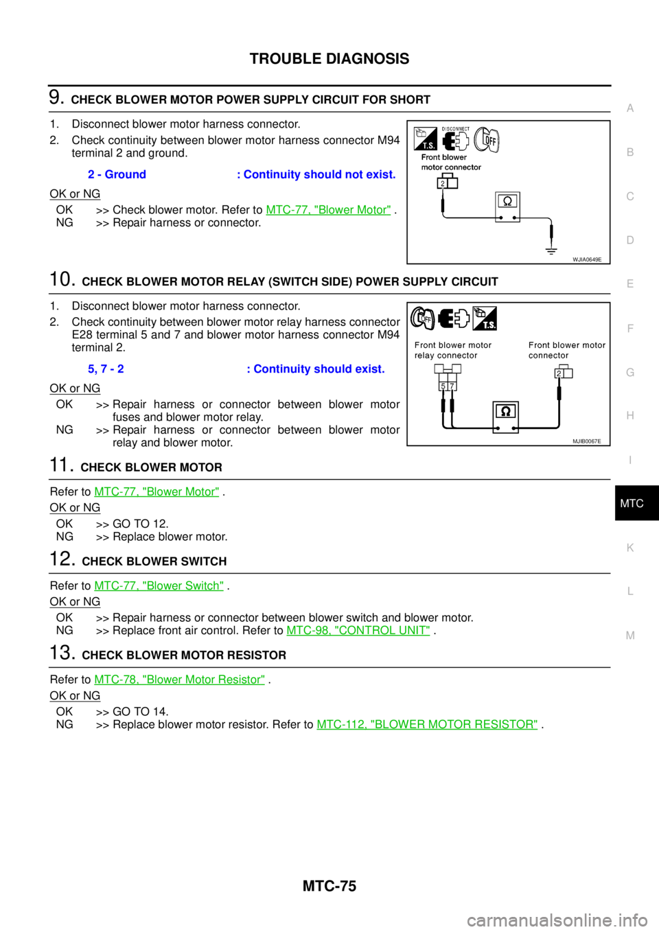
9.CHECK BLOWER MOTOR POWER SUPPLY CIRCUIT FOR SHORT
1. Disconnect blower motor harness connector.
2. Check continuity between blower motor harness connector M94
terminal 2 and ground.
OK or NG
OK >> Check blower motor. Refer toMTC-77, "Blower Motor".
NG >> Repair harness or connector.
10.CHECK BLOWER MOTOR RELAY (SWITCH SIDE) POWER SUPPLY CIRCUIT
1. Disconnect blower motor harness connector.
2. Check continuity between blower motor relay harness connector
E28 terminal 5 and 7 and blower motor harness connector M94
terminal 2.
OK or NG
OK >> Repair harness or connector between blower motor
fuses and blower motor relay.
NG >> Repair harness or connector between blower motor
relay and blower motor.
11 .CHECK BLOWER MOTOR
Refer toMTC-77, "
Blower Motor".
OK or NG
OK >> GO TO 12.
NG >> Replace blower motor.
12.CHECK BLOWER SWITCH
Refer toMTC-77, "
Blower Switch".
OK or NG
OK >> Repair harness or connector between blower switch and blower motor.
NG >> Replace front air control. Refer toMTC-98, "
CONTROL UNIT".
13.CHECK BLOWER MOTOR RESISTOR
Refer toMTC-78, "
Blower Motor Resistor".
OK or NG
OK >> GO TO 14.
NG >> Replace blower motor resistor. Refer toMTC-112, "
BLOWER MOTOR RESISTOR". 2 - Ground : Continuity should not exist.
WJIA0649E
5, 7 - 2 : Continuity should exist.
MJIB0067E
Page 2464 of 3171
TROUBLE DIAGNOSIS
MTC-77
C
D
E
F
G
H
I
K
L
MA
B
MTC
COMPONENT INSPECTION
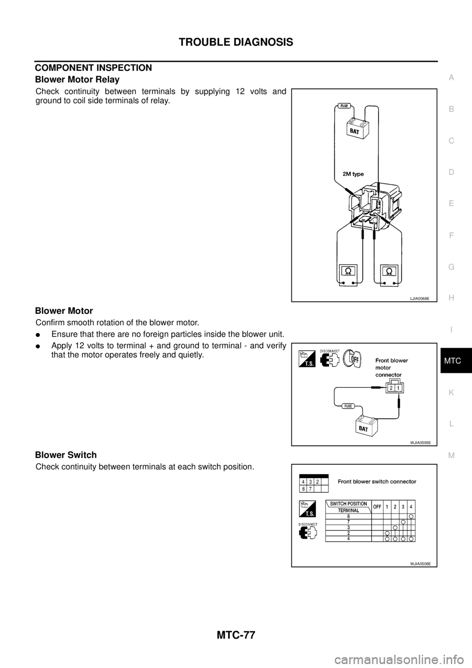
Blower Motor Relay
Check continuity between terminals by supplying 12 volts and
ground to coil side terminals of relay.
Blower Motor
Confirm smooth rotation of the blower motor.
lEnsure that there are no foreign particles inside the blower unit.
lApply 12 volts to terminal + and ground to terminal - and verify
that the motor operates freely and quietly.
Blower Switch
Check continuity between terminals at each switch position.
LJIA0068E
WJIA0595E
WJIA0508E
Page 2530 of 3171

PG-1
POWER SUPPLY, GROUND & CIRCUIT ELEMENTS
K ELECTRICAL
CONTENTS
C
D
E
F
G
H
I
J
L
M
SECTIONPG
A
B
PG
POWER SUPPLY, GROUND & CIRCUIT ELEMENTS
PRECAUTIONS .......................................................... 3
Precautions for Supplemental Restraint System
(SRS)“AIRBAG”and“SEATBELTPRE-TEN-
SIONER” .................................................................. 3
Wiring Diagrams and Trouble Diagnosis .................. 3
POWER SUPPLY ROUTING CIRCUIT ...................... 4
Schematic ................................................................ 4
Wiring Diagram — POWER — ................................. 5
BATTERY POWER SUPPLY — IGNITION SW.
IN ANY POSITION ................................................ 5
ACCESSORY POWER SUPPLY — IGNITION
SW. IN ACC OR ON ............................................ 10
IGNITION POWER SUPPLY — IGNITION SW.
IN ON ................................................................... 11
IGNITION POWER SUPPLY — IGNITION SW.
IN ON AND/OR START ....................................... 12
IPDM E/R (INTELLIGENT POWER DISTRIBUTION
MODULE ENGINE ROOM) ...................................... 14
System Description ................................................ 14
SYSTEMS CONTROLLED BY IPDM E/R ........... 14
CAN COMMUNICATION LINE CONTROL ......... 14
IPDM E/R STATUS CONTROL ........................... 15
CAN Communication System Description .............. 15
Function of Detecting Ignition Relay Malfunction ... 15
CONSULT-II Function (IPDM E/R) ......................... 16
CONSULT-II BASIC OPERATION ...................... 16
SELF-DIAGNOSTIC RESULTS .......................... 17
DATA MONITOR ................................................. 17
CAN DIAG SUPPORT MNTR ............................. 18
ACTIVE TEST ..................................................... 18
Auto Active Test ..................................................... 19
DESCRIPTION .................................................... 19
OPERATION PROCEDURE ............................... 19
INSPECTION IN AUTO ACTIVE TEST MODE... 20
Schematic .............................................................. 22
IPDM E/R Terminal Arrangement ........................... 23
Check IPDM E/R Power Supply and Ground Circuit... 24Inspection with CONSULT-II (Self-Diagnosis) ........ 25
Removal and Installation of IPDM E/R ................... 26
REMOVAL ........................................................... 26
INSTALLATION ................................................... 26
GROUND CIRCUIT ................................................... 27
Ground Distribution ................................................. 27
MAIN HARNESS ................................................. 27
ENGINE ROOM HARNESS ................................ 30
ENGINE CONTROL HARNESS .......................... 34
BODY HARNESS (LH SIDE) .............................. 35
BODY HARNESS (RH SIDE) .............................. 36
DEFOGGER CABLE ........................................... 37
HARNESS ................................................................. 38
Harness Layout ...................................................... 38
HOW TO READ HARNESS LAYOUT ................. 38
OUTLINE/DOUBLE CAB MODELS .................... 39
OUTLINE/KING CAB MODELS .......................... 40
MAIN HARNESS/LHD MODELS ......................... 41
MAIN HARNESS/RHD MODELS ........................ 44
ENGINE ROOM HARNESS/LHD MODELS ........ 47
ENGINE ROOM HARNESS/RHD MODELS ....... 49
ENGINE CONTROL HARNESS .......................... 51
CHASSIS HARNESS .......................................... 53
BODY HARNESS (LH SIDE)/DOUBLE CAB
MODELS ............................................................. 54
BODY HARNESS (RH SIDE)/DOUBLE CAB
MODELS ............................................................. 56
BODY HARNESS (LH SIDE)/KING CAB MOD-
ELS ...................................................................... 58
BODY HARNESS (RH SIDE)/KING CAB MOD-
ELS ...................................................................... 60
ROOM LAMP HARNESS .................................... 62
FRONT DOOR LH HARNESS/LHD MODELS .... 63
FRONT DOOR RH HARNESS/LHD MODELS ... 63
FRONT DOOR LH HARNESS/RHD MODELS ... 64
FRONT DOOR RH HARNESS/RHD MODELS ... 64
REAR DOOR LH HARNESS/DOUBLE CAB
MODELS ............................................................. 65
REAR DOOR RH HARNESS/DOUBLE CAB
MODELS ............................................................. 65
Page 2531 of 3171

PG-2
REAR DOOR LH HARNESS/KING CAB MOD-
ELS ...................................................................... 66
REAR DOOR RH HARNESS/KING CAB MOD-
ELS ...................................................................... 66
TAIL HARNESS ................................................... 67
Wiring Diagram Codes (Cell Codes) ....................... 68
ELECTRICAL UNITS LOCATION ............................. 71
Electrical Units Location ......................................... 71
ENGINE COMPARTMENT .................................. 71
PASSENGER COMPARTMENT .......................... 72
Fuse ........................................................................ 74
Fusible Link ............................................................ 74
Circuit Breaker (Built Into BCM) ............................. 74
HARNESS CONNECTOR ......................................... 75
Description .............................................................. 75
HARNESS CONNECTOR (TAB-LOCKING
TYPE) .................................................................. 75
HARNESS CONNECTOR (SLIDE-LOCKINGTYPE) .................................................................. 76
HARNESS CONNECTOR (DIRECT-CONNECT
SRS COMPONENT TYPE) .................................. 77
ELECTRICAL UNITS ................................................ 78
Terminal Arrangement ............................................. 78
STANDARDIZED RELAY .......................................... 79
Description .............................................................. 79
NORMAL OPEN, NORMAL CLOSED AND
MIXED TYPE RELAYS ........................................ 79
TYPE OF STANDARDIZED RELAYS .................. 79
SUPER MULTIPLE JUNCTION (SMJ) ...................... 81
Terminal Arrangement ............................................. 81
FUSE BLOCK - JUNCTION BOX (J/B) .................... 83
Terminal Arrangement ............................................. 83
FUSE AND FUSIBLE LINK BOX .............................. 84
Terminal Arrangement ............................................. 84
FUSE AND RELAY BOX ........................................... 85
Terminal Arrangement ............................................. 85