Page 1000 of 3171

EC-20
ENGINE CONTROL SYSTEM
MAXIMUM AMOUNT CONTROL
Input/Output Signal Chart
The maximum injection amount is controlled to an optimum by the engine speed, intake air amount, engine
coolant temperature, and accelerator opening in accordance with the driving conditions.
This prevents the oversupply of the injection amount caused by decreased air density at a high altitude or dur-
ing a system failure.
DECELERATION CONTROL
Input/Output Signal Chart
The ECM sends a fuel cut signal to the fuel injectors and fuel pump during deceleration for better fuel effi-
ciency. The ECM determines the time of deceleration according to signals from the accelerator pedal position
sensor and crankshaft position sensor.
Fuel Injection Timing Control SystemEBS01KCF
DESCRIPTION
The target fuel injection timing in accordance with the engine speed and the fuel injection amount are recorded
as a map in the ECM beforehand. The ECM determines the optimum injection timing using sensor signals
accordance with the map.
Air Conditioning Cut ControlEBS01KCG
INPUT / OUTPUT SIGNAL CHART
*1: The input signal is sent to the ECM through CAN communication line.
*2: The output signal is sent from the ECM through CAN communication line.
SYSTEM DESCRIPTION
This system improves acceleration when the air conditioner is used.
When the accelerator pedal is fully depressed, the air conditioner is turned off for a few seconds.
When engine coolant temperature becomes excessively high, the air conditioner is turned off. This continues
until the engine coolant temperature returns to normal.
Fuel Cut Control (At No Load & High Engine Speed)EBS01KCH
INPUT/OUTPUT SIGNAL CHART
*: The input signal is sent to the ECM through CAN communication line.Sensor Input Signal to ECM ECM Function Actuator
Mass air flow sensor Amount of intake air
Fuel injection
control (maxi-
mum amount
control)Fuel injector Engine coolant temperature sensor Engine coolant temperature
Crankshaft position sensor Engine speed
Accelerator pedal position sensor Accelerator pedal position
Sensor Input Signal to ECM ECM Function Actuator
Accelerator pedal position sensor Accelerator pedal position Fuel injection
control (decel-
eration control)Fuel injector
Fuel pump
Crankshaft position sensor Engine speed
Sensor Input Signal to ECM ECM Function Actuator
Air conditioner switch
Air conditioner ON signal*
1
Air conditioner
cut controlAir conditioner relay*2
Accelerator pedal position sensor Accelerator pedal opening angle
Wheel sensor
Vehicle speed*
1
Engine coolant temperature sensor Engine coolant temperature
Refrigerant pressure sensor Refrigerant pressure
Sensor Input Signal to ECM ECM Function Actuator
Wheel sensor Vehicle speed*
Fuel cut control Fuel injector Accelerator pedal position sensor Accelerator pedal position
Crankshaft position sensor Engine speed
Page 1017 of 3171

TROUBLE DIAGNOSIS
EC-37
C
D
E
F
G
H
I
J
K
L
MA
EC
DTC Inspection Priority ChartEBS01KCU
If some DTCs are displayed at the same time, perform inspections one by one based on the following priority
chart.
NOTE:
If DTC U1000 is displayed with other DTC, first perform the trouble diagnosis for DTC U1000. Refer to
EC-79, "
DTC U1000 CAN COMMUNICATION LINE".
Priority Detected items (DTC)
1
lU1000 CAN communication line
lP0016 Crankshaft position - camshaft position correlation
lP0102 P0103 Mass air flow sensor
lP0112 P0113 Intake air temperature sensor
lP0117 P0118 Engine coolant temperature sensor
lP0122 P0123 P0222 P0223 P2135 Accelerator pedal position sensor
lP0182 P0183 Fuel pump temperature sensor
lP0192 P0193 Fuel rail pressure sensor
lP0237 P0238 Turbocharger boost sensor
lP0335 P0336 Crankshaft position sensor
lP0340 P0341 Camshaft position sensor
lP0563 Battery voltage
lP0605 P0606 P1616 ECM
lP0642 P0643 P0652 P0653 Sensor power supply
lP1610 - P1615 NATS
lP1622 P1623 Injector adjustment value
lP2228 P2229 Barometric pressure sensor
2
lP0089 P0628 P0629 P1272 - P1275 Fuel pump
lP0200 - P0204 P1268 - P1271 P2146 - P2149 Fuel injector
lP0686 ECM relay
3
lP0088 P0093 Fuel system
lP0217 Engine over temperature (OVERHEAT)
lP0234 Turbocharger system
lP0501 P0502 P0503 ASCD vehicle speed sensor
lP0504 ASCD brake switch
lP0580 P0581 ASCD steering switch
Page 1023 of 3171

TROUBLE DIAGNOSIS
EC-43
C
D
E
F
G
H
I
J
K
L
MA
EC
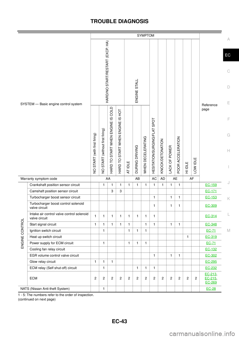
1 - 5: The numbers refer to the order of inspection.
(continued on next page)
ENGINE CONTROL
Crankshaftpositionsensorcircuit 1111111111EC-159
Camshaft position sensor circuit 3 3EC-171
Turbocharger boost sensor circuit 1 1 1EC-153
Turbocharger boost control solenoid
valve circuit111EC-309
Intake air control valve control solenoid
valve circuit11111111EC-314
Start signal circuit 1 1 1 1 1 1 1 1 1EC-348
Ignition switch circuit 1 1 1 1EC-71
Heat up switch circuit1EC-319
Power supply for ECM circuit 1 1 1 1EC-71
Cooling fan relay circuitEC-132
EGR volume control valve circuit 1 1 1EC-302
Glow relay circuit 1 1 1EC-295
ECM relay (Self shut-off) circuit 1 1 1 1EC-232
ECM 2222222222222EC-213
,
EC-215
,
EC-269
NATS (Nissan Anti-theft System) 1EC-28
SYSTEM — Basic engine control systemSYMPTOM
Reference
pageHARD/NO START/RESTART (EXCP. HA)
ENGINE STALL
HESITATION/SURGING/FLAT SPOT
KNOCK/DETONATION
LACK OF POWER
POOR ACCELERATION
HI IDLE
LOW IDLE NO START (with first firing)
NO START (without first firing)
HARD TO START WHEN ENGINE IS COLD
HARD TO START WHEN ENGINE IS HOT
AT I D L E
DURING DRIVING
WHEN DECELERATING
Warranty symptom code AA AB AC AD AE AF
Page 1025 of 3171

TROUBLE DIAGNOSIS
EC-45
C
D
E
F
G
H
I
J
K
L
MA
EC
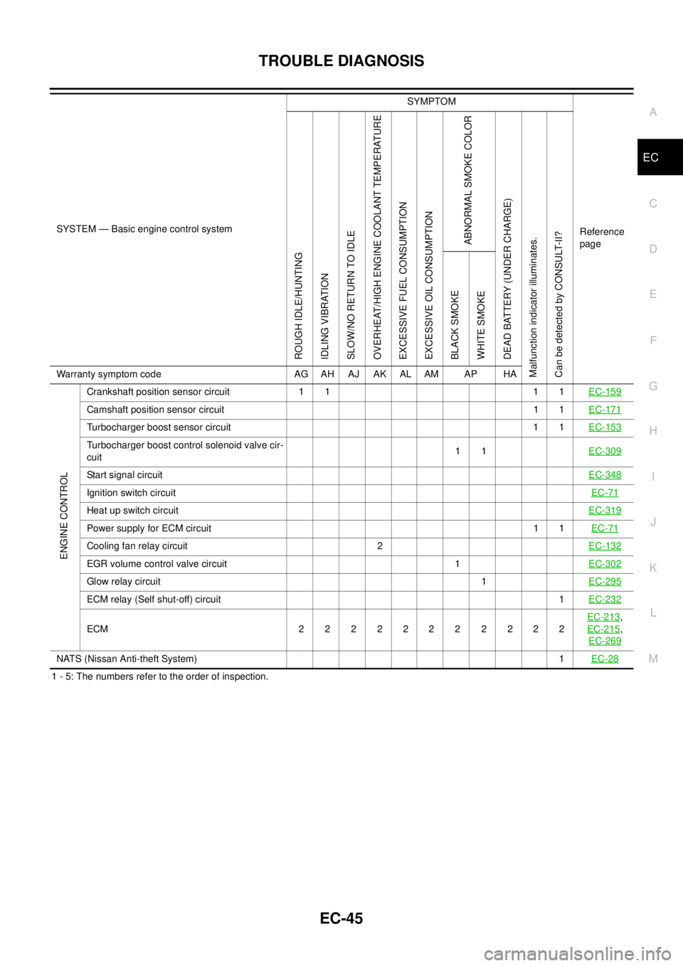
1 - 5: The numbers refer to the order of inspection.
ENGINE CONTROL
Crankshaft position sensor circuit 1 1 1 1EC-159
Camshaft position sensor circuit11EC-171
Turbocharger boost sensor circuit 1 1EC-153
Turbocharger boost control solenoid valve cir-
cuit11EC-309
Start signal circuitEC-348
Ignition switch circuitEC-71
Heat up switch circuitEC-319
Power supply for ECM circuit11EC-71
Cooling fan relay circuit 2EC-132
EGR volume control valve circuit 1EC-302
Glow relay circuit1EC-295
ECM relay (Self shut-off) circuit1EC-232
ECM 22 22222 2222EC-213
,
EC-215
,
EC-269
NATS (Nissan Anti-theft System)1EC-28
SYSTEM — Basic engine control systemSYMPTOM
Reference
page
ROUGH IDLE/HUNTING
IDLING VIBRATION
SLOW/NO RETURN TO IDLE
OVERHEAT/HIGH ENGINE COOLANT TEMPERATURE
EXCESSIVE FUEL CONSUMPTION
EXCESSIVE OIL CONSUMPTION
ABNORMAL SMOKE COLOR
DEAD BATTERY (UNDER CHARGE)
Malfunction indicator illuminates.
Can be detected by CONSULT-II?BLACK SMOKE
WHITE SMOKE
Warranty symptom code AG AH AJ AK AL AM AP HA
Page 1026 of 3171
EC-46
TROUBLE DIAGNOSIS
Engine Control Component Parts Location
EBS01KCX
1. IPDM E/R 2. ECM 3. Glow relay
4. Turbocharger boost sensor 5. Refrigerant pressure sensor 6. Engine coolant temperature sensor
7. Fuel pump 8. Cooling fan motor 9. Intake air control valve actuator
10. Turbocharger boost control solenoid
valve11. Mass air flow sensor 12. Turbocharger boost control actuator
13. Camshaft position sensor 14. Glow plug 15. Fuel injector
16. Fuel rail pressure sensor 17. Intake air control valve control
solenoid valve18. EGR volume control valve
MBIB1198E
Page 1028 of 3171
EC-48
TROUBLE DIAGNOSIS
: Vehicle front
1. Glow relay 2. ECM 3. Crankshaft position sensor
(View from under the vehicle)
4. Turbocharger boost sensor
(View with front grille removed)5. ASCD brake switch 6. Stop lamp switch
7. Accelerator pedal position sensor
MBIB1249E
Page 1034 of 3171
![NISSAN NAVARA 2005 Repair Workshop Manual EC-54
TROUBLE DIAGNOSIS
15 GRIntake air control valve con-
trol solenoid valve[Engine is running]BATTERY VOLTAGE
(11 - 14V)
[Ignition switch OFF]
lFor a few seconds after turning ignition
switch OFFAp NISSAN NAVARA 2005 Repair Workshop Manual EC-54
TROUBLE DIAGNOSIS
15 GRIntake air control valve con-
trol solenoid valve[Engine is running]BATTERY VOLTAGE
(11 - 14V)
[Ignition switch OFF]
lFor a few seconds after turning ignition
switch OFFAp](/manual-img/5/57362/w960_57362-1033.png)
EC-54
TROUBLE DIAGNOSIS
15 GRIntake air control valve con-
trol solenoid valve[Engine is running]BATTERY VOLTAGE
(11 - 14V)
[Ignition switch OFF]
lFor a few seconds after turning ignition
switch OFFApproximately 0.3V
21
22
23
24G
P
W
WFuel injector No. 2
Fuel injector No. 2
Fuel injector No. 3
Fuel injector No. 3[Engine is running]
lWarm-up condition
lIdle speed
NOTE:
The pulse cycle changes depending on rpm
at idleApproximately 7.5V
[Engine is running]
lWarm-up condition
lEngine speed: 2,000 rpmApproximately 8.0V
25
26
27
28Y
O
GR
VEGR volume control valve[Engine is running]
lWarm-up condition
lIdle speed0.1 - 14V
(Voltage signals of each ECM
terminals differ according to the
control position of EGR volume
control valve.)
29 B Fuel pump[Engine is running]
lWarm-up condition
lIdle speed0.5 - 1.0V
[Engine is running]
lWarm-up condition
lEngine speed: 2,000 rpm0.5 - 1.0V
37 G Glow relay Refer toEC-295, "
GLOW CONTROL SYSTEM". TERMI-
NAL
NO.WIRE
COLORITEM CONDITIONDATA
(DC Voltage and Pulse Signal)
MBIB1297E
MBIB1298E
MBIB0887E
MBIB0888E
Page 1038 of 3171
![NISSAN NAVARA 2005 Repair Workshop Manual EC-58
TROUBLE DIAGNOSIS
: Average voltage for pulse signal (Actual pulse signal can be confirmed by oscilloscope.)101 W ASCD brake switch[Ignition switch ON]
lBrake pedal: Fully released (A/T)
lClutch NISSAN NAVARA 2005 Repair Workshop Manual EC-58
TROUBLE DIAGNOSIS
: Average voltage for pulse signal (Actual pulse signal can be confirmed by oscilloscope.)101 W ASCD brake switch[Ignition switch ON]
lBrake pedal: Fully released (A/T)
lClutch](/manual-img/5/57362/w960_57362-1037.png)
EC-58
TROUBLE DIAGNOSIS
: Average voltage for pulse signal (Actual pulse signal can be confirmed by oscilloscope.)101 W ASCD brake switch[Ignition switch ON]
lBrake pedal: Fully released (A/T)
lClutch pedal and brake pedal:
Fully released (M/T)BATTERY VOLTAGE
(11 - 14V)
[Ignition switch ON]
lBrake pedal: Slightly depressed (A/T)
lClutch pedal and/or brake pedal:
Slightly depressed (M/T)Approximately 0V
102 SB ASCD steering switch[Ignition switch ON]
lASCD steering switch: OFFApproximately 4.3V
[Ignition switch ON]
lON/OFF switch: PressedApproximately 0.3V
[Ignition switch ON]
lCANCEL switch: PressedApproximately 1.3V
[Ignition switch ON]
lRESUME/ACCELERATE switch: PressedApproximately 3.3V
[Ignition switch ON]
lSET/COAST switch: PressedApproximately 2.3V
103 BASCD steering switch
ground[Ignition switch ON]Approximately 0.3V
105 BR ECM relay (self shut-off)[Ignition switch ON]
[Ignition switch OFF]
lFor a few seconds after turning ignition
switch OFFApproximately 1.0V
[Ignition switch OFF]
lMore than a few seconds after turning igni-
tion switch OFFBATTERY VOLTAGE
(11 - 14V)
107
108R
RIgnition switch[Ignition switch ON]BATTERY VOLTAGE
(11 - 14V)
11 0G(A/T)
O (M/T)Park/Neutral position switch[Ignition switch ON]
lShift lever: P or N (A/T), Neutral (M/T)Approximately 0V
[Ignition switch ON]
lExcept the above positionBATTERY VOLTAGE
(11 - 14V)
113 BR ECM relay (self shut-off)[Ignition switch ON]
[Ignition switch OFF]
lFor a few seconds after turning ignition
switch OFFApproximately 1.0V
[Ignition switch OFF]
lMore than a few seconds after turning igni-
tion switch OFFBATTERY VOLTAGE
(11 - 14V)
114 B ECM ground[Engine is running]
lIdle speedApproximately 0V
11 9
120R
GPower supply for ECM[Ignition switch ON]BATTERY VOLTAGE
(11 - 14V)
121 VPower supply for ECM
(Back-up)[Ignition switch OFF]BATTERY VOLTAGE
(11 - 14V) TERMI-
NAL
NO.WIRE
COLORITEM CONDITIONDATA
(DC Voltage and Pulse Signal)