2005 NISSAN NAVARA relay
[x] Cancel search: relayPage 417 of 3171
![NISSAN NAVARA 2005 Repair Workshop Manual TROUBLE DIAGNOSIS
ATC-83
C
D
E
F
G
H
I
K
L
MA
B
AT C
1.CHECK FUSES
Check 15A fuses [No. 24 and 27, (located in the fuse and fusible link box)]. For fuse layout, refer toPG-84,
"FUSE AND FUSIBLE LINK B NISSAN NAVARA 2005 Repair Workshop Manual TROUBLE DIAGNOSIS
ATC-83
C
D
E
F
G
H
I
K
L
MA
B
AT C
1.CHECK FUSES
Check 15A fuses [No. 24 and 27, (located in the fuse and fusible link box)]. For fuse layout, refer toPG-84,
"FUSE AND FUSIBLE LINK B](/manual-img/5/57362/w960_57362-416.png)
TROUBLE DIAGNOSIS
ATC-83
C
D
E
F
G
H
I
K
L
MA
B
AT C
1.CHECK FUSES
Check 15A fuses [No. 24 and 27, (located in the fuse and fusible link box)]. For fuse layout, refer toPG-84,
"FUSE AND FUSIBLE LINK BOX".
OK or NG
OK >> GO TO 2.
NG >> GO TO 10.
2.CHECK BLOWER MOTOR POWER SUPPLY CIRCUIT
1. Turn ignition switch OFF.
2. Disconnect blower motor connector.
3. Turn ignition switch ON.
4. Turn the blower control dial to select any mode except off.
5. Check voltage between blower motor harness connector M94
terminal 2 and ground.
OK or NG
OK >> GO TO 12.
NG >> GO TO 3.
3.CHECK BLOWER MOTOR RELAY (SWITCH SIDE) POWER SUPPLY CIRCUIT
1. Turn ignition switch OFF.
2. Disconnect blower motor relay.
3. Check voltage between blower motor relay harness connector
E28 terminals 3 and 6 and ground.
OK or NG
OK >> GO TO 4.
NG >> Repair harness or connector.
4.CHECK BLOWER MOTOR RELAY
Refer toAT C - 8 6 , "
Blower Motor Relay".
OK or NG
OK >> GO TO 5.
NG >> Replace blower motor relay.
5.CHECK BLOWER MOTOR RELAY (SWITCH SIDE) CIRCUIT FOR OPEN
1. Turn ignition switch OFF.
2. Disconnect blower motor relay connector and blower motor con-
nector.
3. Check continuity between blower motor relay harness connector
E28 terminals 5 and 7 and blower motor harness connector M94
terminal 2.
OK or NG
OK >> GO TO 6.
NG >> Repair harness or connector.Fuses are good.
2 - Ground : Battery voltage.
MJIB0065E
3, 6 - Ground : Battery voltage.
MJIB0066E
5, 7 - 2 : Continuity should exist.
MJIB0067E
Page 418 of 3171
ATC-84
TROUBLE DIAGNOSIS
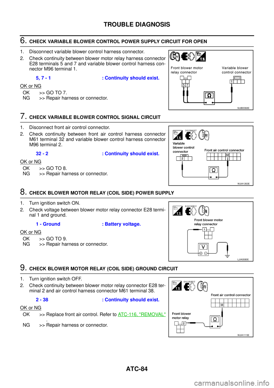
6.CHECK VARIABLE BLOWER CONTROL POWER SUPPLY CIRCUIT FOR OPEN
1. Disconnect variable blower control harness connector.
2. Check continuity between blower motor relay harness connector
E28 terminals 5 and 7 and variable blower control harness con-
nector M96 terminal 1.
OK or NG
OK >> GO TO 7.
NG >> Repair harness or connector.
7.CHECK VARIABLE BLOWER CONTROL SIGNAL CIRCUIT
1. Disconnect front air control connector.
2. Check continuity between front air control harness connector
M61 terminal 32 and variable blower control harness connector
M96 terminal 2.
OK or NG
OK >> GO TO 8.
NG >> Repair harness or connector.
8.CHECK BLOWER MOTOR RELAY (COIL SIDE) POWER SUPPLY
1. Turn ignition switch ON.
2. Check voltage between blower motor relay connector E28 termi-
nal 1 and ground.
OK or NG
OK >> GO TO 9.
NG >> Repair harness or connector.
9.CHECK BLOWER MOTOR RELAY (COIL SIDE) GROUND CIRCUIT
1. Turn ignition switch OFF.
2. Check continuity between blower motor relay connector E28 ter-
minal 2 and air control harness connector M61 terminal 38.
OK or NG
OK >> Replace front air control. Refer toAT C - 11 6 , "REMOVAL"
.
NG >> Repair harness or connector.5, 7 - 1 : Continuity should exist.
MJIB0068E
32 - 2 : Continuity should exist.
WJIA1263E
1 - Ground : Battery voltage.
LJIA0080E
2 - 38 : Continuity should exist.
WJIA1115E
Page 420 of 3171
ATC-86
TROUBLE DIAGNOSIS
COMPONENT INSPECTION
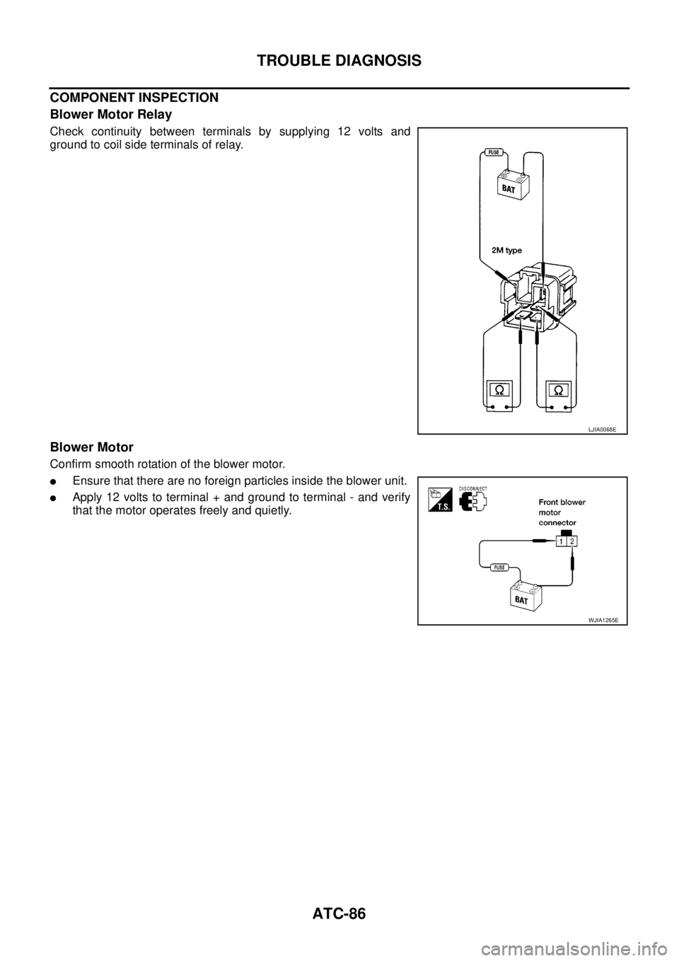
Blower Motor Relay
Check continuity between terminals by supplying 12 volts and
ground to coil side terminals of relay.
Blower Motor
Confirm smooth rotation of the blower motor.
lEnsure that there are no foreign particles inside the blower unit.
lApply 12 volts to terminal + and ground to terminal - and verify
that the motor operates freely and quietly.
LJIA0068E
WJIA1265E
Page 725 of 3171

THEFT WARNING SYSTEM
BL-141
C
D
E
F
G
H
J
K
L
MA
B
BL
2. A door is unlocked without using the keyfob.
3. Disconnect and connecting the battery connector before canceling armed phase.
POWER SUPPLY AND GROUND CIRCUIT
Power is supplied at all times
lthrough 10A fuse [No.19, located in the fuse block (J/B)]
lto combination meter (security indicator lamp) terminal 3
lthrough 50A fusible link (letterG, located in the fuse and fusible link box)
lto BCM terminal 57
lthrough 10A fuse [No. 21, located in the fuse block (J/B)]
lto BCM terminal 41
lthrough 15A fuse (No. 30, located in the fuse and fusible link box)
lto horn relay terminal 2
lthrough 20A fuse (No. 52, located in the IPDM E/R)
lthrough 20A fuse (No. 53, located in the IPDM E/R),
lto IPDM E/R internal CPU.
With the ignition switch in the ACC or ON position, power is supplied
lthrough 10A fuse [No. 4, located in the fuse block (J/B)]
lto BCM terminal 4.
Ground is supplied
lto BCM terminal 55
lthrough body grounds M21, M80 and M83
lto IPDM E/R terminals 38 and 59
lthrough body ground E21, E41 and E61.
INITIAL CONDITION TO ACTIVATE THE SYSTEM
The operation of the theft warning system is controlled by the engine hood and doors.
To activate the theft warning system, BCM must receive signals indicating the doors are closed and locked.
When a door is open, BCM terminal 12, 14, 15 or 16 receives a ground signal from each door switch.
When the engine hood is open, IPDM E/R terminal 41 receives a ground signal
THEFT WARNING SYSTEM ALARM OPERATION
The vehicle security system is triggered by
lopening a door
lopening the hood
ldetecting battery disconnect/connection.
The vehicle security system will be triggered once the system is in armed phase,
when BCM receives a ground signal at terminals 12, 14, 15, 16 (door switch) or IPDM E/R receives a ground
signal at terminal 41 (hood switch).
When the vehicle security system is triggered, siren control unit or horn is activate.
The alarm automatically turns off after 30 seconds, but will reactivate if the vehicle is tampered with again.
THEFT WARNING SYSTEM DEACTIVATION
To deactivate the theft warning system, a door must be unlocked with keyfob.
When the BCM receives either one of these signals or unlock signal from keyfob the theft warning system is
deactivated. (Disarmed phase)
CAN Communication System DescriptionEIS00DBY
Refer toLAN-23, "CAN COMMUNICATION".
Page 740 of 3171
BL-156
THEFT WARNING SYSTEM
TerminalsandReferenceValueforIPDME/R
EIS00DC3
*: When horn reminder is ON.
CONSULT-II Function (BCM)EIS00DC4
CONSULT-II can display each diagnostic item using the diagnostic test modes shown following.
CONSULT-II INSPECTION PROCEDURE
CAUTION:
If CONSULT-II is used with no connection of CONSULT-II CONVERTER, malfunctions might be
detected in self-diagnosis depending on control unit which carry out CAN communication.
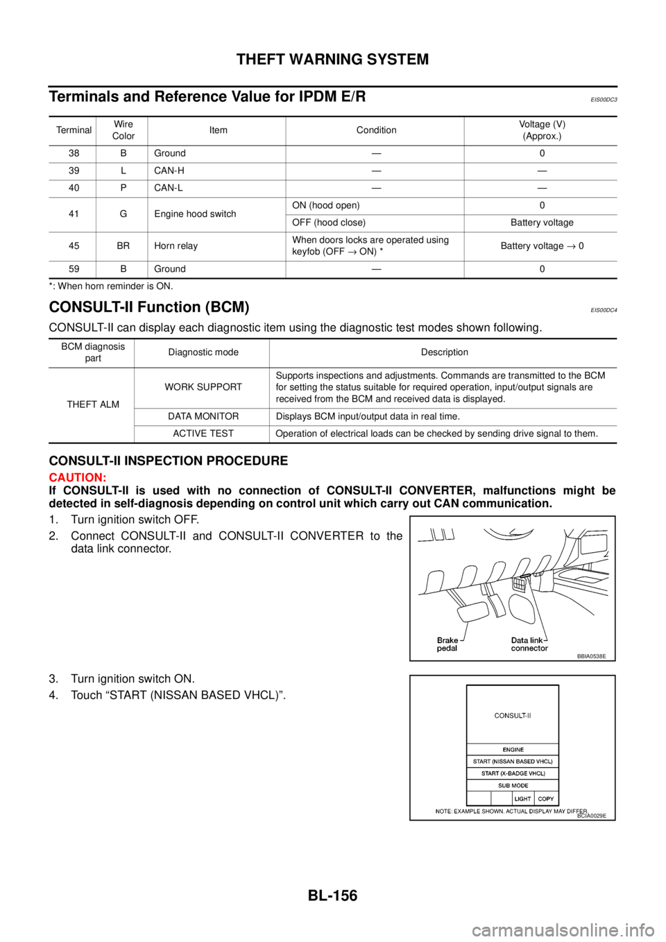
1. Turn ignition switch OFF.
2. Connect CONSULT-II and CONSULT-II CONVERTER to the
data link connector.
3. Turn ignition switch ON.
4. Touch “START (NISSAN BASED VHCL)”.
TerminalWire
ColorItem ConditionVoltage (V)
(Approx.)
38 B Ground — 0
39 L CAN-H — —
40 P CAN-L — —
41 G Engine hood switchON (hood open) 0
OFF (hood close) Battery voltage
45 BR Horn relayWhen doors locks are operated using
keyfob (OFF®ON) *Battery voltage®0
59 B Ground — 0
BCM diagnosis
partDiagnostic mode Description
THEFT ALMWORK SUPPORTSupports inspections and adjustments. Commands are transmitted to the BCM
for setting the status suitable for required operation, input/output signals are
received from the BCM and received data is displayed.
DATA MONITOR Displays BCM input/output data in real time.
ACTIVE TEST Operation of electrical loads can be checked by sending drive signal to them.
BBIA0538E
BCIA0029E
Page 753 of 3171
THEFT WARNING SYSTEM
BL-169
C
D
E
F
G
H
J
K
L
MA
B
BL
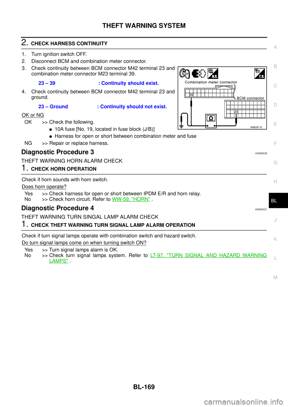
2.CHECK HARNESS CONTINUITY
1. Turn ignition switch OFF.
2. Disconnect BCM and combination meter connector.
3. Check continuity between BCM connector M42 terminal 23 and
combination meter connector M23 terminal 39.
4. Check continuity between BCM connector M42 terminal 23 and
ground.
OK or NG
OK >> Check the following.
l10Afuse[No.19,locatedinfuseblock(J/B)]
lHarness for open or short between combination meter and fuse
NG >> Repair or replace harness.
Diagnostic Procedure 3EIS00DCB
THEFT WARNING HORN ALARM CHECK
1.CHECK HORN OPERATION
Check if horn sounds with horn switch.
Does horn operate?
Yes >> Check harness for open or short between IPDM E/R and horn relay.
No >> Check horn circuit. Refer toWW-59, "
HORN".
Diagnostic Procedure 4EIS00DCC
THEFT WARNING TURN SINGAL LAMP ALARM CHECK
1.CHECK THEFT WARNING TURN SIGNAL LAMP ALARM OPERATION
Check if turn signal lamps operate with combination switch and hazard switch.
DoturnsignallampscomeonwhenturningswitchON?
Yes >> Turn signal lamps alarm is OK.
No >> Check turn signal lamps system. Refer toLT- 9 7 , "
TURN SIGNAL AND HAZARD WARNING
LAMPS". 23 – 39 : Continuity should exist.
23 – Ground : Continuity should not exist.
MIIB0871E
Page 823 of 3171
BRC-1
BRAKE CONTROL SYSTEM
F BRAKES
CONTENTS
C
D
E
G
H
I
J
K
L
M
SECTIONBRC
A
B
BRC
BRAKE CONTROL SYSTEM
ABS
PRECAUTIONS .......................................................... 3
Precautions for Supplemental Restraint System
(SRS)“AIRBAG”and“SEATBELTPRE-TEN-
SIONER” .................................................................. 3
Precautions for Brake System .................................. 3
Precautions for Brake Control .................................. 3
PREPARATION ........................................................... 4
Special Service Tools (SST) ..................................... 4
SYSTEM DESCRIPTION ............................................ 5
System Diagram ....................................................... 5
Functions .................................................................. 5
Operation That Is Not “System Error” ...................... 5
Fail-Safe Function .................................................... 5
ABS, EBD SYSTEM .............................................. 5
Hydraulic Circuit Diagram ........................................ 6
CAN COMMUNICATION ............................................ 7
System Description .................................................. 7
TROUBLE DIAGNOSIS .............................................. 8
How to Perform Trouble Diagnosis for Quick and
Accurate Repair ....................................................... 8
INTRODUCTION ................................................... 8
DIAGNOSIS FLOWCHART .................................. 9
ASKING COMPLAINTS ...................................... 10
EXAMPLE OF DIAGNOSIS SHEET ................... 10
Component Parts Location ...................................... 11
Schematic — ABS — ............................................. 12
Wiring Diagram — ABS — ..................................... 13
CONSULT- II Functions .......................................... 17
CONSULT-II MAIN FUNCTION ........................... 17
CONSULT-II BASIC OPERATION PROCEDURE
... 17
Self-Diagnosis ........................................................ 18
OPERATION PROCEDURE ............................... 18
ERASE MEMORY ............................................... 18
DISPLAY ITEM LIST ........................................... 18
Data Monitor ........................................................... 20
OPERATION PROCEDURE ............................... 20
DISPLAY ITEM LIST ........................................... 20Active Test .............................................................. 21
OPERATION PROCEDURE ................................ 21
SOLENOID VALVE .............................................. 22
ABS MOTOR ....................................................... 22
For Fast and Accurate Diagnosis ........................... 23
PRECAUTIONS FOR DIAGNOSIS ..................... 23
Basic Inspection ..................................................... 23
BASIC INSPECTION 1 BRAKE FLUID LEVEL,
LEAKS, AND BRAKE PADS ................................ 23
BASIC INSPECTION 2 POWER SYSTEM TER-
MINAL LOOSENESS AND BATTERY INSPEC-
TION .................................................................... 23
BASIC INSPECTION 3 ABS WARNING LAMP
AND BRAKE WARNING LAMP INSPECTION .... 24
Inspection 1 Wheel Sensor System ........................ 24
Inspection 2 ABS Actuator and Electric Unit (Control
Unit) ........................................................................ 26
Inspection 3 ABS Actuator Relay or ABS Motor
Relay Circuit ........................................................... 26
Inspection 4 CAN Communication Circuit .............. 28
Inspection 5 ABS Actuator and Electric Unit (Control
Unit) Power Supply and Ground Circuit .................. 28
Inspection 6 Brake Fluid Level Switch Circuit ......... 30
Inspection 7 Parking Brake Switch Circuit .............. 32
Inspection 8 Warning lamp system ......................... 33
Symptom 1: Excessive ABS Function Operation
Frequency ............................................................... 33
Symptom 2: Unexpected Pedal Reaction ............... 34
Symptom 3: The Stopping Distance Is Long .......... 34
Symptom 4: ABS Function Does Not Operate ....... 35
Symptom 5: Pedal Vibration or ABS Operation
Sound Occurs ......................................................... 35
Symptom 6: ABS Warning Lamp Indication Is Not
Normal .................................................................... 35
WHEEL SENSORS ................................................... 37
Removal and Installation ........................................ 37
REMOVAL ........................................................... 38
INSTALLATION ................................................... 38
Page 841 of 3171
![NISSAN NAVARA 2005 Repair Workshop Manual TROUBLE DIAGNOSIS
BRC-19
[ABS]
C
D
E
G
H
I
J
K
L
MA
B
BRC
Note 1: After completing repairs of shorted sensor circuit, when ignition switch is turned ON, ABS warning lamp turns on. Make sure that
ABS w NISSAN NAVARA 2005 Repair Workshop Manual TROUBLE DIAGNOSIS
BRC-19
[ABS]
C
D
E
G
H
I
J
K
L
MA
B
BRC
Note 1: After completing repairs of shorted sensor circuit, when ignition switch is turned ON, ABS warning lamp turns on. Make sure that
ABS w](/manual-img/5/57362/w960_57362-840.png)
TROUBLE DIAGNOSIS
BRC-19
[ABS]
C
D
E
G
H
I
J
K
L
MA
B
BRC
Note 1: After completing repairs of shorted sensor circuit, when ignition switch is turned ON, ABS warning lamp turns on. Make sure that
ABS warning lamp turns off while driving vehicle at 30 km/h (19 MPH) or more for approximately 1 minute according to self-diagnosis
procedure. In addition, if wheel sensor 2 is displayed for wheels, check wheel sensor circuit and also check control unit power voltage.
Note 2: When errors are detected in several systems, including CAN communication system [U1000], troubleshoot CAN communication
circuit. Refer toBRC-28, "
Inspection 4 CAN Communication Circuit". BATTERY VOLTAGE
[MALFUNCTION]ABS actuator and electric unit (control unit) power voltage is too low.BRC-28, "
Inspection 5
ABS Actuator and Elec-
tric Unit (Control Unit)
Power Supply and
Ground Circuit"
CONTROLLER FAILURE Internal malfunction of ABS actuator and electric unit (control unit)BRC-26, "
Inspection 2
ABS Actuator and Elec-
tric Unit (Control Unit)"
PUMP MOTORDuring actuator motor operation with ON, when actuator motor turns
OFF or when control line for actuator motor relay is open.BRC-26, "
Inspection 3
ABS Actuator Relay or
ABS Motor Relay Cir-
cuit"During actuator motor operation with OFF, when actuator motor
turns ON or when control line for relay is shorted to ground.
ABS SENSOR
[MALFUNCTION SIGNAL]Wheel sensor input is malfunction.BRC-24, "
Inspection 1
Wheel Sensor System"
(Note 1)
FR LH IN ABS SOLWhen the control unit detects an error in the front LH inlet solenoid
circuit.
BRC-26, "
Inspection 3
ABS Actuator Relay or
ABS Motor Relay Cir-
cuit"
FR LH OUT ABS SOLWhen the control unit detects an error in the front LH outlet solenoid
circuit.
FR RH IN ABS SOLWhen the control unit detects an error in the front RH inlet solenoid
circuit.
FR RH OUT ABS SOLWhen the control unit detects an error in the front RH outlet solenoid
circuit.
RR LH IN ABS SOLWhen the control unit detects an error in the rear LH inlet solenoid
circuit.
RR LH OUT ABS SOLWhen the control unit detects an error in the rear LH outlet solenoid
circuit.
RR RH IN ABS SOLWhen the control unit detects an error in the rear RH inlet solenoid
circuit.
RR RH OUT ABS SOLWhen the control unit detects an error in the rear RH outlet solenoid
circuit.
ACTUATOR RLY When the control unit detects an error in the actuator relay circuit.
CAN COMM CIRCUIT
[U1000]When there is an error in the CAN communications.BRC-28, "
Inspection 4
CAN Communication
Circuit"(Note 2) Self-diagnostic item Malfunction detecting condition Check system