Page 93 of 3171
TROUBLE DIAGNOSIS
AT-85
D
E
F
G
H
I
J
K
L
MA
B
AT
I/C SOL MON (A) — —
FR/B SOL MON (A) — —
D/CSOLMON(A) — —
HLR/C SOL MON (A) — —
ONOFF SOL MON (ON/OFF) — — LC/B solenoid
P POSI IND (ON/OFF) — —
R POSI IND (ON/OFF) — —
N POSI IND (ON/OFF) — —
D POSI IND (ON/OFF) — —
4TH POSI IND (ON/OFF) — —
3RD POSI IND (ON/OFF) — —
2ND POSI IND (ON/OFF) — —
1ST POSI IND (ON/OFF) — —
MANU MODE IND (ON/OFF) — —
Not mounted but displayed.
POWER M LAMP (ON/OFF) — —
F-SAFE IND/L (ON/OFF) — —
ATF WARN LAMP (ON/OFF) — —
BACK-UPLAMP(ON/OFF) — —
STARTER RELAY (ON/OFF) — —
PNP SW3 MON (ON/OFF) — —
C/V CLB ID1 — —
C/V CLB ID2 — —
C/V CLB ID3 — —
UNIT CLB ID1 — —
UNIT CLB ID2 — —
UNIT CLB ID3 — —
TRGT GR RATIO — —
TRGT PRES TCC (kPa) — —
TRGT PRES L/P (kPa) — —
TRGT PRES I/C (kPa) — —
TRGTPREFR/B(kPa) — —
TRGT PRES D/C (kPa) — —
TRG PRE HLR/C (kPa) — —
SHIFT PATTERN — —
DRV CST JUDGE — —Monitored item (Unit)Monitor Item Selection
Remarks ECU
INPUT
SIGNALSMAIN SIG-
NALSSELEC-
TION
FROM
MENU
Page 102 of 3171

AT-94
DTC P0615 START SIGNAL CIRCUIT
DTC P0615 START SIGNAL CIRCUIT
PFP:25230
DescriptionECS00FXI
TCM prohibits cranking other than at “P” or “N” position.
CONSULT-II Reference ValueECS00FXJ
On Board Diagnosis LogicECS00FXK
Diagnostic trouble code “P0615 STARTER RELAY/CIRC” with CONSULT-II or 14th judgement flicker without
CONSULT-II is detected when starter relay is switched ON other than at “P” or “N” position. (Or when switched
OFF at “P” or “N” position).
Possible CauseECS00FXL
lHarness or connectors
(starter relay and TCM circuit is open or shorted.)
lstarter relay
DTC Confirmation ProcedureECS00FXM
CAUTION:
Always drive vehicle at a safe speed.
NOTE:
If “DTC Confirmation Procedure” has been previously performed, always turn ignition switch OFF and
wait at least 10 seconds before performing the next test.
After the repair, perform the following procedure to confirm the malfunction is eliminated.
WITH CONSULT-II
1. Turn ignition switch ON. (Do not start engine.)
2. Select “SELECTION FROM MENU” in “DATA MONITOR” mode
for “A/T” with CONSULT-II and check monitor “STARTER
RELAY” ON/OFF.
3. Start engine.
4. Drive vehicle for at least 2 consecutive seconds.
5. If DTC is detected, go toAT-96, "
Diagnostic Procedure".
WITHOUT CONSULT-II
1. Start engine.
2. Drive vehicle for at least 2 consecutive seconds.
3. Perform self-diagnosis. Refer toAT-89, "
Diagnostic Procedure Without CONSULT-II".
4. If DTC is detected, go toAT-96, "
Diagnostic Procedure".
Item name Condition Display value
STARTER RELAYSelector lever in “N” or “P” position. ON
Selector lever in other positions. OFF
BCIA0031E
Page 104 of 3171

AT-96
DTC P0615 START SIGNAL CIRCUIT
Data are reference value and are measured between each terminal and ground.
Diagnostic ProcedureECS00FXO
1.CHECK STARTER RELAY
With CONSULT-II
1. Turn ignition switch ON. (Do not start engine.)
2. Select “SELECTION FROM MENU” in “DATA MONITOR” mode
for “A/T” with CONSULT-II and check monitor “STARTER
RELAY” ON/OFF.
Without CONSULT-II
1. Turn ignition switch ON. (Do not start engine.)
2. Check voltage between IPDM E/R connector and ground.
OK or NG
OK >> GO TO 5.
NG >> GO TO 2.
2.CHECK HARNESS BETWEEN A/T ASSEMBLY HARNESS CONNECTOR AND IPDM E/R CONNEC-
TOR
1. Turn ignition switch OFF.
2. Disconnect A/T assembly harness connector and IPDM E/R connector.
3. Check continuity between A/T assembly harness connector and
IPDM E/R connector.
4. If OK, check harness for short to ground and short to power.
5. Reinstall any part removed.
OK or NG
OK >> GO TO 3.
NG >> Repair open circuit or short to ground or short to power
in harness or connectors.
Terminal Wire color Item Condition Data (Approx.)
9BRStarterrelaySelector lever in “N” or “P” position. Battery voltage
Selector lever in other positions. 0V
Item name Condition Display value
STARTER RELAYSelector lever in “N” or “P” position. ON
Selector lever in other positions. OFF
PCIA0056E
Item Connector Terminal Shift positionVoltage
(Approx.)
Starter relay E17 48 Ground“N” or “P” Battery voltage
“R”, “D”, “3”,
“2”or“1”0V
SCIA7211E
Item Connector Terminal Continuity
A/T assembly harness connector F36 9
Ye s
IPDM E/R connector E17 48
SCIA6254E
Page 105 of 3171

DTC P0615 START SIGNAL CIRCUIT
AT-97
D
E
F
G
H
I
J
K
L
MA
B
AT
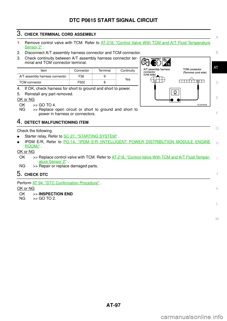
3.CHECK TERMINAL CORD ASSEMBLY
1. Remove control valve with TCM. Refer toAT- 2 1 8 , "
Control Valve With TCM and A/T Fluid Temperature
Sensor 2".
2. Disconnect A/T assembly harness connector and TCM connector.
3. Check continuity between A/T assembly harness connector ter-
minal and TCM connector terminal.
4. If OK, check harness for short to ground and short to power.
5. Reinstall any part removed.
OK or NG
OK >> GO TO 4.
NG >> Replace open circuit or short to ground and short to
power in harness or connectors.
4.DETECT MALFUNCTIONING ITEM
Check the following.
lStarter relay, Refer toSC-27, "STARTING SYSTEM".
lIPDM E/R, Refer toPG-14, "IPDM E/R (INTELLIGENT POWER DISTRIBUTION MODULE ENGINE
ROOM)".
OK or NG
OK >> Replace control valve with TCM. Refer toAT- 2 1 8 , "Control Valve With TCM and A/T Fluid Temper-
ature Sensor 2".
NG >> Repair or replace damaged parts.
5.CHECK DTC
PerformAT-94, "
DTC Confirmation Procedure".
OK or NG
OK >>INSPECTION END
NG >> GO TO 2.
Item Connector Terminal Continuity
A/T assembly harness connector F36 9
Ye s
TCM connector F502 8
SCIA5440E
Page 185 of 3171

TROUBLE DIAGNOSIS FOR SYMPTOMS
AT-177
D
E
F
G
H
I
J
K
L
MA
B
AT
Data are reference value and are measured between each terminal and ground.
OD OFF Indicator Lamp Does Not Come OnECS00G2B
SYMPTOM:
OD OFF indicator lamp does not come on for about 2 seconds when turning ignition switch ON.
DIAGNOSTIC PROCEDURE
1.CHECK CAN COMMUNICATION LINE
Perform self-diagnosis. Refer toAT-80, "
SELF-DIAGNOSTIC RESULT MODE",AT-89, "Diagnostic Procedure
Without CONSULT-II".
Is a malfunction in the CAN communication indicated in the results?
YES >> Check CAN communication line. Refer toAT-91, "DTC U1000 CAN COMMUNICATION LINE".
NO >> GO TO 2.
2.CHECK OD OFF INDICATOR LAMP CIRCUIT
Check combination meter. Refer toDI-4, "
COMBINATION METERS".
OK or NG
OK >> GO TO 3
NG >> Repair or replace damaged parts.
3.CHECK TCM POWER SUPPLY AND GROUND CIRCUIT
Check TCM power supply and ground circuit. Refer toAT- 1 6 4 , "
MAIN POWER SUPPLY AND GROUND CIR-
CUIT".
OK or NG
OK >>INSPECTION END
NG >> Repair or replace damaged parts.
Engine Cannot Be Started in “P” or “N” PositionECS00G2C
SYMPTOM:
lEngine cannot be started with selector lever in “P” or “N” position.
lEngine can be started with selector lever in “R”, “D”, “3”, “2” or “1” position.
DIAGNOSTIC PROCEDURE
1.CHECK SELF-DIAGNOSIS RESULTS
Perform self-diagnosis. Refer toAT-80, "
SELF-DIAGNOSTIC RESULT MODE",AT-89, "Diagnostic Procedure
Without CONSULT-II".
Do the self-diagnosis results indicate PNP switch?
YES >> Check malfunctioning system. Refer toAT-99, "DTC P0705 PARK/NEUTRAL POSITION
SWITCH".
NO >> GO TO 2.
TerminalWire
colorItem Condition Data (Approx.)
3 L CAN-H – –
4GRK-line (CONSULT-
II signal)The terminal is connected to the data link connector for CONSULT-II. –
7LGBack-up lamp
relaySelector lever in “R” position. 0V
Selector lever in other positions. Battery voltage
8 P CAN-L – –
9BRStarterrelaySelector lever in “N” or “P” position. Battery voltage
Selector lever in other positions. 0V
Page 354 of 3171

ATC-20
REFRIGERATION SYSTEM
REFRIGERATION SYSTEM
PFP:KA990
Refrigerant CycleEJS006AW
REFRIGERANT FLOW
The refrigerant flows in the standard pattern, that is, through the compressor, the condenser with liquid tank,
through the evaporator, and back to the compressor. The refrigerant evaporation through the evaporator is
controlled by an externally equalized expansion valve, located inside the evaporator case.
FREEZE PROTECTION
Under usual operating conditions, when the A/C is switched ON, the compressor runs continuously, and the
evaporator pressure, and therefore, temperature is controlled by the V-6 variable displacement compressor to
prevent freeze up.
Refrigerant System ProtectionEJS006AX
REFRIGERANT PRESSURE SENSOR
The refrigerant system is protected against excessively high or low pressures by the refrigerant pressure sen-
sor, located on the condenser. If the system pressure rises above or falls below the specifications, the refriger-
ant pressure sensor detects the pressure inside the refrigerant line and sends a voltage signal to the ECM.
The ECM de-energizes the A/C relay to disengage the magnetic compressor clutch when pressure on the high
pressure side detected by refrigerant pressure sensor is over about 2,746 kPa (28 kg/cm
2, 398 psi), or below
about 120 kPa (1.22 kg/cm
2,17.4psi).
Page 361 of 3171
AIR CONDITIONER CONTROL
ATC-27
C
D
E
F
G
H
I
K
L
MA
B
AT C
MAGNET CLUTCH CONTROL
When A/C switch or DEF switch is pressed, front air control inputs compressor ON signal to BCM.
BCM sends compressor ON signal to ECM, via CAN communication line.
ECM judges whether compressor can be turned ON, based on each sensor status (refrigerant pressure sen-
sor signal, throttle angle sensor, etc.). If it judges compressor can be turned ON, it sends compressor ON sig-
nal to IPDM E/R, via CAN communication line.
Upon receipt of compressor ON signal from ECM, IPDM E/R turns air conditioner relay ON to operate com-
pressor.
SELF-DIAGNOSTIC SYSTEM
The self-diagnostic system is built into the front air control to quickly locate the cause of symptoms. Refer to
AT C - 5 5 , "
A/C System Self-diagnosis Function".
WJIA1163E
Page 388 of 3171

ATC-54
TROUBLE DIAGNOSIS
19 GR Power supply for BAT - - Battery voltage
20 B Ground - - 0V
21 V Mode door motor feedback ON - 0 - 5V
22 SB Air mix door motor (Driver) feedback ON - 0 - 5V
23 G Sensor power ON - 5V
26 P Sensor return ON - 0V
27 R In-vehicle sensor signal ON - 0 - 5V
28 W Ambient sensor ON - 0 - 5V
29 G Optical sensor (Driver) ON - 0 - 5V
31 PPTC heater relay 1
(LHD models)ONRelay ON Battery voltage
Relay OFF 0V
32 V Variable blower control ON - 0 - 5V
33 BR In-vehicle sensor motor (+) ON - Battery voltage
34 O In-vehicle sensor motor (-) ON - 0V
35 LG Fan ON signalON Blower switch OFF 5V
ON Blower switch ON 0V
36 SBAir mix door motor (Passenger)
feedbackON - 0 - 5V
37 GR Optical sensor (Passenger) ON - 0 - 5V
38 B Blower request ONBlower motor OFF Battery voltage
Blower motor ON 0V
40 LGPTC heater relay 2
(LHD models)ONRelay ON Battery voltage
Relay OFF 0V
41 L CAN-H ON - 0 - 5V
42 P CAN-L ON - 0 - 5V
43 BRPTC heater relay 3
(LHD models)ONRelay ON Battery voltage
Relay OFF 0V
44 R Mirror heater (LHD models) ONHeater OFF 0V
Heater ON Battery voltage Te r m i -
nal No.Wire
colorItemIgnition
switchConditionVoltage (V)
(Approx.)