2005 NISSAN NAVARA ignition
[x] Cancel search: ignitionPage 2973 of 3171

TF-6
PRECAUTIONS
If 4WD shift indicator lamp and 4LO indicator lamp do not indicate proper pattern, install new transfer con-
trol unit and retry the above check.
PrecautionsEDS0031B
lBefore connecting or disconnecting the transfer control unit harness connector, turn ignition
switch “OFF” and disconnect the battery cables. Battery voltage is applied to transfer control unit
even if ignition switch is turned “OFF”.
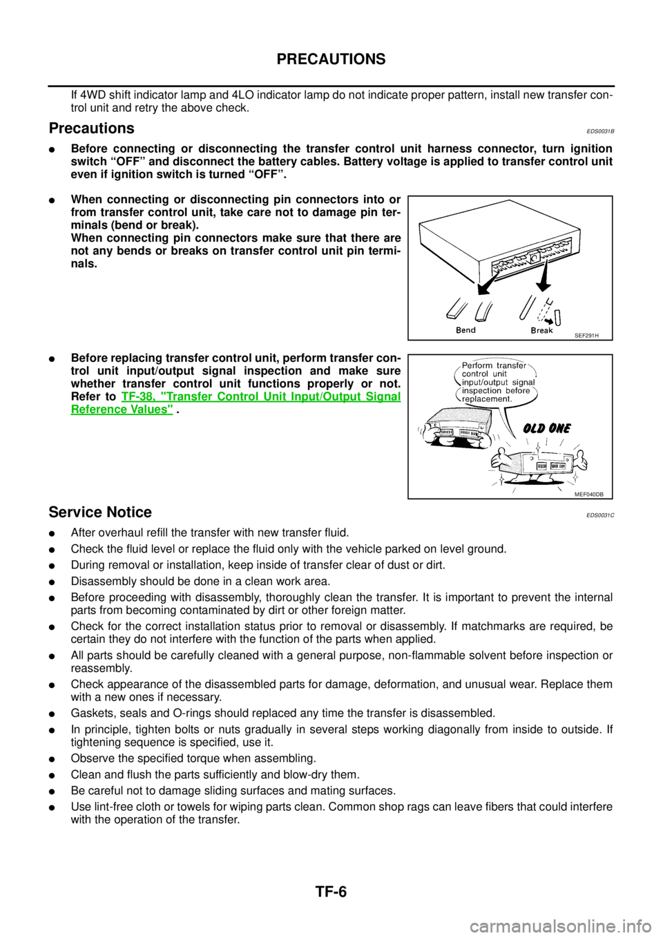
lWhen connecting or disconnecting pin connectors into or
from transfer control unit, take care not to damage pin ter-
minals (bend or break).
When connecting pin connectors make sure that there are
not any bends or breaks on transfer control unit pin termi-
nals.
lBefore replacing transfer control unit, perform transfer con-
trol unit input/output signal inspection and make sure
whether transfer control unit functions properly or not.
Refer toTF-38, "
Transfer Control Unit Input/Output Signal
Reference Values".
Service NoticeEDS0031C
lAfter overhaul refill the transfer with new transfer fluid.
lCheck the fluid level or replace the fluid only with the vehicle parked on level ground.
lDuring removal or installation, keep inside of transfer clear of dust or dirt.
lDisassemblyshouldbedoneinacleanworkarea.
lBefore proceeding with disassembly, thoroughly clean the transfer. It is important to prevent the internal
parts from becoming contaminated by dirt or other foreign matter.
lCheck for the correct installation status prior to removal or disassembly. If matchmarks are required, be
certain they do not interfere with the function of the parts when applied.
lAll parts should be carefully cleaned with a general purpose, non-flammable solvent before inspection or
reassembly.
lCheck appearance of the disassembled parts for damage, deformation, and unusual wear. Replace them
with a new ones if necessary.
lGaskets, seals and O-rings should replaced any time the transfer is disassembled.
lIn principle, tighten bolts or nuts gradually in several steps working diagonally from inside to outside. If
tightening sequence is specified, use it.
lObserve the specified torque when assembling.
lClean and flush the parts sufficiently and blow-dry them.
lBe careful not to damage sliding surfaces and mating surfaces.
lUse lint-free cloth or towels for wiping parts clean. Common shop rags can leave fibers that could interfere
with the operation of the transfer.
SEF291H
MEF040DB
Page 2983 of 3171

TF-16
4WD SYSTEM
4WD SHIFT SWITCH AND INDICATOR LAMP
4WD Shift Switch
4WD shift switch is able to select from 2WD, 4H or 4LO.
4WD Shift Indicator Lamp
lDisplays driving conditions selected by 4WD shift switch with front, rear and center indicators, while
engine is running. (When shifting from 4H to 4LO, 4LO indicator lamp also turns on. And when 4WD warn-
ing lamp is turned on, all 4WD shift indicator lamps are turned off.)
lTurns ON when ignition switch is turned ON, for purpose of lamp check. Turns OFF approximately 1 sec-
ondaftertheenginestartsifsystemisnormal.
4LO Indicator Lamp
lDisplays 4LO condition while engine is running. 4LO indicator lamp flashes if transfer gear does not shift
completely under 4HÛ4LO. In this condition, transfer may be under neutral condition and A/T parking
mechanism may not operate.
lTurns ON when ignition switch is turned ON, for purpose of lamp check. Turns OFF approximately 1 sec-
ondaftertheenginestartsifsystemisnormal.
SDIA3290E
Page 2984 of 3171

4WD SYSTEM
TF-17
C
E
F
G
H
I
J
K
L
MA
B
TF
4WD WARNING LAMP
Turns ON or flashes when there is a malfunction in 4WD system.
Also turns ON when ignition switch is turned ON, for purpose of lamp check. Turns OFF approximately 1 sec-
ond after the engine starts if system is normal.
4WD Warning Lamp Indication
NOTE:
4WD warning lamp is turned on when the following one or more parts are malfunctioning.
lVehicle speed signal
[from ABS actuator and electric unit (control unit)]
lCAN communication line
lAD converter
lEngine speed signal
l4WD shift switch
lWait detection switch
lActuator motor
lTransfer control device
lTransfer shut off relay
lTransfer shift relay
lPNP switch signal
ATP WARNING LAMP (A/T MODELS)
When A/T selector lever is in “P” position, vehicle may move because A/T parking mechanism does not oper-
ate when transfer is under neutral condition. ATP warning lamp is turned on to indicate this condition to the
driver.
Condition 4WD warning lamp
Lamp checkTurns ON when ignition switch is turned ON.
Turns OFF after engine start.
4WD system malfunctionON
(For indicated malfunction items, see the “NOTE”)
During self-diagnosis Flashes at malfunction mode.
Large difference in diameter of front/
rear tiresSlow flashing: 1 time/2 seconds
(Continues to flash until ignition switch is turned OFF)
Other than above (system normal) OFF
Page 3005 of 3171

TF-38
TROUBLE DIAGNOSIS
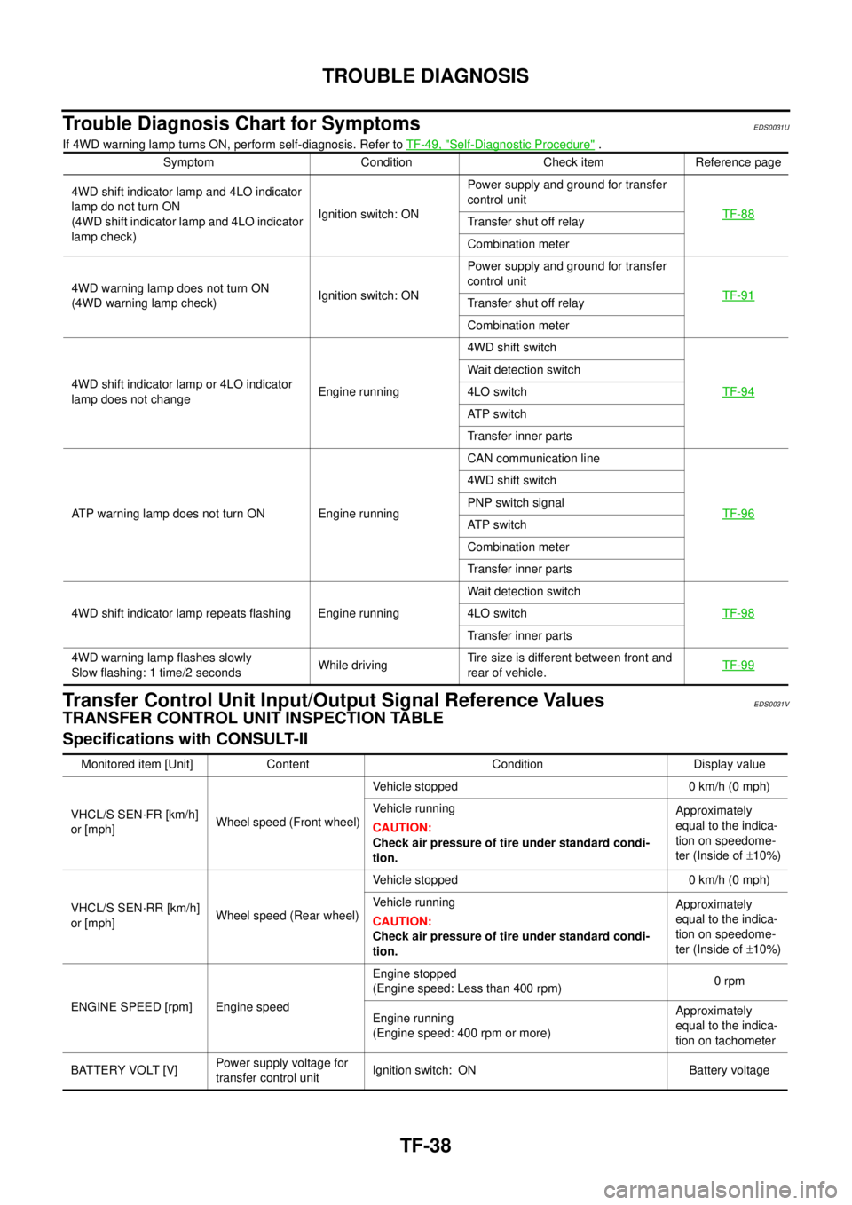
Trouble Diagnosis Chart for Symptoms
EDS0031U
If 4WD warning lamp turns ON, perform self-diagnosis. Refer toTF-49, "Self-Diagnostic Procedure".
Transfer Control Unit Input/Output Signal Reference ValuesEDS0031V
TRANSFER CONTROL UNIT INSPECTION TABLE
Specifications with CONSULT-II
Symptom Condition Check item Reference page
4WD shift indicator lamp and 4LO indicator
lamp do not turn ON
(4WD shift indicator lamp and 4LO indicator
lamp check)Ignition switch: ONPower supply and ground for transfer
control unit
TF-88
Transfer shut off relay
Combination meter
4WD warning lamp does not turn ON
(4WD warning lamp check)Ignition switch: ONPower supply and ground for transfer
control unit
TF-91
Transfer shut off relay
Combination meter
4WD shift indicator lamp or 4LO indicator
lamp does not changeEngine running4WD shift switch
TF-94
Wait detection switch
4LO switch
AT P s w i t c h
Transfer inner parts
ATP warning lamp does not turn ON Engine runningCAN communication line
TF-96
4WD shift switch
PNP switch signal
AT P s w i t c h
Combination meter
Transfer inner parts
4WD shift indicator lamp repeats flashing Engine runningWait detection switch
TF-98
4LO switch
Transfer inner parts
4WD warning lamp flashes slowly
Slow flashing: 1 time/2 secondsWhile drivingTire size is different between front and
rear of vehicle.TF-99
Monitored item [Unit] Content Condition Display value
VHCL/S SEN·FR [km/h]
or [mph]Wheel speed (Front wheel)Vehicle stopped 0 km/h (0 mph)
Vehicle running
CAUTION:
Check air pressure of tire under standard condi-
tion.Approximately
equal to the indica-
tion on speedome-
ter (Inside of±10%)
VHCL/S SEN·RR [km/h]
or [mph]Wheel speed (Rear wheel)Vehicle stopped 0 km/h (0 mph)
Vehicle running
CAUTION:
Check air pressure of tire under standard condi-
tion.Approximately
equal to the indica-
tion on speedome-
ter (Inside of±10%)
ENGINE SPEED [rpm] Engine speedEngine stopped
(Engine speed: Less than 400 rpm)0rpm
Engine running
(Engine speed: 400 rpm or more)Approximately
equal to the indica-
tion on tachometer
BATTERY VOLT [V]Power supply voltage for
transfer control unitIgnition switch: ON Battery voltage
Page 3008 of 3171

TROUBLE DIAGNOSIS
TF-41
C
E
F
G
H
I
J
K
L
MA
B
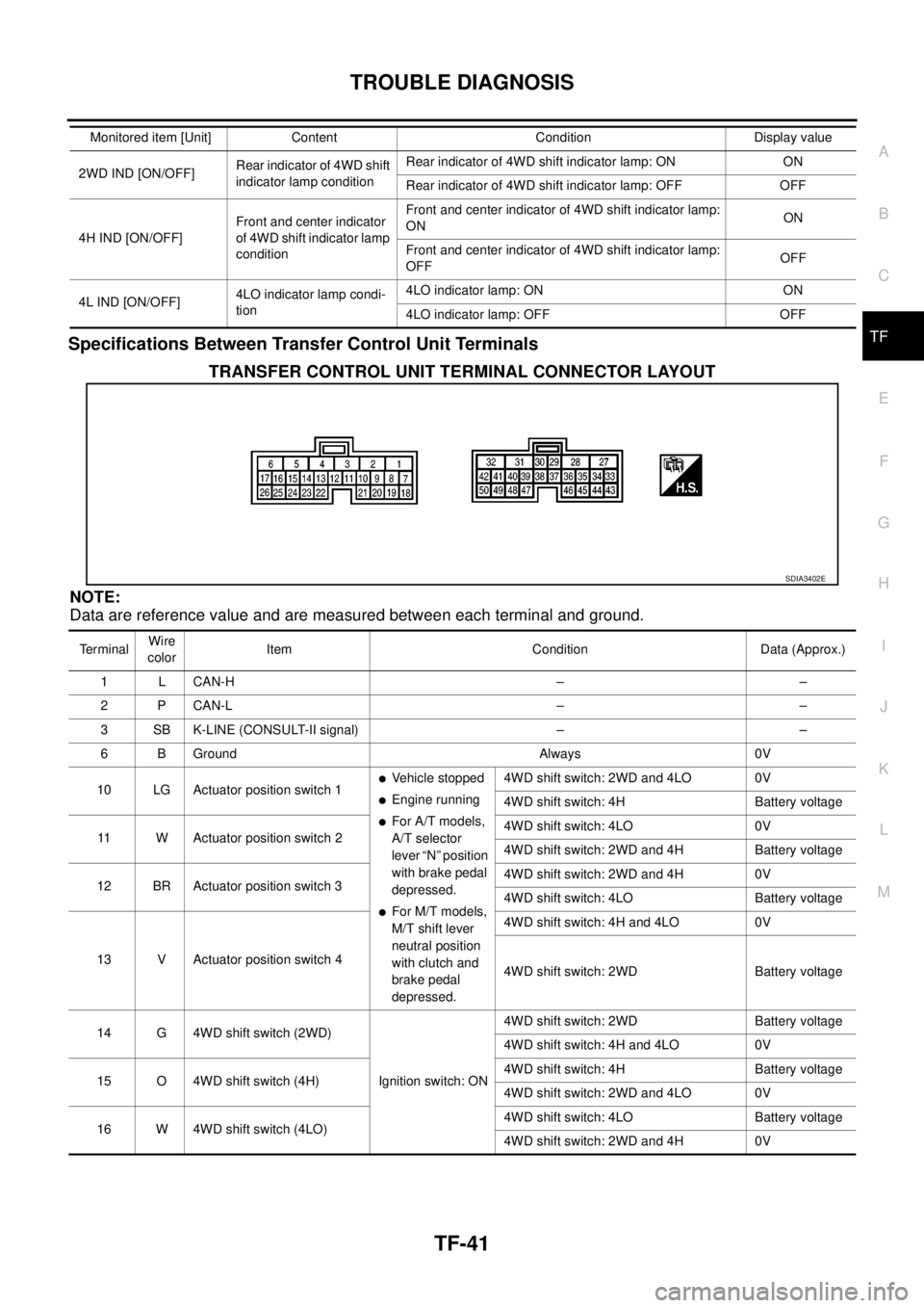
TFSpecifications Between Transfer Control Unit Terminals
TRANSFER CONTROL UNIT TERMINAL CONNECTOR LAYOUT
NOTE:
Data are reference value and are measured between each terminal and ground.
2WD IND [ON/OFF]Rear indicator of 4WD shift
indicator lamp conditionRear indicator of 4WD shift indicator lamp: ON ON
Rear indicator of 4WD shift indicator lamp: OFF OFF
4H IND [ON/OFF]Front and center indicator
of 4WD shift indicator lamp
conditionFront and center indicator of 4WD shift indicator lamp:
ONON
Front and center indicator of 4WD shift indicator lamp:
OFFOFF
4L IND [ON/OFF]4LO indicator lamp condi-
tion4LO indicator lamp: ON ON
4LO indicator lamp: OFF OFF Monitored item [Unit] Content Condition Display value
SDIA3402E
TerminalWire
colorItem Condition Data (Approx.)
1 L CAN-H – –
2 P CAN-L – –
3 SB K-LINE (CONSULT-II signal) – –
6 B Ground Always 0V
10 LG Actuator position switch 1
lVehicle stopped
lEngine running
lFor A/T models,
A/T selector
lever “N” position
with brake pedal
depressed.
lFor M/T models,
M/T shift lever
neutral position
with clutch and
brake pedal
depressed.4WD shift switch: 2WD and 4LO 0V
4WD shift switch: 4H Battery voltage
11 W Actuator position switch 24WD shift switch: 4LO 0V
4WD shift switch: 2WD and 4H Battery voltage
12 BR Actuator position switch 34WD shift switch: 2WD and 4H 0V
4WD shift switch: 4LO Battery voltage
13 V Actuator position switch 44WD shift switch: 4H and 4LO 0V
4WD shift switch: 2WD Battery voltage
14 G 4WD shift switch (2WD)
Ignition switch: ON4WD shift switch: 2WD Battery voltage
4WD shift switch: 4H and 4LO 0V
15 O 4WD shift switch (4H)4WD shift switch: 4H Battery voltage
4WD shift switch: 2WD and 4LO 0V
16 W 4WD shift switch (4LO)4WD shift switch: 4LO Battery voltage
4WD shift switch: 2WD and 4H 0V
Page 3009 of 3171

TF-42
TROUBLE DIAGNOSIS
17 O Wait detection switch
lVehicle stopped
lEngine running
lFor A/T models,
A/T selector
lever “N” position
with brake pedal
depressed.
lFor M/T models,
M/T shift lever
neutral position
with clutch and
brake pedal
depressed.4WD shift switch: 4H and 4LO 0V
4WD shift switch: 2WD Battery voltage
18 B Ground Always 0V
19 RPower supply
(Memory back-up)Ignition switch: ON
Battery voltage
Ignition switch: OFF
23 R ATP switch
lVehicle stopped
lEngine running
lFor A/T models,
A/T selector
lever “N” position
with brake pedal
depressed.
lFor M/T models,
M/T shift lever
neutral position
with clutch and
brake pedal
depressed.4WD shift switch:
4H to 4LO or 4LO to 4H
(While actuator motor is operating.)0V
Except the above Battery voltage
24 Y 4LO switch
lVehicle stopped
lEngine running
lFor A/T models,
A/T selector
lever “N” position
with brake pedal
depressed.
lFor M/T models,
M/T shift lever
neutral position
with clutch and
brake pedal
depressed.4WD shift switch: 4LO 0V
Except the above Battery voltage
25 LG Ignition switch monitorIgnition switch: ON Battery voltage
Ignition switch: OFF 0V
27 L Actuator motor power supplyIgnition switch: ON Battery voltage
Ignition switch: OFF
(5 seconds after ignition switch is turned OFF)0V Te r m i n a lWire
colorItem Condition Data (Approx.)
Page 3010 of 3171

TROUBLE DIAGNOSIS
TF-43
C
E
F
G
H
I
J
K
L
MA
B
TF
28 BR Actuator motor (+)
lVehicle stopped
lEngine running
lFor A/T models,
A/T selector
lever “N” position
with brake pedal
depressed.
lFor M/T models,
M/T shift lever
neutral position
with clutch and
brake pedal
depressed.When 4WD shift switch is operated
(while actuator motor is operating)Battery voltage
®0V
When 4WD shift switch is not operated 0V
31 G Actuator motor (-) Always 0V
32 B Ground Always 0V
33
(For M/T
models)P Park/Neutral position switch Ignition switch: ONM/T shift lever neutral position 0V
Except the above Battery voltage
35 V4WD shift indicator lamp
(Rear indicator)
Engine runningRear indicator of 4WD shift indicator
lamp: ON0V
Rear indicator of 4WD shift indicator
lamp: OFFBattery voltage
36 BR4WD shift indicator lamp
(Front and center indicator)Front and center indicator of 4WD shift
indicator lamp: ON0V
Front and center indicator of 4WD shift
indicator lamp: OFFBattery voltage
37 Y 4LO indicator lamp4LO indicator lamp: ON 0V
4LO indicator lamp: OFF Battery voltage
38 P 4WD warning lamp4WD warning lamp: ON 0V
4WD warning lamp: OFF Battery voltage
39
(For A/T
models)LG ATP warning lamp
lVehicle stopped
lEngine running
lA/T selector
lever “P” position
lBrake pedal
depressed4WD shift switch:
4H to 4LO or 4LO to 4H
(While actuator motor is operating.)Battery voltage
Except the above 0V
40 V Transfer shut off relayIgnition switch: ON 0V
Ignition switch: OFF
(5 seconds after ignition switch is turned OFF)Battery voltage
42 LG Transfer shift high relay
lVehicle stopped
lEngine running
lFor A/T models,
A/T selector
lever “N” position
with brake pedal
depressed.
lFor M/T models,
M/T shift lever
neutral position
with clutch and
brake pedal
depressed.4WD shift switch:
2WD to 4H or 4H to 4LO or 2WD to 4LO0V
Except the above Battery voltage TerminalWire
colorItem Condition Data (Approx.)
Page 3011 of 3171

TF-44
TROUBLE DIAGNOSIS
CAUTION:
When using a circuit tester to measure voltage for inspection, be sure not to extend forcibly any connector terminals.
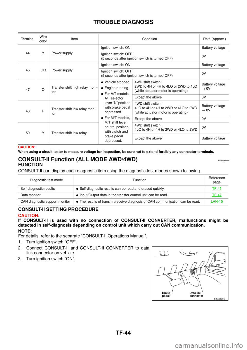
CONSULT-II Function (ALL MODE AWD/4WD)EDS0031W
FUNCTION
CONSULT-II can display each diagnostic item using the diagnostic test modes shown following.
CONSULT-II SETTING PROCEDURE
CAUTION:
If CONSULT-II is used with no connection of CONSULT-II CONVERTER, malfunctions might be
detected in self-diagnosis depending on control unit which carry out CAN communication.
NOTE:
For details, refer to the separate “CONSULT-II Operations Manual”.
1. Turn ignition switch “OFF”.
2. Connect CONSULT-II and CONSULT-II CONVERTER to data
link connector on vehicle.
3. Turn ignition switch “ON”.
44 Y Power supplyIgnition switch: ON Battery voltage
Ignition switch: OFF
(5 seconds after ignition switch is turned OFF)0V
45 GR Power supplyIgnition switch: ON Battery voltage
Ignition switch: OFF
(5 seconds after ignition switch is turned OFF)0V
47 OTransfer shift high relay moni-
tor
lVehicle stopped
lEngine running
lFor A/T models,
A/T selector
lever “N” position
with brake pedal
depressed.
lFor M/T models,
M/T shift lever
neutral position
with clutch and
brake pedal
depressed.4WD shift switch:
2WD to 4H or 4H to 4LO or 2WD to 4LO
(while actuator motor is operating)Battery voltage
®0V
Except the above 0V
48 RTransfer shift low relay moni-
tor4WD shift switch:
4LO to 4H or 4H to 2WD or 4LO to 2WD
(while actuator motor is operating)Battery voltage
®0V
Except the above 0V
50 Y Transfer shift low relay4WD shift switch:
4LO to 4H or 4H to 2WD or 4LO to 2WD0V
Except the above Battery voltage Te r m i n a lWire
colorItem Condition Data (Approx.)
Diagnostic test mode FunctionReference
page
Self-diagnostic results
lSelf-diagnostic results can be read and erased quickly.TF-45
Data monitorlInput/Output data in the transfer control unit can be read.TF-47
CAN diagnostic support monitorlThe results of transmit/receive diagnosis of CAN communication can be read.LAN-15
BBIA0538E