2005 NISSAN NAVARA ignition
[x] Cancel search: ignitionPage 2823 of 3171
SB-6
SEAT BELTS
REMOVALOFSEATBELTRETRACTOR
CAUTION:
lBefore servicing SRS, turn the ignition switch off, disconnect both battery cables and wait at least
3 minutes.
1. Remove the center pillar upper/lower finishers. Refer toEI-33, "
BODY SIDE TRIM".
2. Remove the seat belt retractor and belt bolts and assembly.
lOn RH side, disconnect the seat belt tension sensor.
3. Disconnect the seat belt pre-tensioner electrical connector.
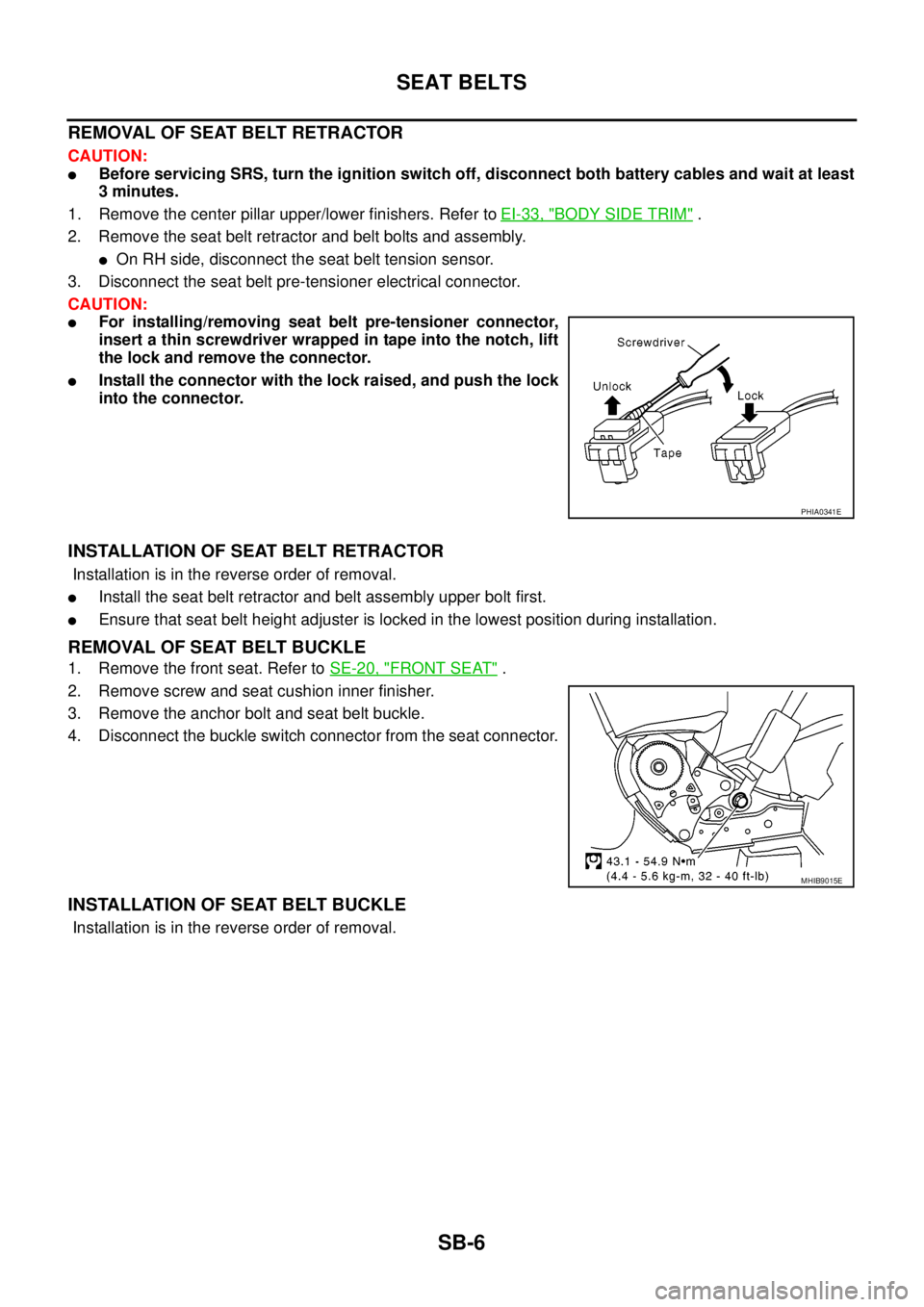
CAUTION:
lFor installing/removing seat belt pre-tensioner connector,
insert a thin screwdriver wrapped in tape into the notch, lift
the lock and remove the connector.
lInstall the connector with the lock raised, and push the lock
into the connector.
INSTALLATION OF SEAT BELT RETRACTOR
Installation is in the reverse order of removal.
lInstall the seat belt retractor and belt assembly upper bolt first.
lEnsure that seat belt height adjuster is locked in the lowest position during installation.
REMOVAL OF SEAT BELT BUCKLE
1. Remove the front seat. Refer toSE-20, "FRONT SEAT".
2. Remove screw and seat cushion inner finisher.
3. Remove the anchor bolt and seat belt buckle.
4. Disconnect the buckle switch connector from the seat connector.
INSTALLATION OF SEAT BELT BUCKLE
Installation is in the reverse order of removal.
PHIA0341E
MHIB9015E
Page 2828 of 3171
SEAT BELTS
SB-11
C
D
E
F
G
I
J
K
L
MA
B
SB
Seat Belt InspectionEHS0026A
AFTER A COLLISION
WARNING:
Inspect all seat belt assemblies including retractors and attaching hardware after any collision.
NISSAN recommends that all seat belt assemblies in use during a collision be replaced unless the col-
lision was minor and the belts show no damage and continue to operate properly. Failure to do so
could result in serious personal injury in an accident. Seat belt assemblies not in use during a colli-
sion should also be replaced if either damage or improper operation is noted. Seat belt pre-tensioners
should be replaced even if the seat belts are not in use during a frontal collision in which the air bags
are deployed.
Replace any seat belt assembly (including anchor bolts) if:
lThe seat belt was in use at the time of a collision (except for minor collisions and the belts, retractors and
buckles show no damage and continue to operate properly).
lThe seat belt was damaged in an accident. (i.e. torn webbing, bent retractor or guide).
lThe seat belt attaching point was damaged in an accident. Inspect the seat belt attaching area for damage
or distortion and repair as necessary before installing a new seat belt assembly.
lAnchor bolts are deformed or worn out.
lThe seat belt pre-tensioner should be replaced even if the seat belts are not in use during the collision in
which the air bags are deployed.
PRELIMINARY CHECKS
1. Check the seat belt warning lamp for proper operation as follows:
a. Switch ignition ON. The seat belt warning lamp should illuminate.
b. Fasten driver's seat belt. The seat belt warning lamp should go out. If warning lamp remains illuminated,
Refer toDI-28, "
WARNING LAMPS".
2. If the air bag warning lamp is blinking, conduct self-diagnosis using CONSULT-II, and air bag warning
lamp. Refer toSRS-18, "
SRS Operation Check".
3. Check that the seat belt retractor, seat belt anchor and buckle bolts are securely attached.
4. Check the shoulder seat belt guide and shoulder belt height adjuster for front seats. Ensure guide swivels
freely and that belt lays flat and does not bind in guide. Ensure height adjuster operates properly and
holds securely.
5. Check retractor operation:
a. Fully extend the seat belt webbing and check for twists, tears or other damage.
b. Allow the seat belt to retract. Ensure that belt returns smoothly and completely into the retractor. If the
seat belt does not return smoothly, wipe the inside of the loops with a clean paper cloth, because dirt built
up in the loops of the upper anchors can cause the seat belts to retract slowly.
c. Fasten the seat belt. Check the seat belt returns smoothly and completely to the retractor. If the belt does
not return smoothly, the cause may be an accumulation of dust or dirt. Use the “SEAT BELT TAPE SET”
and perform the following steps.
Inspect the front seat belt through-anchor:
1. Pull the seat belt out to a length of 500 mm (19.69 in) or more.
2. Use a clip or other device to hold the seat belt at the center pillar belt opening.
3. Pass a thin wire through the through-anchor belt opening. Hold both ends of the wire and pull taut while
moving it up and down several times along the belt opening surface to remove dirt.
4. Any dirt that cannot be removed with the wire can be removed by cleaning the opening with a clean
cloth.
5. Apply tape at the point where the belt contacts the through-anchor belt opening.
NOTE:
Apply the tape so that there is no looseness or wrinkling.
6. Remove the clip holding the seat belt and check that the belt returns smoothly.
7. Repeat steps above as necessary to check the other seat belts.
Page 2847 of 3171

SC-14
CHARGING SYSTEM
CHARGING SYSTEM
PFP:00011
System DescriptionEKS00MZA
The alternator provides DC voltage to operate the vehicle's electrical system and to keep the battery charged.
The voltage output is controlled by the IC regulator.
Power is supplied at all times to alternator terminal 4 through:
l15A fuse (No. 30, located in the fuse and fusible link box).
Terminal 1 supplies power to charge the battery and operate the vehicle's electrical system. Output voltage is
controlled by the IC regulator at terminal 4 detecting the input voltage. The charging circuit is protected by the
140A fusible link (letter "A", located in the fuse and fusible link box) .
The alternator is grounded to the engine block.
With the ignition switch in the ON or START position, power is supplied
l10A fuse [No. 14, located in the fuse block (J/B)]
lto combination meter terminal 16 for the charge warning lamp.
Ground is supplied With power and ground supplied
lto terminal 2 of the combination meter
lthrough terminal 3 of the alternator.
If the charge warning lamp illuminates with the engine running, a fault is indicated.
The charge warning lamp will illuminate. When the alternator is providing sufficient voltage with the engine
running, the ground is opened and the charge warning lamp will go off.
Page 2849 of 3171
SC-16
CHARGING SYSTEM
Trouble Diagnosis
EKS00MZD
DIAGNOSIS PROCEDURE
1. Check malfunction symptoms or customer's remarks.
2. Perform pre-diagnosis inspection. Refer toSC-16, "
PRE-DIAGNOSIS INSPECTION".
3. Perform trouble diagnosis for each trouble symptom. Refer toSC-16, "
DIAGNOSIS CHART BY SYMP-
TOM"
4. Repair or replace parts indicated inspection flow based on the charge warning lamp. Refer toSC-16,
"INSPECTION FLOW BY CHARGE WARNING LAMP".
5. End
PRE-DIAGNOSIS INSPECTION
1. Perform alternator belt inspection. Refer toEM-12, "DRIVE BELTS".
2. Inspect battery.
3. Check alternator terminal 1 for loose or improper connection.
4. Check alternator connector 4 and 3 terminals for loose connection, disconnection and bend.
5. Check connecting condition of harness for charging system harness (fusible link terminal and battery ter-
minal).
6. After performing 1 to 5 above, go to trouble diagnosis for symptoms. Refer toSC-16, "
DIAGNOSIS
CHART BY SYMPTOM".
DIAGNOSIS CHART BY SYMPTOM
INSPECTION FLOW BY CHARGE WARNING LAMP
1.CHARGE WARNING LAMP INSPECTION
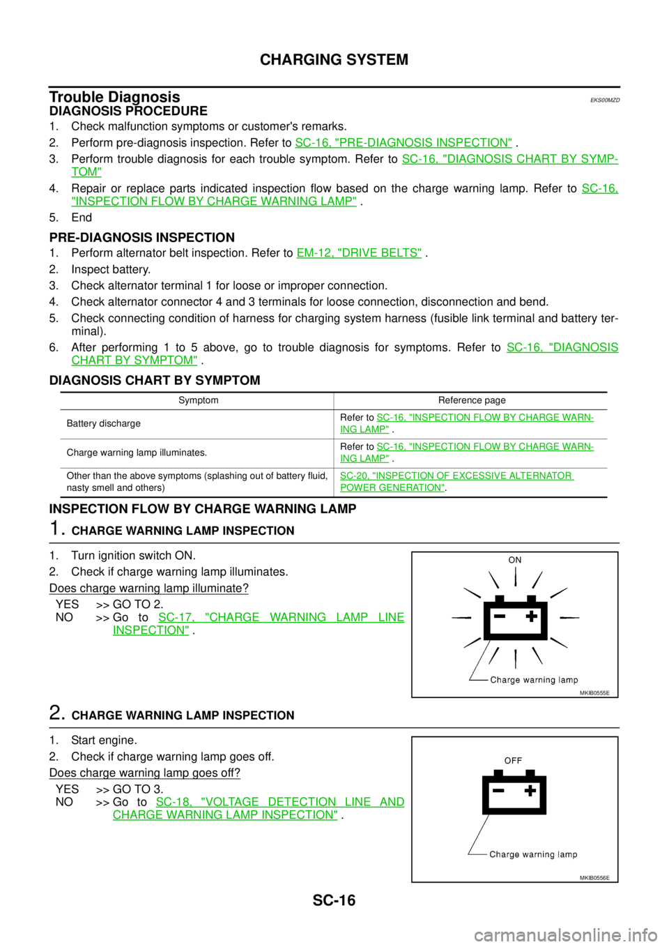
1. Turn ignition switch ON.
2. Check if charge warning lamp illuminates.
Does charge warning lamp illuminate?
YES >> GO TO 2.
NO >> Go toSC-17, "
CHARGE WARNING LAMP LINE
INSPECTION".
2.CHARGE WARNING LAMP INSPECTION
1. Start engine.
2. Check if charge warning lamp goes off.
Does charge warning lamp goes off?
YES >> GO TO 3.
NO >> Go toSC-18, "
VOLTAGE DETECTION LINE AND
CHARGE WARNING LAMP INSPECTION".
Symptom Reference page
Battery dischargeRefer toSC-16, "
INSPECTION FLOW BY CHARGE WARN-
ING LAMP".
Charge warning lamp illuminates.Refer toSC-16, "
INSPECTION FLOW BY CHARGE WARN-
ING LAMP".
Other than the above symptoms (splashing out of battery fluid,
nasty smell and others)SC-20, "
INSPECTION OF EXCESSIVE ALTERNATOR
POWER GENERATION".
MKIB0555E
MKIB0556E
Page 2850 of 3171
CHARGING SYSTEM
SC-17
C
D
E
F
G
H
I
J
L
MA
B
SC
3.CHARGE WARNING LAMP INSPECTION
1. Set engine speed at 2,500 rpm.
2. Check if charge warning lamp illuminates.
Does charge warning lamp illuminate?
YES >> Go toSC-20, "INSPECTION OF EXCESSIVE ALTER-
NATOR POWER GENERATION".
NO >> Go toSC-20, "
INSPECTION OF INSUFFICIENT
ALTERNATOR POWER GENERATION".
CHARGE WARNING LAMP LINE INSPECTION
CAUTION:
If open circuit is detected in alternator connector terminal 3, alternator cannot start generating.
INSPECTION PROCEDURE
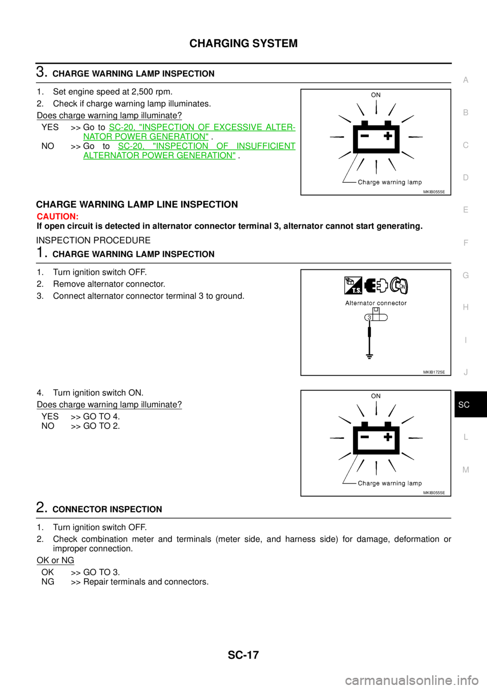
1.CHARGE WARNING LAMP INSPECTION
1. Turn ignition switch OFF.
2. Remove alternator connector.
3. Connect alternator connector terminal 3 to ground.
4. Turn ignition switch ON.
Does charge warning lamp illuminate?
YES >> GO TO 4.
NO >> GO TO 2.
2.CONNECTOR INSPECTION
1. Turn ignition switch OFF.
2. Check combination meter and terminals (meter side, and harness side) for damage, deformation or
improper connection.
OK or NG
OK >> GO TO 3.
NG >> Repair terminals and connectors.
MKIB0555E
MKIB1725E
MKIB0555E
Page 2851 of 3171
SC-18
CHARGING SYSTEM
3.CONTINUITY INSPECTION
1. Disconnect combination meter connector.
2. Check continuity between combination meter connector terminal 2 and alternator connector terminal 3.
OK or NG
OK >> Replace combination meter. (Do not replace alternator, since it is normal.)
NG >> Repair the harnesses or connectors. (Do not replace alternator, since it is normal.)
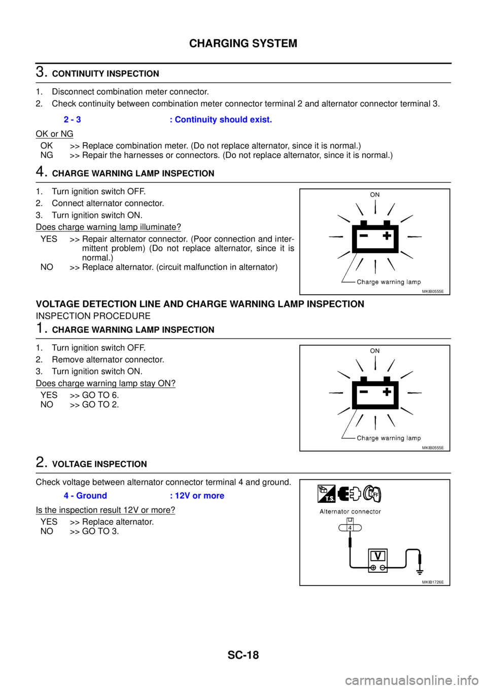
4.CHARGE WARNING LAMP INSPECTION
1. Turn ignition switch OFF.
2. Connect alternator connector.
3. Turn ignition switch ON.
Does charge warning lamp illuminate?
YES >> Repair alternator connector. (Poor connection and inter-
mittent problem) (Do not replace alternator, since it is
normal.)
NO >> Replace alternator. (circuit malfunction in alternator)
VOLTAGE DETECTION LINE AND CHARGE WARNING LAMP INSPECTION
INSPECTION PROCEDURE
1.CHARGE WARNING LAMP INSPECTION
1. Turn ignition switch OFF.
2. Remove alternator connector.
3. Turn ignition switch ON.
Does charge warning lamp stay ON?
YES >> GO TO 6.
NO >> GO TO 2.
2.VOLTAGE INSPECTION
Check voltage between alternator connector terminal 4 and ground.
Is the inspection result 12V or more?
YES >> Replace alternator.
NO >> GO TO 3.2 - 3 : Continuity should exist.
MKIB0555E
MKIB0555E
4 - Ground : 12V or more
MKIB1726E
Page 2852 of 3171
CHARGING SYSTEM
SC-19
C
D
E
F
G
H
I
J
L
MA
B
SC
3.CONNECTOR INSPECTION
1. Turn ignition switch OFF.
2. Check alternator connector and terminal 4 (alternator side, and harness side) for damage, deformation or
improper connection.
OK or NG
OK >> GO TO 4.
NG >> Repair terminals and connectors.
4.CHECK FUSE
Check if any of the following fuses in the alternator are blown.
lCheck 15A fuse
OK or NG
OK >> GO TO 5.
NG >> If fuse is blownout, be sure to eliminate cause of malfunction befer installing new fuse.
5.CONTINUITY INSPECTION
1. Turn ignition switch OFF.
2. Disconnect combination meter connector.
3. Check continuity between combination meter connector terminal 2 and ground, and combination meter
connector terminal 2 and alternator terminal 3.
OK or NG
OK >> Replace combination meter. (Do not replace alternator, since it is normal.)
NG >> Repair the harnesses or connectors. (Do not replace alternator, since it is normal.)2 - Ground : Continuity should not exist.
2 - 3 : Continuity should exist.
Page 2853 of 3171
SC-20
CHARGING SYSTEM
INSPECTION OF INSUFFICIENT ALTERNATOR POWER GENERATION
CAUTION:
Check them using charged battery performed battery inspection.
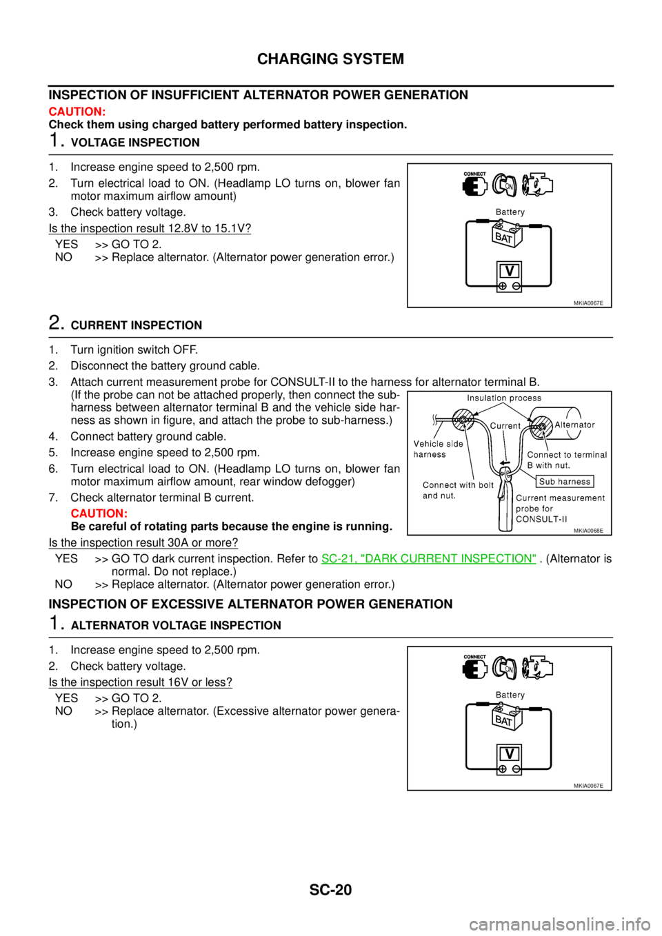
1.VOLTAGE INSPECTION
1. Increase engine speed to 2,500 rpm.
2. Turn electrical load to ON. (Headlamp LO turns on, blower fan
motor maximum airflow amount)
3. Check battery voltage.
Is the inspection result 12.8V to 15.1V?
YES >> GO TO 2.
NO >> Replace alternator. (Alternator power generation error.)
2.CURRENT INSPECTION
1. Turn ignition switch OFF.
2. Disconnect the battery ground cable.
3. Attach current measurement probe for CONSULT-II to the harness for alternator terminal B.
(If the probe can not be attached properly, then connect the sub-
harness between alternator terminal B and the vehicle side har-
ness as shown in figure, and attach the probe to sub-harness.)
4. Connect battery ground cable.
5. Increase engine speed to 2,500 rpm.
6. Turn electrical load to ON. (Headlamp LO turns on, blower fan
motor maximum airflow amount, rear window defogger)
7. Check alternator terminal B current.
CAUTION:
Be careful of rotating parts because the engine is running.
Is the inspection result 30A or more?
YES >> GO TO dark current inspection. Refer toSC-21, "DARK CURRENT INSPECTION". (Alternator is
normal. Do not replace.)
NO >> Replace alternator. (Alternator power generation error.)
INSPECTION OF EXCESSIVE ALTERNATOR POWER GENERATION
1.ALTERNATOR VOLTAGE INSPECTION
1. Increase engine speed to 2,500 rpm.
2. Check battery voltage.
Is the inspection result 16V or less?
YES >> GO TO 2.
NO >> Replace alternator. (Excessive alternator power genera-
tion.)
MKIA0067E
MKIA0068E
MKIA0067E