2005 NISSAN NAVARA ignition
[x] Cancel search: ignitionPage 2692 of 3171
SUNROOF
RF-15
C
D
E
F
G
H
J
K
L
MA
B
RF
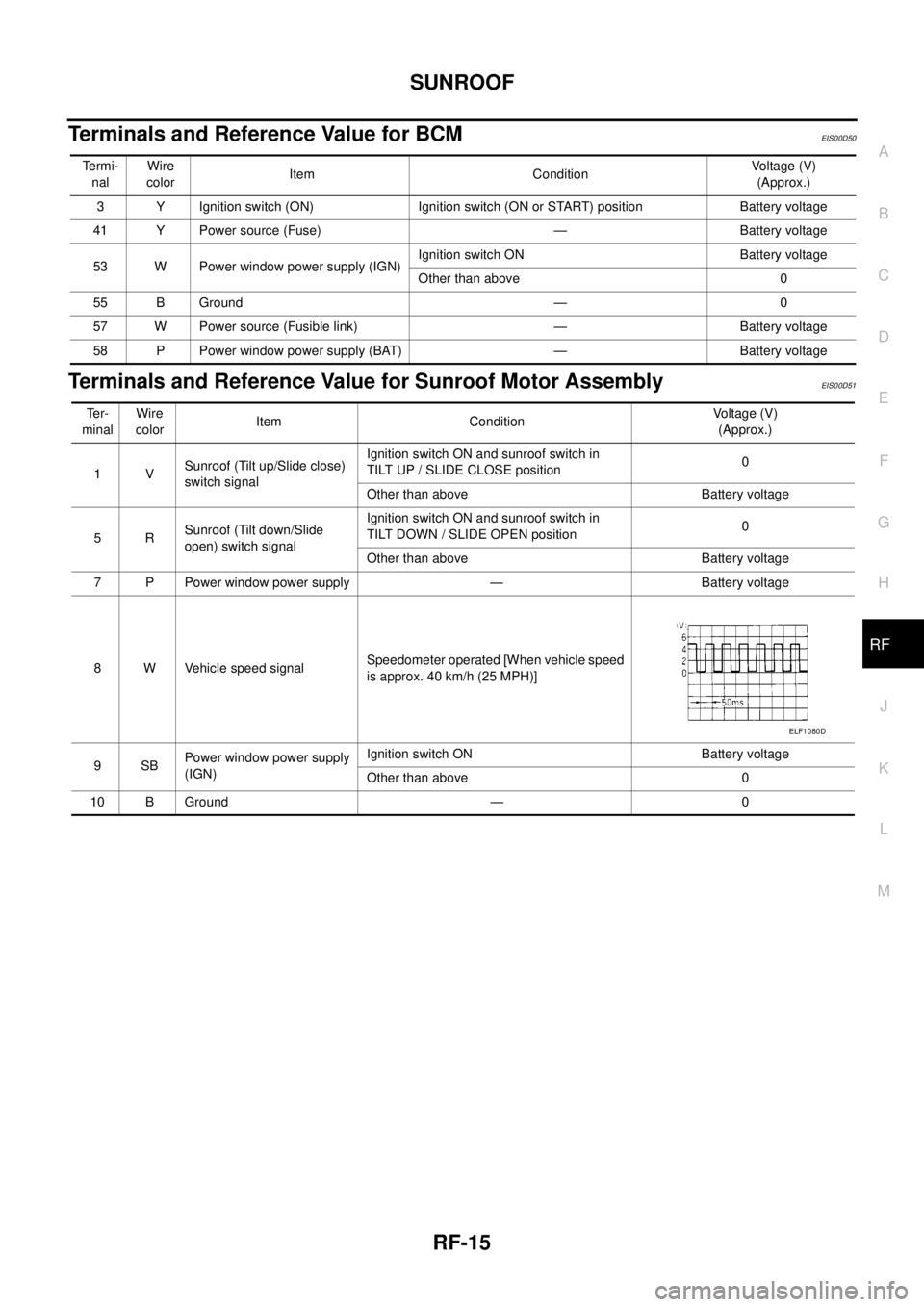
Terminals and Reference Value for BCMEIS00D50
Terminals and Reference Value for Sunroof Motor AssemblyEIS00D51
Te r m i -
nalWire
colorItem ConditionVo l ta g e (V )
(Approx.)
3 Y Ignition switch (ON) Ignition switch (ON or START) position Battery voltage
41 Y Power source (Fuse) — Battery voltage
53 W Power window power supply (IGN)Ignition switch ON Battery voltage
Other than above 0
55 B Ground — 0
57 W Power source (Fusible link) — Battery voltage
58 P Power window power supply (BAT) — Battery voltage
Te r -
minalWire
colorItem ConditionVoltage (V)
(Approx.)
1VSunroof (Tilt up/Slide close)
switch signalIgnition switch ON and sunroof switch in
TILT UP / SLIDE CLOSE position0
Other than above Battery voltage
5RSunroof (Tilt down/Slide
open) switch signalIgnition switch ON and sunroof switch in
TILT DOWN / SLIDE OPEN position0
Other than above Battery voltage
7 P Power window power supply — Battery voltage
8 W Vehicle speed signalSpeedometer operated [When vehicle speed
is approx. 40 km/h (25 MPH)]
9SBPower window power supply
(IGN)Ignition switch ON Battery voltage
Other than above 0
10 B Ground — 0
ELF1080D
Page 2693 of 3171
RF-16
SUNROOF
Work Flow
EIS00D52
1. Check the symptom and customer's requests.
2. Understand the outline of system. Refer toRF-11, "
System Description".
3. According to the trouble diagnosis chart, repair or replace the cause of the malfunction. Refer toRF-16,
"Trouble Diagnosis Symptom Chart".
4. Does sunroof system operate normally? If Yes, GO TO 5. If No, GO TO 3.
5. INSPECTION END.
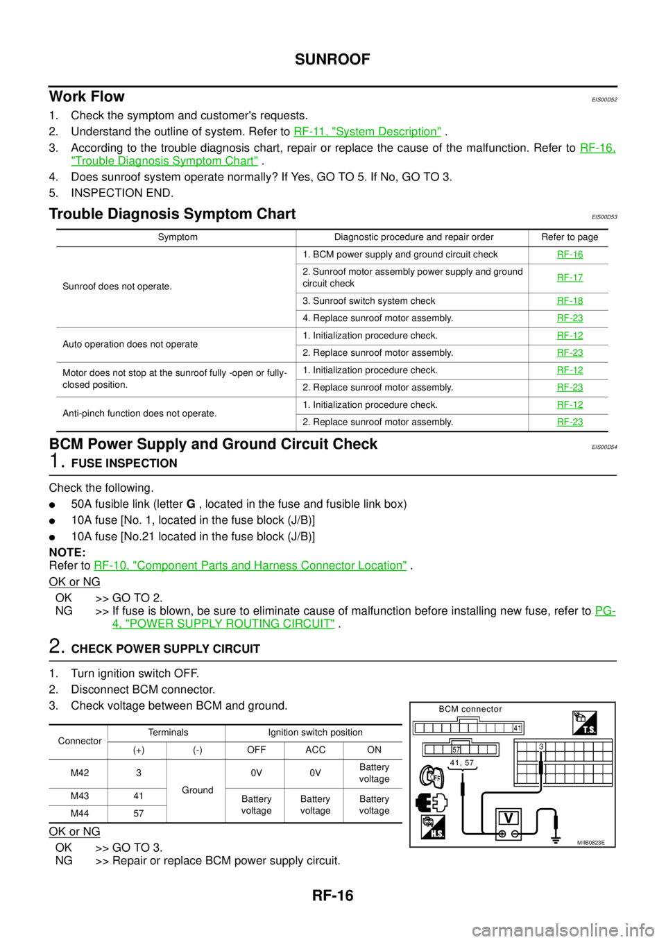
Trouble Diagnosis Symptom ChartEIS00D53
BCM Power Supply and Ground Circuit CheckEIS00D54
1.FUSE INSPECTION
Check the following.
l50A fusible link (letterG, located in the fuse and fusible link box)
l10A fuse [No. 1, located in the fuse block (J/B)]
l10A fuse [No.21 located in the fuse block (J/B)]
NOTE:
Refer toRF-10, "
Component Parts and Harness Connector Location".
OK or NG
OK >> GO TO 2.
NG >> If fuse is blown, be sure to eliminate cause of malfunction before installing new fuse, refer toPG-
4, "POWER SUPPLY ROUTING CIRCUIT".
2.CHECK POWER SUPPLY CIRCUIT
1. Turn ignition switch OFF.
2. Disconnect BCM connector.
3. Check voltage between BCM and ground.
OK or NG
OK >> GO TO 3.
NG >> Repair or replace BCM power supply circuit.
Symptom Diagnostic procedure and repair order Refer to page
Sunroof does not operate.1. BCM power supply and ground circuit checkRF-16
2. Sunroof motor assembly power supply and ground
circuit checkRF-17
3. Sunroof switch system checkRF-18
4. Replace sunroof motor assembly.RF-23
Auto operation does not operate1. Initialization procedure check.RF-122. Replace sunroof motor assembly.RF-23
Motor does not stop at the sunroof fully -open or fully-
closed position.1. Initialization procedure check.RF-12
2. Replace sunroof motor assembly.RF-23
Anti-pinch function does not operate.1. Initialization procedure check.RF-122. Replace sunroof motor assembly.RF-23
ConnectorTerminals Ignition switch position
(+) (-) OFF ACC ON
M42 3
Ground0V 0VBattery
voltage
M43 41
Battery
voltageBattery
voltageBattery
voltage
M44 57
MIIB0823E
Page 2694 of 3171
SUNROOF
RF-17
C
D
E
F
G
H
J
K
L
MA
B
RF
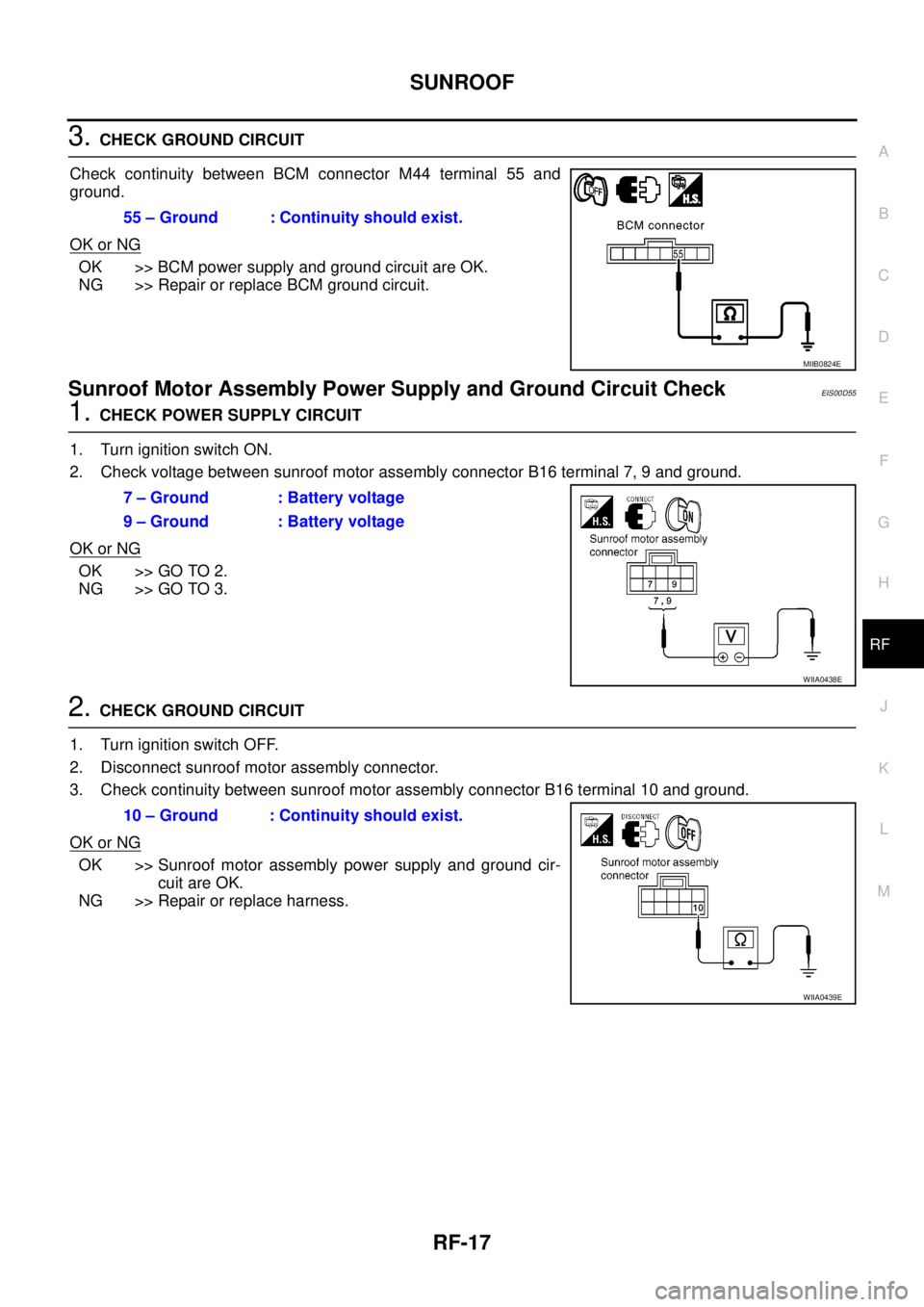
3.CHECK GROUND CIRCUIT
Check continuity between BCM connector M44 terminal 55 and
ground.
OK or NG
OK >> BCM power supply and ground circuit are OK.
NG >> Repair or replace BCM ground circuit.
Sunroof Motor Assembly Power Supply and Ground Circuit CheckEIS00D55
1.CHECK POWER SUPPLY CIRCUIT
1. Turn ignition switch ON.
2. Check voltage between sunroof motor assembly connector B16 terminal 7, 9 and ground.
OK or NG
OK >> GO TO 2.
NG >> GO TO 3.
2.CHECK GROUND CIRCUIT
1. Turn ignition switch OFF.
2. Disconnect sunroof motor assembly connector.
3. Check continuity between sunroof motor assembly connector B16 terminal 10 and ground.
OK or NG
OK >> Sunroof motor assembly power supply and ground cir-
cuit are OK.
NG >> Repair or replace harness.55 – Ground : Continuity should exist.
MIIB0824E
7 – Ground : Battery voltage
9 – Ground : Battery voltage
WIIA0438E
10 – Ground : Continuity should exist.
WIIA0439E
Page 2695 of 3171
RF-18
SUNROOF
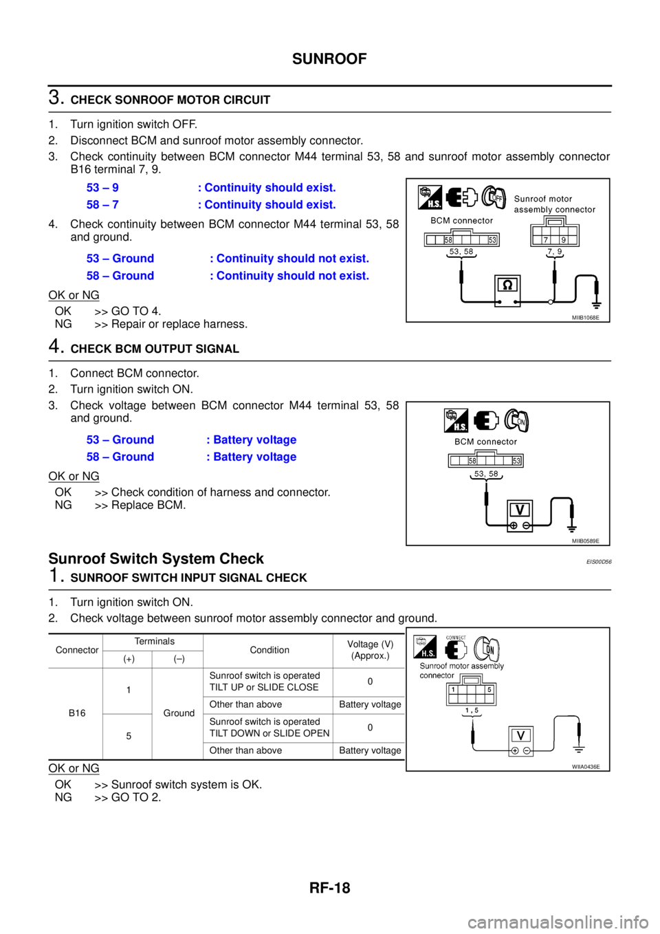
3.CHECK SONROOF MOTOR CIRCUIT
1. Turn ignition switch OFF.
2. Disconnect BCM and sunroof motor assembly connector.
3. Check continuity between BCM connector M44 terminal 53, 58 and sunroof motor assembly connector
B16 terminal 7, 9.
4. Check continuity between BCM connector M44 terminal 53, 58
and ground.
OK or NG
OK >> GO TO 4.
NG >> Repair or replace harness.
4.CHECK BCM OUTPUT SIGNAL
1. Connect BCM connector.
2. Turn ignition switch ON.
3. Check voltage between BCM connector M44 terminal 53, 58
and ground.
OK or NG
OK >> Check condition of harness and connector.
NG >> Replace BCM.
Sunroof Switch System CheckEIS00D56
1.SUNROOF SWITCH INPUT SIGNAL CHECK
1. Turn ignition switch ON.
2. Check voltage between sunroof motor assembly connector and ground.
OK or NG
OK >> Sunroof switch system is OK.
NG >> GO TO 2.53 – 9 : Continuity should exist.
58 – 7 : Continuity should exist.
53 – Ground : Continuity should not exist.
58 – Ground : Continuity should not exist.
MIIB1068E
53 – Ground : Battery voltage
58 – Ground : Battery voltage
MIIB0589E
ConnectorTerminals
ConditionVoltag e (V)
(Approx.)
(+) (–)
B161
GroundSunroof switch is operated
TILT UP or SLIDE CLOSE0
Other than above Battery voltage
5Sunroof switch is operated
TILT DOWN or SLIDE OPEN0
Other than above Battery voltage
WIIA0436E
Page 2696 of 3171
SUNROOF
RF-19
C
D
E
F
G
H
J
K
L
MA
B
RF
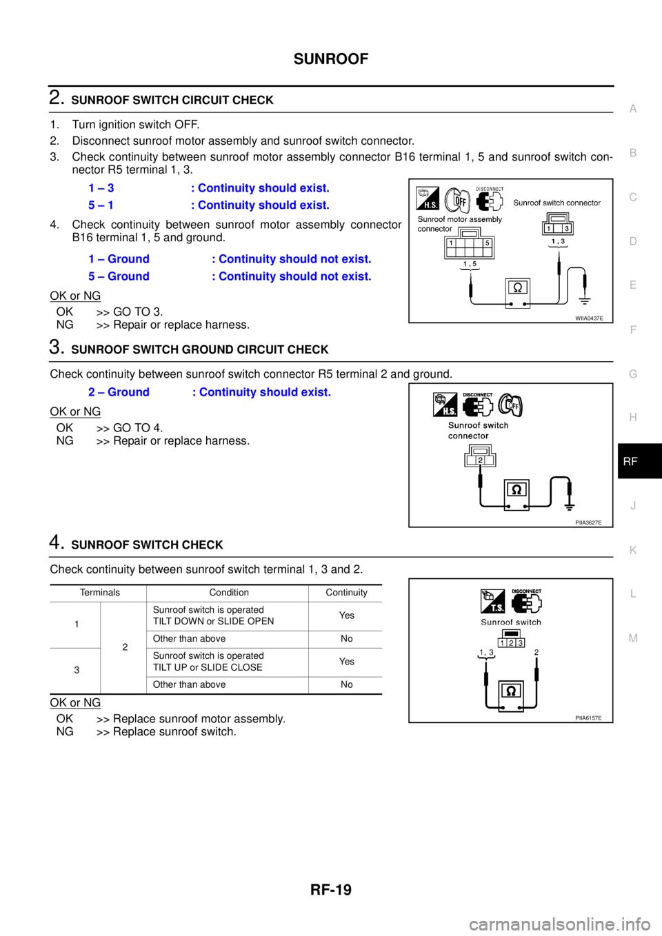
2.SUNROOF SWITCH CIRCUIT CHECK
1. Turn ignition switch OFF.
2. Disconnect sunroof motor assembly and sunroof switch connector.
3. Check continuity between sunroof motor assembly connector B16 terminal 1, 5 and sunroof switch con-
nector R5 terminal 1, 3.
4. Check continuity between sunroof motor assembly connector
B16 terminal 1, 5 and ground.
OK or NG
OK >> GO TO 3.
NG >> Repair or replace harness.
3.SUNROOF SWITCH GROUND CIRCUIT CHECK
Check continuity between sunroof switch connector R5 terminal 2 and ground.
OK or NG
OK >> GO TO 4.
NG >> Repair or replace harness.
4.SUNROOF SWITCH CHECK
Check continuity between sunroof switch terminal 1, 3 and 2.
OK or NG
OK >> Replace sunroof motor assembly.
NG >> Replace sunroof switch.1 – 3 : Continuity should exist.
5 – 1 : Continuity should exist.
1 – Ground : Continuity should not exist.
5 – Ground : Continuity should not exist.
WIIA0437E
2 – Ground : Continuity should exist.
PIIA3627E
Terminals Condition Continuity
1
2Sunroof switch is operated
TILT DOWN or SLIDE OPENYe s
Other than above No
3Sunroof switch is operated
TILT UP or SLIDE CLOSEYe s
Other than above No
PIIA6157E
Page 2737 of 3171
![NISSAN NAVARA 2005 Repair Workshop Manual RFD-34
[WITH ELECTRONIC LOCKING DIFFERENTIAL]
PRECAUTIONS
METHOD FOR ADJUSTMENT
1. Perform erase self-diagnosis with differential lock control unit. Refer toRFD-52, "How to Erase Self-diag-
nostic Res NISSAN NAVARA 2005 Repair Workshop Manual RFD-34
[WITH ELECTRONIC LOCKING DIFFERENTIAL]
PRECAUTIONS
METHOD FOR ADJUSTMENT
1. Perform erase self-diagnosis with differential lock control unit. Refer toRFD-52, "How to Erase Self-diag-
nostic Res](/manual-img/5/57362/w960_57362-2736.png)
RFD-34
[WITH ELECTRONIC LOCKING DIFFERENTIAL]
PRECAUTIONS
METHOD FOR ADJUSTMENT
1. Perform erase self-diagnosis with differential lock control unit. Refer toRFD-52, "How to Erase Self-diag-
nostic Results".
2. Check differential lock control unit input/output signal. Refer toRFD-48, "
Differential Lock Control Unit
Input/Output Signal Reference Values".
3. Check DIFF LOCK indicator lamp. Refer toRFD-33, "
CHECK DIFF LOCK INDICATOR LAMP".
lIf DIFF LOCK indicator lamp is not proper according to the above patterns.
Install new differential lock control unit or check for mechanical malfunction of rear final drive assembly
and retry the above (DIFF LOCK indicator lamp) check.
(If differential lock control unit or rear final drive assembly is replaced from another vehicle, the new dif-
ferential control unit must be replaced first.)
PrecautionsEDS003AH
lBefore connecting or disconnecting differential lock control
unit harness connector, turn ignition switch “OFF” and dis-
connect the battery cables. Because battery voltage is
applied to differential lock control unit even if ignition
switch is turned “OFF”.
lWhen connecting or disconnecting pin connectors into or
from differential lock control unit, take care not to damage
pin terminals (bend or break).
When connecting pin connectors make sure that there are
not any bends or breaks on differential lock control unit pin
terminal.
lBefore replacing differential lock control unit, perform dif-
ferential lock control unit input/output signal inspection
and make sure whether differential lock control unit func-
tions properly or not. Refer toRFD-48, "
Differential Lock
Control Unit Input/Output Signal Reference Values".
SEF289H
SEF291H
SDIA1848E
Page 2745 of 3171
![NISSAN NAVARA 2005 Repair Workshop Manual RFD-42
[WITH ELECTRONIC LOCKING DIFFERENTIAL]
DIFFERENTIAL LOCK SYSTEM
Differential Lock Operation
EDS003AQ
1. Differential lock solenoid operates pressure plate.
2. Pressure plate presses cam ring.
3 NISSAN NAVARA 2005 Repair Workshop Manual RFD-42
[WITH ELECTRONIC LOCKING DIFFERENTIAL]
DIFFERENTIAL LOCK SYSTEM
Differential Lock Operation
EDS003AQ
1. Differential lock solenoid operates pressure plate.
2. Pressure plate presses cam ring.
3](/manual-img/5/57362/w960_57362-2744.png)
RFD-42
[WITH ELECTRONIC LOCKING DIFFERENTIAL]
DIFFERENTIAL LOCK SYSTEM
Differential Lock Operation
EDS003AQ
1. Differential lock solenoid operates pressure plate.
2. Pressure plate presses cam ring.
3. Engage cam ring and side gear, and then differential is locked.
System DescriptionEDS003AR
DIFFERENTIAL LOCK SOLENOID
It is operated by signal from differential lock control unit, and it operates pressure plate so as to switch lock/
unlock.
DIFFERENTIAL LOCK POSITION SWITCH
It detects that differential is in lock or unlock by pressure plate position, and sends it to differential lock control
unit.
DIFFERENTIAL LOCK CONTROL UNIT
lDifferential lock control unit controls differential lock solenoid by input signals of each sensor and each
switch.
lAs a fail-safe function, differential lock disengages, if malfunction is detected in differential lock system.
lSelf-diagnosis can be done with CONSULT-II.
DIFFERENTIAL LOCK MODE SWITCH
Able to select differential lock and unlock.
DIFF LOCK INDICATOR LAMP
The following is the indications of indicator lamp.
NOTE:
Differential lock standby condition is the condition that differential lock mode switch is ON and differential is unlocked.
SDIA2498E
Condition DIFF LOCK indicator lamp
Differential lock/unlock ON/OFF
Differential lock standby condition Flashing: 1 time/2 seconds
Differential lock system malfunction OFF (Even if differential lock mode switch is turned ON)
Lamp checkTurns ON when ignition switch is turned ON.
Turns OFF after engine start.
Page 2751 of 3171
![NISSAN NAVARA 2005 Repair Workshop Manual RFD-48
[WITH ELECTRONIC LOCKING DIFFERENTIAL]
TROUBLE DIAGNOSIS
Trouble Diagnosis Chart for Symptoms
EDS003AY
If DIFF LOCK indicator lamp does not turn ON after engine start, perform self-diagnosis. R NISSAN NAVARA 2005 Repair Workshop Manual RFD-48
[WITH ELECTRONIC LOCKING DIFFERENTIAL]
TROUBLE DIAGNOSIS
Trouble Diagnosis Chart for Symptoms
EDS003AY
If DIFF LOCK indicator lamp does not turn ON after engine start, perform self-diagnosis. R](/manual-img/5/57362/w960_57362-2750.png)
RFD-48
[WITH ELECTRONIC LOCKING DIFFERENTIAL]
TROUBLE DIAGNOSIS
Trouble Diagnosis Chart for Symptoms
EDS003AY
If DIFF LOCK indicator lamp does not turn ON after engine start, perform self-diagnosis. Refer toRFD-51, "SELF-DIAG RESULTSMODE".
Differential Lock Control Unit Input/Output Signal Reference ValuesEDS003AZ
DIFFERENTIAL LOCK CONTROL UNIT INSPECTION TABLE
Specifications with CONSULT-II
Symptom Condition Check itemReference
page
DIFF LOCK indicator lamp does not turn ON.
(DIFF LOCK indicator lamp check)Ignition switch: ONCAN communication line
RFD-70
Power supply and ground for differential
lock control unit
Combination meter
DIFF LOCK indicator lamp does not change.
lEngine running
lDifferential lock mode
switch: ONCombination meter
RFD-73Differential lock mode switch
CAN communication line
DIFF LOCK indicator lamp sometimes flashes.
lEngine running
lDifferential lock mode
switch: ONCombination meter
RFD-74Differential lock mode switch
Differential lock position switch
Differential inner parts
Monitor item [Unit] Content Condition Display value
BATTERY VOLT [V]Power supply voltage for
differential lock control unitIgnition switch: ON Battery voltage
4WD MODE [2H/4H/
4Lo]Condition of 4WD shift
switch4WD shift switch
(Engine running)2WD 2H
4H 4H
4LO 4Lo
VHCL S/SEN-R [km/h]
or [mph]Wheel speed
(Rear wheel right)Vehicle stopped 0 km/h (0 mph)
Vehicle running
CAUTION:
Check air pressure of tire under standard condition.Approximately
equal to the indi-
cation on speed-
ometer (Inside of
±10%)
VHCL S/SEN-L [km/h] or
[mph]Wheel speed
(Rear wheel left)Vehicle stopped 0 km/h (0 mph)
Vehicle running
CAUTION:
Check air pressure of tire under standard condition.Approximately
equal to the indi-
cation on speed-
ometer (Inside of
±10%)
VHCL S/SEN-RL [km/h]
or [mph]Wheel speed
(Average value of rear
wheel right and left)Vehicle stopped 0 km/h (0 mph)
Vehicle running
CAUTION:
Check air pressure of tire under standard condition.Approximately
equal to the indi-
cation on speed-
ometer (Inside of
±10%)
D-LOCK SW SIG [ON/
OFF]Condition of differential
lock mode switchDifferential lock mode switch: ON ON
Differential lock mode switch: OFF OFF
D-LOCK SIG [ON/OFF]Control status of differen-
tial lock
lVehicle stopped
lEngine running
l4WD shift switch: 4LODifferential lock mode
switch: ONON
Differential lock mode
switch: OFFOFF