Page 2448 of 3171
TROUBLE DIAGNOSIS
MTC-61
C
D
E
F
G
H
I
K
L
MA
B
MTC
5.CHECK PBR REFERENCE VOLTAGE CIRCUIT BETWEEN MODE DOOR AND FRONT AIR CONTROL
1. Turn ignition switch OFF.
2. Disconnect the front air control connector.
3. Check continuity between mode door motor harness connector
M46 terminal 3 and front air control harness connector M98 ter-
minal 23.
OK or NG
OK >> Replace front air control. Refer toMTC-98, "CONTROL
UNIT".
NG >> Repair or replace harness as necessary.
6.CHECK PBR GROUND REFERENCE CIRCUIT
1. Turn ignition switch OFF.
2. Disconnect the front air control connector.
3. Check continuity between mode door motor harness connector
M46 terminal 2 and front air control harness connector M98 ter-
minal 26.
OK or NG
OK >> GO TO 7.
NG >> Repair or replace harness as necessary.3 - 23 : Continuity should exist.
MJIB0234E
2 - 26 : Continuity should exist.
MJIB0235E
Page 2449 of 3171
MTC-62
TROUBLE DIAGNOSIS
7.CHECK PBR FEEDBACK SIGNAL
1. Reconnect the front air control connector and mode door motor
connector.
2. Turn ignition switch ON.
3. Check voltage between front air control harness connector M98
terminal 21 and ground.
4. Press mode switch through all modes.
OK or NG
OK >> Replace front air control. Refer toMTC-98, "CONTROL
UNIT".
NG >> GO TO 8.
8.CHECK PBR FEEDBACK CIRCUIT
1. Turn ignition switch OFF.
2. Disconnect the mode door motor connector and front air control
harness connector.
3. Check continuity between mode door motor harness connector
M46 terminal 4 and front air control harness connector M98 ter-
minal 21.
OK or NG
OK >> Replace mode door motor. Refer toMTC-110, "MODE
DOOR MOTOR".
NG >> Repair or replace harness as necessary.21 - Ground : Approx. 0 - 5V
WJIA1088E
4 - 21 : Continuity should exist.
WJIA1089E
Page 2452 of 3171
TROUBLE DIAGNOSIS
MTC-65
C
D
E
F
G
H
I
K
L
MA
B
MTC
3.CHECK POWER SUPPLY CIRCUITS FOR AIR MIX DOOR MOTOR (FRONT)
1. Turn ignition switch OFF.
2. Disconnect front air control connector and air mix door motor
(Front) connector.
3. Check continuity between front air control harness connector
M98 terminal 2 and 3 and air mix door motor (Front) connector
M99 terminal 6 and 5.
OK or NG
OK >> Replace air mix door motor (Front). Refer toM T C - 111 ,
"AIR MIX DOOR MOTOR".
NG >> Repair or replace harness as necessary.
4.CHECK PBR REFERENCE SIGNAL VOLTAGE
1. Turn ignition switch OFF.
2. Disconnect the air mix door motor (Front) connector.
3. Turn ignition switch ON.
4. Check voltage between air mix door motor (Front) harness con-
nector M99 terminal 1 and ground.
OK or NG
OK >> GO TO 6.
NG >> GO TO 5.2 - 6 : Continuity should exist.
3 - 5 : Continuity should exist.
MJIB0094E
1 - Ground : Approx. 5V
MJIB0095E
Page 2453 of 3171
MTC-66
TROUBLE DIAGNOSIS
5.CHECK PBR REFERENCE VOLTAGE CIRCUIT BETWEEN AIR MIX DOOR MOTOR (FRONT) AND
FRONT AIR CONTROL
1. Turn ignition switch OFF.
2. Disconnect the front air control connector.
3. Check continuity between air mix door motor (Front) harness
connector M99 terminal 1 and front air control harness connec-
tor M98 terminal 23.
OK or NG
OK >> Replace front air control. Refer toMTC-98, "CONTROL
UNIT".
NG >> Repair or replace harness as necessary.
6.CHECK PBR GROUND REFERENCE CIRCUIT
1. Turn ignition switch OFF.
2. Disconnect the front air control connector.
3. Check continuity between air mix door motor (Front) harness
connector M99 terminal 3 and front air control harness connec-
tor M98 terminal 26.
OK or NG
OK >> GO TO 7.
NG >> Repair or replace harness as necessary.1 - 23 : Continuity should exist.
MJIB0096E
3 - 26 : Continuity should exist.
MJIB0237E
Page 2454 of 3171
TROUBLE DIAGNOSIS
MTC-67
C
D
E
F
G
H
I
K
L
MA
B
MTC
7.CHECK PBR FEEDBACK SIGNAL
1. Turn ignition switch OFF.
2. Reconnect the front air control connector and air mix door motor
(Front) connector.
3. Check voltage between front air control harness connector M98
terminal 22 and ground.
4. Rotate Front temperature dial through complete range.
OK or NG
OK >> Replace front air control. Refer toMTC-98, "CONTROL
UNIT".
NG >> GO TO 8.
8.CHECK PBR FEEDBACK CIRCUIT
1. Turn ignition switch OFF.
2. Disconnect the air mix door motor (Front) connector and front air
control connector.
3. Check continuity between air mix door motor (Front) harness
connector M99 terminal 2 and front air control harness connec-
tor M98 terminal 22.
OK or NG
OK >> Replace air mix door motor (Front). Refer toM T C - 111 ,
"AIR MIX DOOR MOTOR".
NG >> Repair or replace harness as necessary.22 - Ground : Approx. 0V - 5V
MJIB0098E
2 - 22 Continuity should exist.
MJIB0099E
Page 2457 of 3171
MTC-70
TROUBLE DIAGNOSIS
3.CHECK POWER SUPPLY CIRCUIT FOR INTAKE DOOR MOTOR
1. Turn ignition switch OFF.
2. Disconnect front air control connector and intake door motor
connector.
3. Check continuity between front air control harness connector
M98 terminal 5 and intake door motor connector M86 terminal 6
and between front air control harness connector M98 terminal 4
and intake door motor connector M86 terminal 1.
OK or NG
OK >> Replace intake door motor. Refer toMTC-109, "INTAKE
DOOR MOTOR".
NG >> Repair or replace harness as necessary.5 - 6 Continuity should exist.
4 - 1 Continuity should exist.
MJIB0239E
Page 2461 of 3171

MTC-74
TROUBLE DIAGNOSIS
4.CHECK BLOWER MOTOR RELAY
Refer toMTC-77, "
Blower Motor Relay".
OK or NG
OK >> GO TO 5.
NG >> Replace blower motor relay.
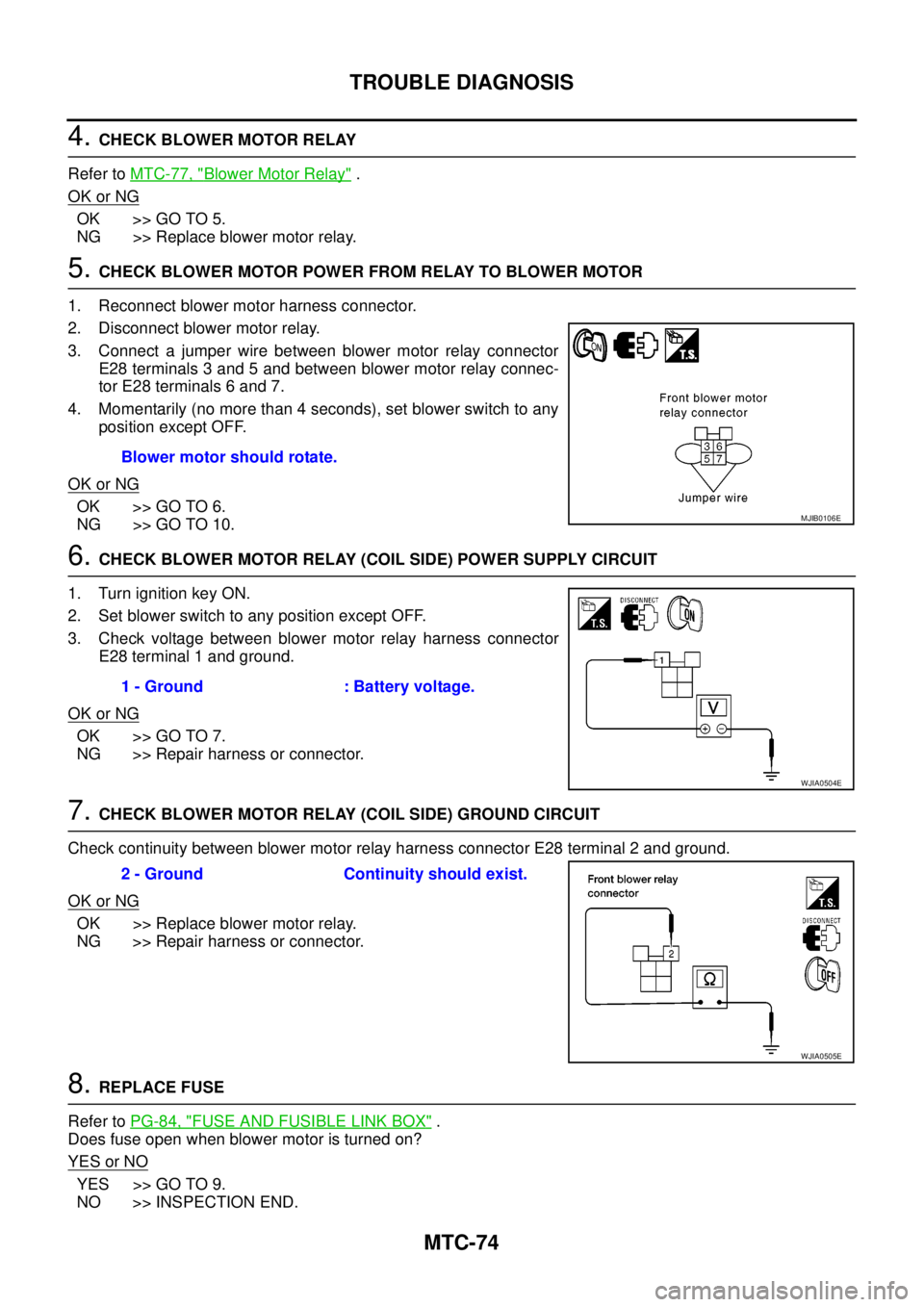
5.CHECK BLOWER MOTOR POWER FROM RELAY TO BLOWER MOTOR
1. Reconnect blower motor harness connector.
2. Disconnect blower motor relay.
3. Connect a jumper wire between blower motor relay connector
E28 terminals 3 and 5 and between blower motor relay connec-
tor E28 terminals 6 and 7.
4. Momentarily (no more than 4 seconds), set blower switch to any
position except OFF.
OK or NG
OK >> GO TO 6.
NG >> GO TO 10.
6.CHECK BLOWER MOTOR RELAY (COIL SIDE) POWER SUPPLY CIRCUIT
1. Turn ignition key ON.
2. Set blower switch to any position except OFF.
3. Check voltage between blower motor relay harness connector
E28 terminal 1 and ground.
OK or NG
OK >> GO TO 7.
NG >> Repair harness or connector.
7.CHECK BLOWER MOTOR RELAY (COIL SIDE) GROUND CIRCUIT
Check continuity between blower motor relay harness connector E28 terminal 2 and ground.
OK or NG
OK >> Replace blower motor relay.
NG >> Repair harness or connector.
8.REPLACE FUSE
Refer toPG-84, "
FUSE AND FUSIBLE LINK BOX".
Does fuse open when blower motor is turned on?
YESorNO
YES >> GO TO 9.
NO >> INSPECTION END.Blower motor should rotate.
MJIB0106E
1 - Ground : Battery voltage.
WJIA0504E
2 - Ground Continuity should exist.
WJIA0505E
Page 2468 of 3171

TROUBLE DIAGNOSIS
MTC-81
C
D
E
F
G
H
I
K
L
MA
B
MTC
2.PERFORM AUTO ACTIVE TEST
Refer toPG-19, "
Auto Active Test".
Does magnet clutch operate?
YES or NO
YES >>lWITH CONSULT-II
GO TO 5.
lWITHOUT CONSULT-II
GO TO 6.
NO >> Check 10A fuse (No. 42, located in IPDM E/R), and GO TO 3.
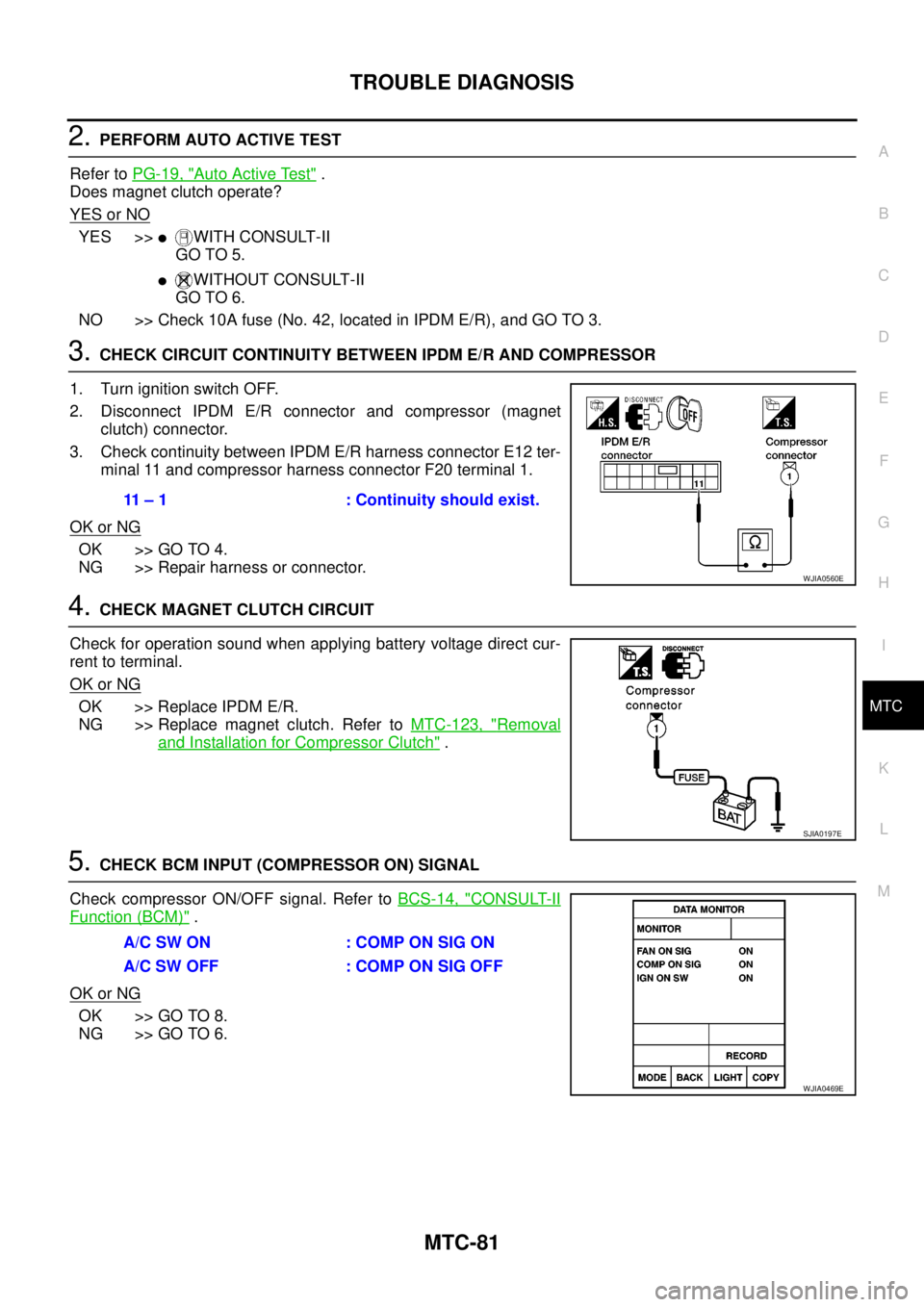
3.CHECK CIRCUIT CONTINUITY BETWEEN IPDM E/R AND COMPRESSOR
1. Turn ignition switch OFF.
2. Disconnect IPDM E/R connector and compressor (magnet
clutch) connector.
3. Check continuity between IPDM E/R harness connector E12 ter-
minal 11 and compressor harness connector F20 terminal 1.
OK or NG
OK >> GO TO 4.
NG >> Repair harness or connector.
4.CHECK MAGNET CLUTCH CIRCUIT
Check for operation sound when applying battery voltage direct cur-
rent to terminal.
OK or NG
OK >> Replace IPDM E/R.
NG >> Replace magnet clutch. Refer toMTC-123, "
Removal
and Installation for Compressor Clutch".
5.CHECK BCM INPUT (COMPRESSOR ON) SIGNAL
Check compressor ON/OFF signal. Refer toBCS-14, "
CONSULT-II
Function (BCM)".
OK or NG
OK >> GO TO 8.
NG >> GO TO 6.
11 – 1 : Continuity should exist.
WJIA0560E
SJIA0197E
A/C SW ON : COMP ON SIG ON
A/CSWOFF :COMPONSIGOFF
WJIA0469E