Page 2244 of 3171

INTERIOR ROOM LAMP
LT-161
C
D
E
F
G
H
I
J
L
MA
B
LT
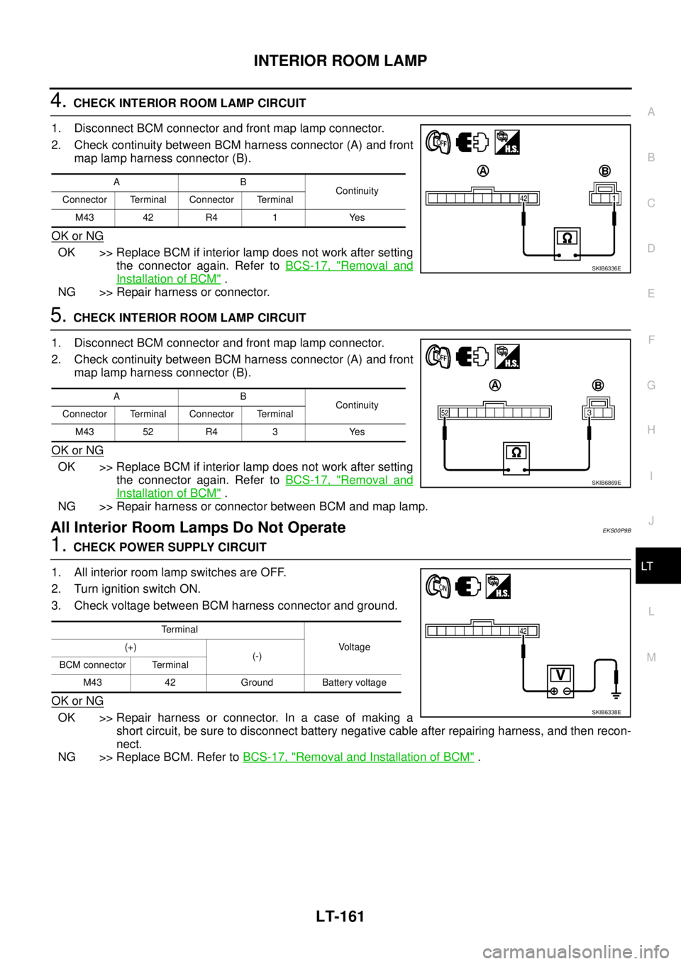
4.CHECK INTERIOR ROOM LAMP CIRCUIT
1. Disconnect BCM connector and front map lamp connector.
2. Check continuity between BCM harness connector (A) and front
map lamp harness connector (B).
OK or NG
OK >> Replace BCM if interior lamp does not work after setting
the connector again. Refer toBCS-17, "
Removal and
Installation of BCM".
NG >> Repair harness or connector.
5.CHECK INTERIOR ROOM LAMP CIRCUIT
1. Disconnect BCM connector and front map lamp connector.
2. Check continuity between BCM harness connector (A) and front
map lamp harness connector (B).
OK or NG
OK >> Replace BCM if interior lamp does not work after setting
the connector again. Refer toBCS-17, "
Removal and
Installation of BCM".
NG >> Repair harness or connector between BCM and map lamp.
All Interior Room Lamps Do Not OperateEKS00P9B
1.CHECK POWER SUPPLY CIRCUIT
1. All interior room lamp switches are OFF.
2. Turn ignition switch ON.
3. Check voltage between BCM harness connector and ground.
OK or NG
OK >> Repair harness or connector. In a case of making a
short circuit, be sure to disconnect battery negative cable after repairing harness, and then recon-
nect.
NG >> Replace BCM. Refer toBCS-17, "
Removal and Installation of BCM".
AB
Continuity
Connector Terminal Connector Terminal
M43 42 R4 1 Yes
SKIB6336E
AB
Continuity
Connector Terminal Connector Terminal
M43 52 R4 3 Yes
SKIB6869E
Te r m i n a l
Voltage (+)
(-)
BCM connector Terminal
M43 42 Ground Battery voltage
SKIB6338E
Page 2245 of 3171

LT-162
ILLUMINATION
ILLUMINATION
PFP:27545
System DescriptionEKS00P8V
Control of the illumination lamps operation is dependent upon the position of the lighting switch (combination
switch). When the lighting switch is placed in the 1ST position, 2ND position or AUTO position (headlamp is
ON) the BCM (body control module) receives input signal requesting the illumination lamps to illuminate. This
input signal is communicated to the IPDM E/R (intelligent power distribution module engine room) through the
CAN communication. The CPU (central processing unit) of the IPDM E/R controls the tail lamp relay coil. This
relay, when energized, directs power to the illumination lamps, which then illuminate.
Power is supplied at all times
lto ignition relay (located in IPDM E/R) and
lto tail lamp relay (located in IPDM E/R), from battery directly,
lthrough 50A fusible link (letter G, located in fuse and fusible link box)
lto BCM terminal 57,
lthrough 20A fuse (No. 52, located in IPDM E/R) and
lthrough 20A fuse (No. 53, located in IPDM E/R)
lto CPU (located in IPDM E/R),
lthrough 10A fuse [No.19, located in fuse block (J/B)]
lto combination meter terminal 3.
With the ignition switch in the ON or START position, power is supplied
lto ignition relay (located in IPDM E/R),
lthrough 10A fuse [No. 1, located in fuse block (J/B)]
lto BCM terminal 3,
lthrough 10A fuse [No. 14, located in fuse block (J/B)]
lto combination meter 16.
Ground is supplied
lto BCM terminal 55 and
lto combination meter terminal 23
lthrough grounds M21, M80 and M83,
lto IPDM E/R terminals 38 and 59
lthrough grounds E21, E41 and E61.
ILLUMINATION OPERATION BY LIGHTING SWITCH
With the lighting switch in the 1ST position, 2ND position or AUTO position (headlamp is ON), the BCM
receives input signal requesting the illumination lamps to illuminate. This input signal is communicated to the
IPDM E/R through the CAN communication. The CPU of the IPDM E/R controls the tail lamp relay coil, which,
when energized, directs power
lthrough 10A fuse (No. 37, located in IPDM E/R)
lthrough IPDM E/R terminal 57
lto hazard switch (illumination) terminal 3
lto 4WD shift switch (illumination) terminal 7 (with 4-wheel drive)
lto front air control (illumination) terminal 8
lto audio unit (illumination) terminal 2 (1CD player)
lto audio unit (illumination) terminal 8 (6CD player)
lto AV switch (illumination) terminal 3 (with NAVI)
lto audio unit (illumination) terminal 29 (with NAVI)
lto glove box lamp terminal 1
lto A/T device (illumination) terminal 3 (with A/T)
lto heat up switch (illumination) terminal 5
lto DIFF LOCK switch (illumination) terminal 4 (with DIFF LOCK)
lto heated seat switch (driver side) (illumination) terminal 5 (with heated seats)
lto heated seat switch (passenger side) (illumination) terminal 5 (with heated seats)
Page 2420 of 3171
TROUBLE DIAGNOSIS
MTC-33
C
D
E
F
G
H
I
K
L
MA
B
MTC
TROUBLE DIAGNOSISPFP:00004
CONSULT-IIEJS005G4
CONSULT-II can display each diagnostic item using the diagnostic test modes shown following.
CONSULT-II BASIC OPERATION
CAUTION:
If CONSULT-II is used with no connection of CONSULT-II CONVERTER, malfunctions might be
detected in self-diagnosis depending on control unit which carry out CAN communication.
1. With the ignition switch OFF, connect CONSULT-II and “CON-
SULT-II converter” to the data link connector, and turn the igni-
tion switch ON.
2. Touch “START (NISSAN BASED VHCL)”.
3. Touch “BCM” on “SELECT SYSTEM” screen. If “BCM” is not
indicated, go toGI-50, "
CONSULT-II Data Link Connector (DLC)
Circuit".
System part Check item, diagnosis mode Description
BCM Data monitor Displays BCM input data in real time.
BBIA0369E
BCIA0029E
BCIA0030E
Page 2421 of 3171

MTC-34
TROUBLE DIAGNOSIS
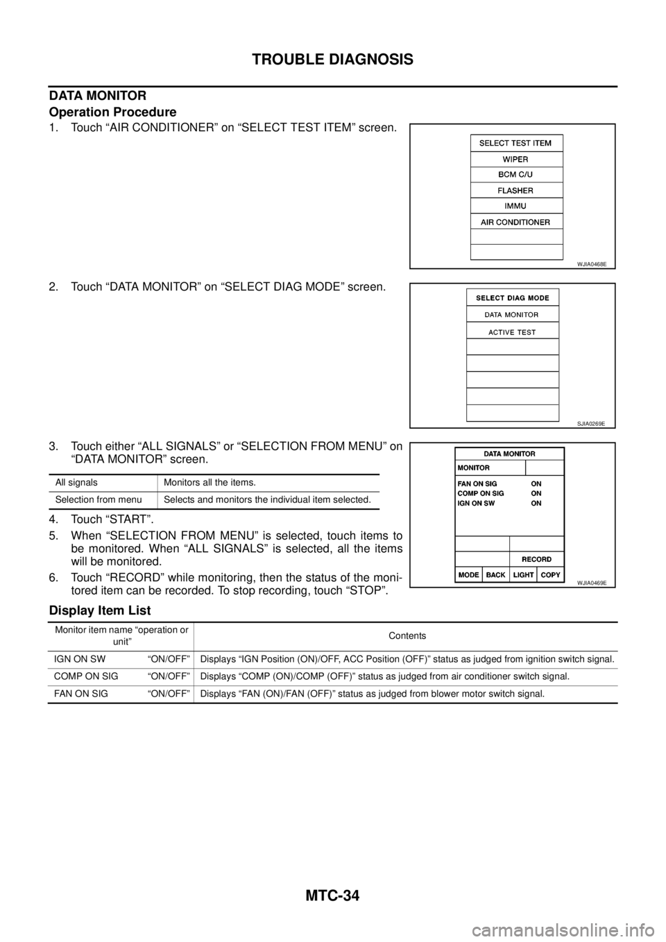
DATA MONITOR
Operation Procedure
1. Touch “AIR CONDITIONER” on “SELECT TEST ITEM” screen.
2. Touch “DATA MONITOR” on “SELECT DIAG MODE” screen.
3. Touch either “ALL SIGNALS” or “SELECTION FROM MENU” on
“DATA MONITOR” screen.
4. Touch “START”.
5. When “SELECTION FROM MENU” is selected, touch items to
be monitored. When “ALL SIGNALS” is selected, all the items
will be monitored.
6. Touch “RECORD” while monitoring, then the status of the moni-
tored item can be recorded. To stop recording, touch “STOP”.
Display Item List
WJIA0468E
SJIA0269E
All signals Monitors all the items.
Selection from menu Selects and monitors the individual item selected.
WJIA0469E
Monitor item name “operation or
unit”Contents
IGN ON SW “ON/OFF” Displays “IGN Position (ON)/OFF, ACC Position (OFF)” status as judged from ignition switch signal.
COMP ON SIG “ON/OFF” Displays “COMP (ON)/COMP (OFF)” status as judged from air conditioner switch signal.
FAN ON SIG “ON/OFF” Displays “FAN (ON)/FAN (OFF)” status as judged from blower motor switch signal.
Page 2436 of 3171

TROUBLE DIAGNOSIS
MTC-49
C
D
E
F
G
H
I
K
L
MA
B
MTC
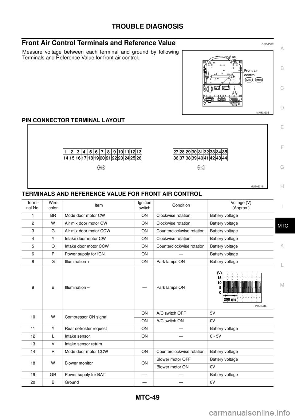
Front Air Control Terminals and Reference ValueEJS005G9
Measure voltage between each terminal and ground by following
Terminals and Reference Value for front air control.
PIN CONNECTOR TERMINAL LAYOUT
TERMINALS AND REFERENCE VALUE FOR FRONT AIR CONTROL
MJIB0320E
MJIB0321E
Te r m i -
nal No.Wire
colorItemIgnition
switchConditionVoltage (V)
(Approx.)
1 BR Mode door motor CW ON Clockwise rotation Battery voltage
2 W Air mix door motor CW ON Clockwise rotation Battery voltage
3 G Air mix door motor CCW ON Counterclockwise rotation Battery voltage
4 Y Intake door motor CW ON Clockwise rotation Battery voltage
5 O Intake door motor CCW ON Counterclockwise rotation Battery voltage
6 P Power supply for IGN ON — Battery voltage
8 G Illumination + ON Park lamps ON Battery voltage
9 B Illumination – — Park lamps ON
10 W Compressor ON signalON A/C switch OFF 5V
ON A/C switch ON 0V
11 Y Rear defroster request ON — Battery voltage
12 L Intake sensor ON — 0 - 5V
13 V Intake sensor return
14 R Mode door motor CCW ON Counterclockwise rotation Battery voltage
18 W Blower monitor ONBlower motor OFF Battery voltage
Blower motor ON 0V
19 GR Power supply for BAT — — Battery voltage
20 B Ground — — 0V
PIIA2344E
Page 2437 of 3171
MTC-50
TROUBLE DIAGNOSIS
21 V Mode door motor feedback ON — 0 - 5V
22 SB Air mix door motor feedback ON — 0 - 5V
23 G Sensor power ON — 5V
25 LG Rear defroster status
26 P Sensor return ON — 0 - 5V
36 PPTC heater relay 1
(LHD models)ONRelay ON Battery voltage
Relay OFF 0V
37 LGPTC heater relay 2
(LHD models)ONRelay ON Battery voltage
Relay OFF 0V
38 BRPTC heater relay 3
(LHD models)ONRelay ON Battery voltage
Relay OFF 0V
39 YSeat heater
(LHD models)ONSeat heater ON Battery voltage
Seat heater OFF 0V
40 RMirror heater
(LHD models)ONMirror heater ON Battery voltage
Mirror heater OFF 0V
41 LCAN-H
(LHD models)ON — 0 - 5V
42 PCAN-L
(LHD models)ON — 0 - 5V Te r m i -
nal No.Wire
colorItemIgnition
switchConditionVoltage (V)
(Approx.)
Page 2444 of 3171

TROUBLE DIAGNOSIS
MTC-57
C
D
E
F
G
H
I
K
L
MA
B
MTC
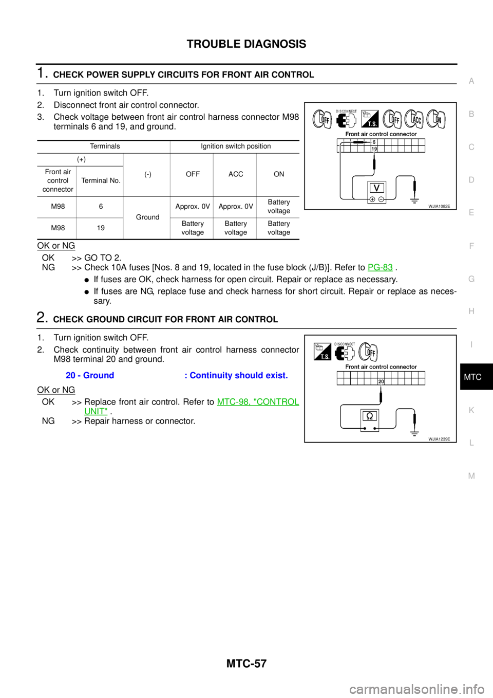
1.CHECK POWER SUPPLY CIRCUITS FOR FRONT AIR CONTROL
1. Turn ignition switch OFF.
2. Disconnect front air control connector.
3. Check voltage between front air control harness connector M98
terminals 6 and 19, and ground.
OK or NG
OK >> GO TO 2.
NG >> Check 10A fuses [Nos. 8 and 19, located in the fuse block (J/B)]. Refer toPG-83
.
lIf fuses are OK, check harness for open circuit. Repair or replace as necessary.
lIf fuses are NG, replace fuse and check harness for short circuit. Repair or replace as neces-
sary.
2.CHECK GROUND CIRCUIT FOR FRONT AIR CONTROL
1. Turn ignition switch OFF.
2. Check continuity between front air control harness connector
M98 terminal 20 and ground.
OK or NG
OK >> Replace front air control. Refer toMTC-98, "CONTROL
UNIT".
NG >> Repair harness or connector.
Terminals Ignition switch position
(+)
(-) OFF ACC ON Front air
control
connectorTerminal No.
M98 6
GroundApprox. 0V Approx. 0VBattery
voltage
M98 19Battery
voltageBattery
voltageBattery
voltage
WJIA1082E
20 - Ground : Continuity should exist.
WJIA1239E
Page 2447 of 3171
MTC-60
TROUBLE DIAGNOSIS
3.CHECK POWER SUPPLY AND GROUND CIRCUITS FOR MODE DOOR MOTOR
1. Turn ignition switch OFF.
2. Disconnect front air control connector and mode door motor
connector.
3. Check continuity between front air control harness connector
M98 terminal 1 and mode door motor connector M46 terminal 1
and between front air control harness connector M98 terminal
14 and mode door motor connector M46 terminal 6.
OK or NG
OK >> Replace mode door motor.
NG >> Repair or replace harness as necessary.
4.CHECK PBR REFERENCE SIGNAL VOLTAGE
1. Turn ignition switch OFF.
2. Disconnect the mode door motor connector.
3. Turn ignition switch ON.
4. Check voltage between mode door motor harness connector
M46 terminal 3 and ground.
OK or NG
OK >> GO TO 6.
NG >> GO TO 5.1 - 1 : Continuity should exist.
14 - 6 : Continuity should exist.
MJIB0232E
3 - Ground : Approx. 5V
MJIB0233E