Page 2469 of 3171

MTC-82
TROUBLE DIAGNOSIS
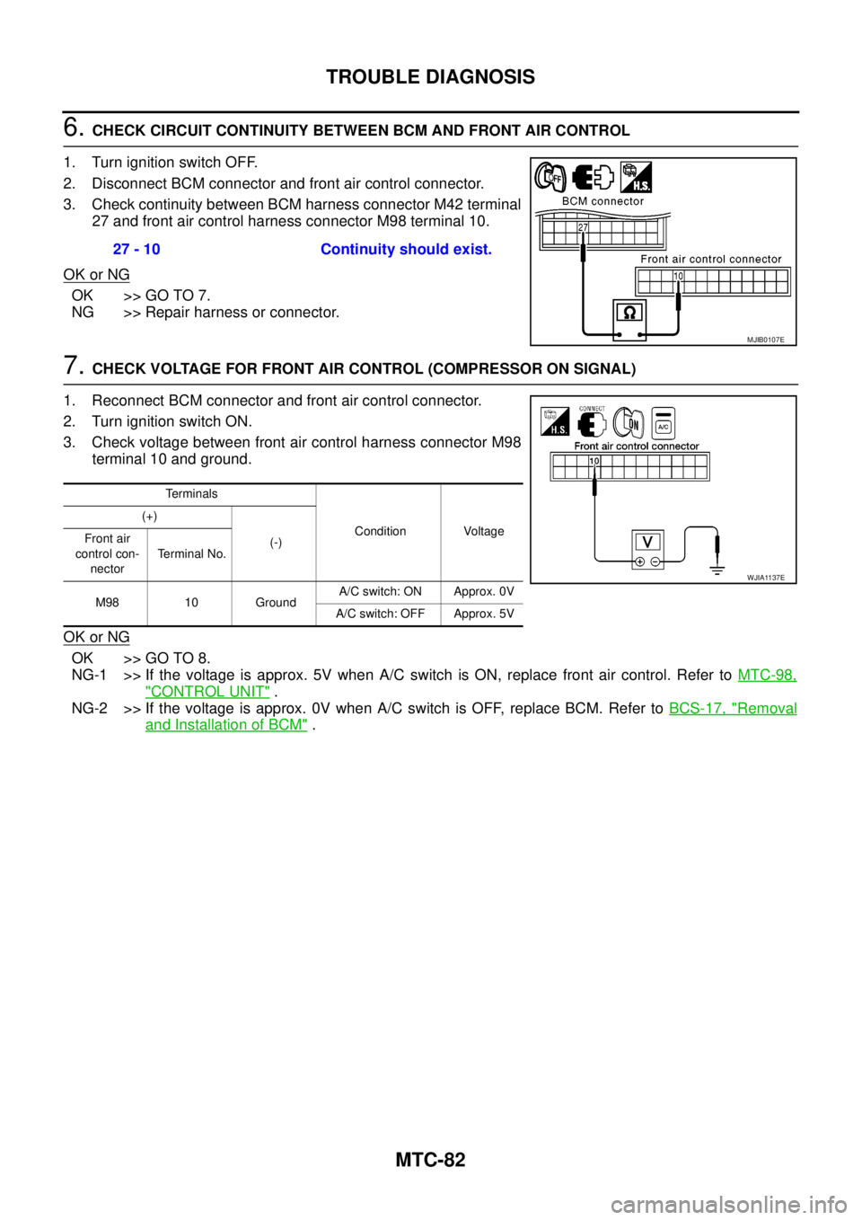
6.CHECK CIRCUIT CONTINUITY BETWEEN BCM AND FRONT AIR CONTROL
1. Turn ignition switch OFF.
2. Disconnect BCM connector and front air control connector.
3. Check continuity between BCM harness connector M42 terminal
27 and front air control harness connector M98 terminal 10.
OK or NG
OK >> GO TO 7.
NG >> Repair harness or connector.
7.CHECK VOLTAGE FOR FRONT AIR CONTROL (COMPRESSOR ON SIGNAL)
1. Reconnect BCM connector and front air control connector.
2. Turn ignition switch ON.
3. Check voltage between front air control harness connector M98
terminal 10 and ground.
OK or NG
OK >> GO TO 8.
NG-1 >> If the voltage is approx. 5V when A/C switch is ON, replace front air control. Refer toMTC-98,
"CONTROL UNIT".
NG-2 >> If the voltage is approx. 0V when A/C switch is OFF, replace BCM. Refer toBCS-17, "
Removal
and Installation of BCM". 27 - 10 Continuity should exist.
MJIB0107E
Terminals
Condition Voltage (+)
(-) Front air
control con-
nectorTerminal No.
M98 10 GroundA/C switch: ON Approx. 0V
A/C switch: OFF Approx. 5V
WJIA1137E
Page 2471 of 3171

MTC-84
TROUBLE DIAGNOSIS
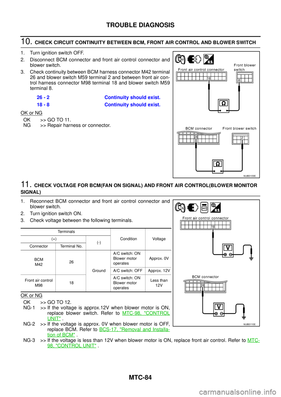
10.CHECK CIRCUIT CONTINUITY BETWEEN BCM, FRONT AIR CONTROL AND BLOWER SWITCH
1. Turn ignition switch OFF.
2. Disconnect BCM connector and front air control connector and
blower switch.
3. Check continuity between BCM harness connector M42 terminal
26 and blower switch M59 terminal 2 and between front air con-
trol harness connector M98 terminal 18 and blower switch M59
terminal 8.
OK or NG
OK >> GO TO 11.
NG >> Repair harness or connector.
11 .CHECK VOLTAGE FOR BCM(FAN ON SIGNAL) AND FRONT AIR CONTROL(BLOWER MONITOR
SIGNAL)
1. Reconnect BCM connector and front air control connector and
blower switch.
2. Turn ignition switch ON.
3. Check voltage between the following terminals.
OK or NG
OK >> GO TO 12.
NG-1 >> If the voltage is approx.12V when blower motor is ON,
replace blower switch. Refer toMTC-98, "
CONTROL
UNIT".
NG-2 >> If the voltage is approx. 0V when blower motor is OFF,
replace BCM. Refer toBCS-17, "
Removal and Installa-
tion of BCM".
NG-3 >> If the voltage is less than 12V when blower motor is ON, replace front air control. Refer toMTC-
98, "CONTROL UNIT". 26 - 2 Continuity should exist.
18 - 8 Continuity should exist.
MJIB0109E
Terminals
Condition Voltage (+)
(-)
Connector Terminal No.
BCM
M4226
GroundA/C switch: ON
Blower motor
operatesApprox. 0V
A/C switch: OFF Approx. 12V
Front air control
M9818A/C switch: ON
Blower motor
operatesLess than
12V
MJIB0110E
Page 2483 of 3171

MTC-96
TROUBLE DIAGNOSIS
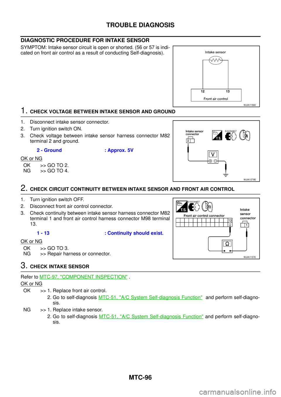
DIAGNOSTIC PROCEDURE FOR INTAKE SENSOR
SYMPTOM: Intake sensor circuit is open or shorted. (56 or 57 is indi-
cated on front air control as a result of conducting Self-diagnosis).
1.CHECK VOLTAGE BETWEEN INTAKE SENSOR AND GROUND
1. Disconnect intake sensor connector.
2. Turn ignition switch ON.
3. Check voltage between intake sensor harness connector M82
terminal 2 and ground.
OK or NG
OK >> GO TO 2.
NG >> GO TO 4.
2.CHECK CIRCUIT CONTINUITY BETWEEN INTAKE SENSOR AND FRONT AIR CONTROL
1. Turn ignition switch OFF.
2. Disconnect front air control connector.
3. Check continuity between intake sensor harness connector M82
terminal 1 and front air control harness connector M98 terminal
13.
OK or NG
OK >> GO TO 3.
NG >> Repair harness or connector.
3.CHECK INTAKE SENSOR
Refer toMTC-97, "
COMPONENT INSPECTION".
OK or NG
OK >> 1. Replace front air control.
2. Go to self-diagnosisMTC-51, "
A/C System Self-diagnosis Function"and perform self-diagno-
sis.
NG >> 1. Replace intake sensor.
2. Go to self-diagnosisMTC-51, "
A/C System Self-diagnosis Function"and perform self-diagno-
sis.
WJIA1156E
2 - Ground : Approx. 5V
WJIA1278E
1 - 13 : Continuity should exist.
WJIA1157E
Page 2484 of 3171

TROUBLE DIAGNOSIS
MTC-97
C
D
E
F
G
H
I
K
L
MA
B
MTC
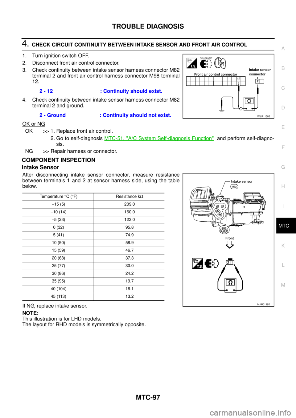
4.CHECK CIRCUIT CONTINUITY BETWEEN INTAKE SENSOR AND FRONT AIR CONTROL
1. Turn ignition switch OFF.
2. Disconnect front air control connector.
3. Check continuity between intake sensor harness connector M82
terminal 2 and front air control harness connector M98 terminal
12.
4. Check continuity between intake sensor harness connector M82
terminal 2 and ground.
OK or NG
OK >> 1. Replace front air control.
2. Go to self-diagnosisMTC-51, "
A/C System Self-diagnosis Function"and perform self-diagno-
sis.
NG >> Repair harness or connector.
COMPONENT INSPECTION
Intake Sensor
After disconnecting intake sensor connector, measure resistance
between terminals 1 and 2 at sensor harness side, using the table
below.
If NG, replace intake sensor.
NOTE:
This illustration is for LHD models.
The layout for RHD models is symmetrically opposite.2 - 12 : Continuity should exist.
2 - Ground : Continuity should not exist.
WJIA1158E
Temperature°C(°F) Resistance kW
-15 (5) 209.0
-10 (14) 160.0
-5 (23) 123.0
0 (32) 95.8
5 (41) 74.9
10 (50) 58.9
15 (59) 46.7
20 (68) 37.3
25 (77) 30.0
30 (86) 24.2
35 (95) 19.7
40 (104) 16.1
45 (113) 13.2
MJIB0199E
Page 2530 of 3171

PG-1
POWER SUPPLY, GROUND & CIRCUIT ELEMENTS
K ELECTRICAL
CONTENTS
C
D
E
F
G
H
I
J
L
M
SECTIONPG
A
B
PG
POWER SUPPLY, GROUND & CIRCUIT ELEMENTS
PRECAUTIONS .......................................................... 3
Precautions for Supplemental Restraint System
(SRS)“AIRBAG”and“SEATBELTPRE-TEN-
SIONER” .................................................................. 3
Wiring Diagrams and Trouble Diagnosis .................. 3
POWER SUPPLY ROUTING CIRCUIT ...................... 4
Schematic ................................................................ 4
Wiring Diagram — POWER — ................................. 5
BATTERY POWER SUPPLY — IGNITION SW.
IN ANY POSITION ................................................ 5
ACCESSORY POWER SUPPLY — IGNITION
SW. IN ACC OR ON ............................................ 10
IGNITION POWER SUPPLY — IGNITION SW.
IN ON ................................................................... 11
IGNITION POWER SUPPLY — IGNITION SW.
IN ON AND/OR START ....................................... 12
IPDM E/R (INTELLIGENT POWER DISTRIBUTION
MODULE ENGINE ROOM) ...................................... 14
System Description ................................................ 14
SYSTEMS CONTROLLED BY IPDM E/R ........... 14
CAN COMMUNICATION LINE CONTROL ......... 14
IPDM E/R STATUS CONTROL ........................... 15
CAN Communication System Description .............. 15
Function of Detecting Ignition Relay Malfunction ... 15
CONSULT-II Function (IPDM E/R) ......................... 16
CONSULT-II BASIC OPERATION ...................... 16
SELF-DIAGNOSTIC RESULTS .......................... 17
DATA MONITOR ................................................. 17
CAN DIAG SUPPORT MNTR ............................. 18
ACTIVE TEST ..................................................... 18
Auto Active Test ..................................................... 19
DESCRIPTION .................................................... 19
OPERATION PROCEDURE ............................... 19
INSPECTION IN AUTO ACTIVE TEST MODE... 20
Schematic .............................................................. 22
IPDM E/R Terminal Arrangement ........................... 23
Check IPDM E/R Power Supply and Ground Circuit... 24Inspection with CONSULT-II (Self-Diagnosis) ........ 25
Removal and Installation of IPDM E/R ................... 26
REMOVAL ........................................................... 26
INSTALLATION ................................................... 26
GROUND CIRCUIT ................................................... 27
Ground Distribution ................................................. 27
MAIN HARNESS ................................................. 27
ENGINE ROOM HARNESS ................................ 30
ENGINE CONTROL HARNESS .......................... 34
BODY HARNESS (LH SIDE) .............................. 35
BODY HARNESS (RH SIDE) .............................. 36
DEFOGGER CABLE ........................................... 37
HARNESS ................................................................. 38
Harness Layout ...................................................... 38
HOW TO READ HARNESS LAYOUT ................. 38
OUTLINE/DOUBLE CAB MODELS .................... 39
OUTLINE/KING CAB MODELS .......................... 40
MAIN HARNESS/LHD MODELS ......................... 41
MAIN HARNESS/RHD MODELS ........................ 44
ENGINE ROOM HARNESS/LHD MODELS ........ 47
ENGINE ROOM HARNESS/RHD MODELS ....... 49
ENGINE CONTROL HARNESS .......................... 51
CHASSIS HARNESS .......................................... 53
BODY HARNESS (LH SIDE)/DOUBLE CAB
MODELS ............................................................. 54
BODY HARNESS (RH SIDE)/DOUBLE CAB
MODELS ............................................................. 56
BODY HARNESS (LH SIDE)/KING CAB MOD-
ELS ...................................................................... 58
BODY HARNESS (RH SIDE)/KING CAB MOD-
ELS ...................................................................... 60
ROOM LAMP HARNESS .................................... 62
FRONT DOOR LH HARNESS/LHD MODELS .... 63
FRONT DOOR RH HARNESS/LHD MODELS ... 63
FRONT DOOR LH HARNESS/RHD MODELS ... 64
FRONT DOOR RH HARNESS/RHD MODELS ... 64
REAR DOOR LH HARNESS/DOUBLE CAB
MODELS ............................................................. 65
REAR DOOR RH HARNESS/DOUBLE CAB
MODELS ............................................................. 65
Page 2534 of 3171
POWER SUPPLY ROUTING CIRCUIT
PG-5
C
D
E
F
G
H
I
J
L
MA
B
PG
Wiring Diagram — POWER —EKS00LIW
BATTERY POWER SUPPLY — IGNITION SW. IN ANY POSITION
MKWA3810E
Page 2539 of 3171
PG-10
POWER SUPPLY ROUTING CIRCUIT
ACCESSORY POWER SUPPLY — IGNITION SW. IN ACC OR ON
MKWA3815E
Page 2540 of 3171
POWER SUPPLY ROUTING CIRCUIT
PG-11
C
D
E
F
G
H
I
J
L
MA
B
PG
IGNITION POWER SUPPLY — IGNITION SW. IN ON
MKWA3816E