2005 NISSAN NAVARA ignition
[x] Cancel search: ignitionPage 2854 of 3171
CHARGING SYSTEM
SC-21
C
D
E
F
G
H
I
J
L
MA
B
SC
2.BATTERY VOLTAGE INSPECTION
1. Turn ignition switch OFF.
2. Disconnect alternator connector.
3. Turn ignition switch ON.
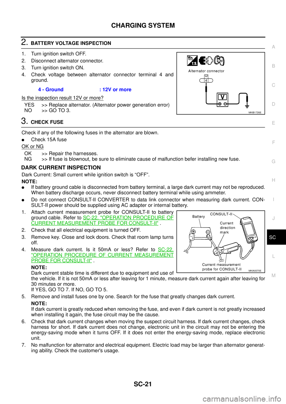
4. Check voltage between alternator connector terminal 4 and
ground.
Is the inspection result 12V or more?
YES >> Replace alternator. (Alternator power generation error)
NO >> GO TO 3.
3.CHECK FUSE
Check if any of the following fuses in the alternator are blown.
lCheck 15A fuse
OK or NG
OK >> Repair the harnesses.
NG >> If fuse is blownout, be sure to eliminate cause of malfunction befer installing new fuse.
DARK CURRENT INSPECTION
Dark Current: Small current while ignition switch is “OFF”.
NOTE:
lIf battery ground cable is disconnected from battery terminal, a large dark current may not be reproduced.
When battery discharge occurs, never disconnect battery terminal while using ammeter.
lDo not connect CONSULT-II CONVERTER to data link connector when measuring dark current. CON-
SULT-II power should be supplied using AC adapter or internal battery.
1. Attach current measurement probe for CONSULT-II to battery
ground cable. Refer toSC-22, "
OPERATION PROCEDURE OF
CURRENT MEASUREMENT PROBE FOR CONSULT-II".
2. Check that all electrical equipment is turned OFF.
3. Remove key. Close and lock doors. Check that room lamp turns
off.
4. Measure dark current. Is it 50mA or less? Refer toSC-22,
"OPERATION PROCEDURE OF CURRENT MEASUREMENT
PROBE FOR CONSULT-II".
NOTE:
Dark current stable time is different due to equipment and use of
the vehicle. If it is not 50mA or less after leaving for 1 minute, measure dark current again after leaving for
30 minutes or more.
If YES, GO TO 7. If NO, GO TO 5.
5. Remove and install fuses one by one. Search for the fuse that greatly changes dark current.
NOTE:
If dark current is greatly reduced when removing the fuse, and even if dark current is not greatly increased
when installing it again, the fuse circuit may be the cause.
6. Check that dark current changes when moving the suspect circuit harness. If dark current changes, check
harness for short. If dark current does not change, electronic unit in the circuit may not be entering the
energy-saving mode when it turns OFF. If it does not enter the energy-saving mode, replace electronic
unit.
7. No malfunction for alternator and electrical equipment. Electric load may be larger than alternator generat-
ing ability. Check the customer's usage.4 - Ground : 12V or more
MKIB1726E
MKIA0070E
Page 2860 of 3171

STARTING SYSTEM
SC-27
C
D
E
F
G
H
I
J
L
MA
B
SC
STARTING SYSTEMPFP:00011
System DescriptionEKS00MZJ
A/T MODELS
Power is supplied at all times:
lto starter motor terminal 1 and
lthrough 40A fusible link (letterJ, located in the fuse and fusible link box)
lto ignition switch terminal 1.
with the ignition switch in the START position, power is supplied:
lfrom ignition switch terminal 5
lto IPDM E/R terminal 21.
With the ignition switch in the ON or START position, power is supplied to IPDM E/R CPU, and
the selector lever in the P or N position, power is supplied:
lthrough A/T assembly terminal 9
lto IPDM E/R terminal 48.
Ground is supplied at all times:
lto IPDM E/R terminals 38 and 59
lfrom body grounds E21, E41 and E61.
Then the starter relay is turned ON.
The IPDM E/R starter relay is energized and power is supplied:
lfrom terminal 19 of IPDM E/R
lto terminal 2 of the starter motor.
The starter motor plunger closes and provides a closed circuit between the battery and the starter motor. The
starter motor is grounded to the cylinder block. With power and ground supplied, the starter motor operates.
M/T MODELS
Power is supplied at all times:
lto starter motor terminal 1 and
lthrough 40A fusible link (letterJ, located in the fuse and fusible link box)
lto ignition switch terminal 1.
with the ignition switch in the START position, power is supplied:
lfrom ignition switch terminal 5
lto IPDM E/R terminal 21.
With the start signal is input to IPDM E/R CPU, power is supplied:
lthrough IPDM E/R terminal 14
lto IPDM E/R terminal 48.
Ground is supplied at all times:
lto IPDM E/R terminals 38 and 59
lfrom body grounds E21, E41 and E61.
Then the starter relay is turned ON.
The IPDM E/R starter relay is energized and power is supplied:
lfrom terminal 19 of IPDM E/R
lto terminal 2 of the starter motor.
The starter motor plunger closes and provides a closed circuit between the battery and the starter motor. The
starter motor is grounded to the cylinder block. With power and ground supplied, the starter motor operates.
Page 2894 of 3171
FRONT SEAT
SE-23
C
D
E
F
G
H
J
K
L
MA
B
SE
Removal and InstallationEIS00C62
REMOVAL
When removing or installing the seat trim, handle it carefully to keep dirt out and avoid damage.
CAUTION:
lBefore removing the front seat, turn the ignition switch off, disconnect both battery cables and
wait at least 3 minutes.
lWhen checking the power seat circuit for continuity using a circuit tester, do not confuse its con-
nector with the side air bag module connector. Such an error may cause the air bag to deploy.
lDo not drop, tilt, or bump the side air bag module while installing the seat. Always handle it with
care.
lAfter front side air bag module inflates, front seatback assembly must be replaced.
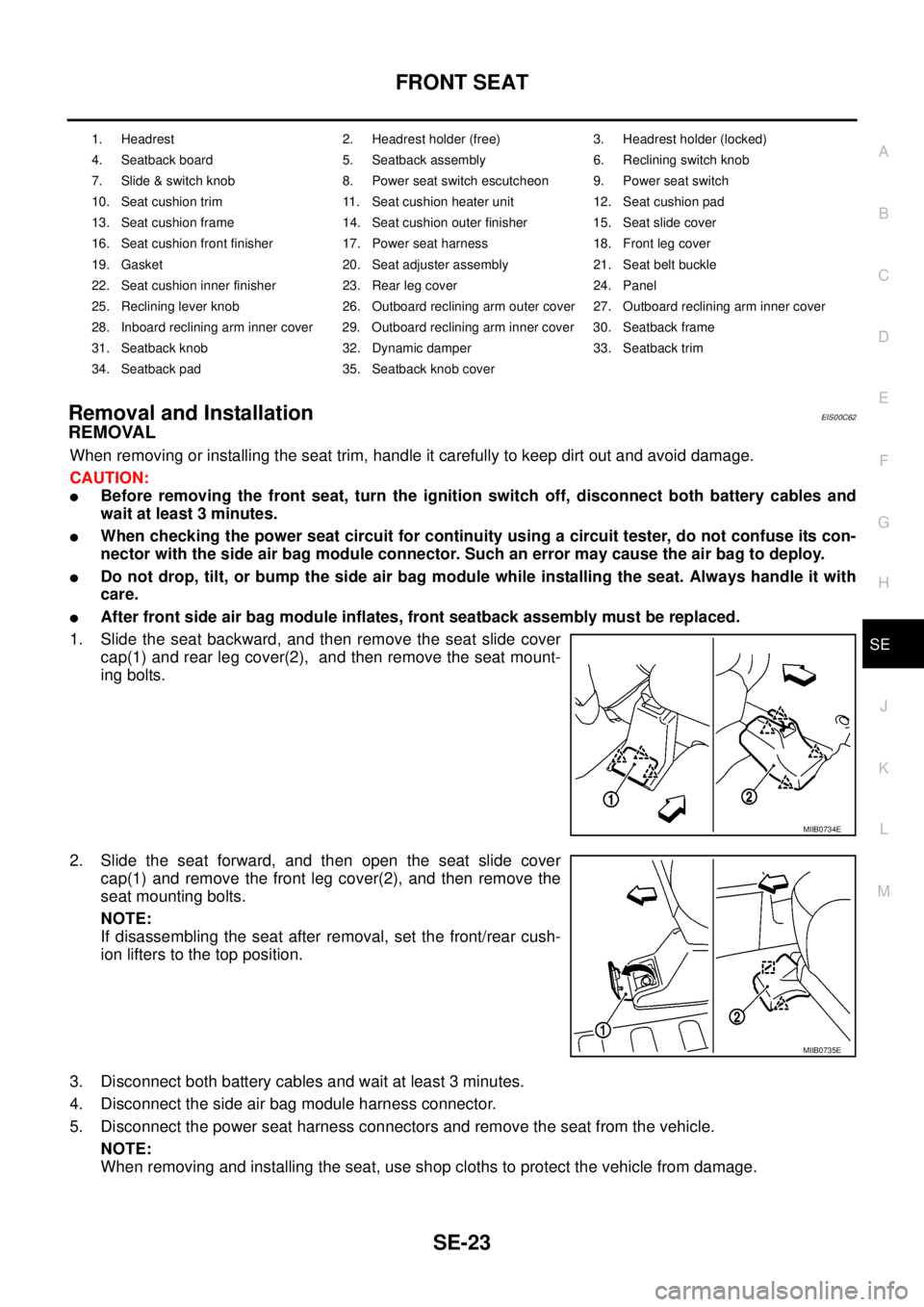
1. Slide the seat backward, and then remove the seat slide cover
cap(1) and rear leg cover(2), and then remove the seat mount-
ing bolts.
2. Slide the seat forward, and then open the seat slide cover
cap(1) and remove the front leg cover(2), and then remove the
seat mounting bolts.
NOTE:
If disassembling the seat after removal, set the front/rear cush-
ion lifters to the top position.
3. Disconnect both battery cables and wait at least 3 minutes.
4. Disconnect the side air bag module harness connector.
5. Disconnect the power seat harness connectors and remove the seat from the vehicle.
NOTE:
When removing and installing the seat, use shop cloths to protect the vehicle from damage.
1. Headrest 2. Headrest holder (free) 3. Headrest holder (locked)
4. Seatback board 5. Seatback assembly 6. Reclining switch knob
7. Slide & switch knob 8. Power seat switch escutcheon 9. Power seat switch
10. Seat cushion trim 11. Seat cushion heater unit 12. Seat cushion pad
13. Seat cushion frame 14. Seat cushion outer finisher 15. Seat slide cover
16. Seat cushion front finisher 17. Power seat harness 18. Front leg cover
19. Gasket 20. Seat adjuster assembly 21. Seat belt buckle
22. Seat cushion inner finisher 23. Rear leg cover 24. Panel
25. Reclining lever knob 26. Outboard reclining arm outer cover 27. Outboard reclining arm inner cover
28. Inboard reclining arm inner cover 29. Outboard reclining arm inner cover 30. Seatback frame
31. Seatback knob 32. Dynamic damper 33. Seatback trim
34. Seatback pad 35. Seatback knob cover
MIIB0734E
MIIB0735E
Page 2912 of 3171
PRECAUTIONS
SRS-3
C
D
E
F
G
I
J
K
L
MA
B
SRS
PRECAUTIONSPFP:00001
Precautions for Supplemental Restraint System (SRS) “AIR BAG” and “SEAT
BELT PRE-TENSIONER”
EHS001Y8
The Supplemental Restraint System such as “AIR BAG” and “SEAT BELT PRE-TENSIONER”, used along
with a front seat belt, helps to reduce the risk or severity of injury to the driver and front passenger for certain
types of collision. Information necessary to service the system safely is included in the SRS and SB section of
this Service Manual.
WARNING:
lTo avoid rendering the SRS inoperative, which could increase the risk of personal injury or death
in the event of a collision which would result in air bag inflation, all maintenance must be per-
formed by an authorized NISSAN/INFINITI dealer.
lImproper maintenance, including incorrect removal and installation of the SRS, can lead to per-
sonal injury caused by unintentional activation of the system. For removal of Spiral Cable and Air
Bag Module, see the SRS section.
lDo not use electrical test equipment on any circuit related to the SRS unless instructed to in this
Service Manual. SRS wiring harnesses can be identified by yellow and/or orange harnesses or
harness connectors.
Precautions for SRS “AIR BAG” and “SEAT BELT PRE-TENSIONER” ServiceEHS001Y9
lDo not use electrical test equipment to check SRS circuits unless instructed to in this Service Manual.
lBefore servicing the SRS, turn ignition switch OFF, disconnect both battery cables and wait at least 3 min-
utes.
For approximately 3 minutes after the cables are removed, it is still possible for the air bag and seat belt
pre-tensioner to deploy. Therefore, do not work on any SRS connectors or wires until at least 3 minutes
have passed.
lDiagnosis sensor unit must always be installed with their arrow marks “Ü” pointing towards the front of the
vehicle for proper operation. Also check diagnosis sensor unit for cracks, deformities or rust before instal-
lation and replace as required.
lThe spiral cable must be aligned with the neutral position since its rotations are limited. Do not attempt to
turn steering wheel or column after removal of steering gear.
lHandle air bag module carefully. Always place driver and front passenger air bag modules with the pad
side facing upward and place front side air bag module standing with stud bolt side setting bottom.
lConduct self-diagnosis to check entire SRS for proper function after replacing any components.
lAfter air bag inflates, the front instrument panel assembly should be replaced if damaged.
lAlways replace instrument panel pad following front passenger air bag deployment.
Precautions for Trouble DiagnosisEHS001YA
When you read wiring diagrams, refer to the following:
lGI-15, "How to Read Wiring Diagrams"in GI section
lPG-4, "POWER SUPPLY ROUTING CIRCUIT"in PG section
When you perform trouble diagnosis, refer to the following:
lGI-11, "How to Follow Trouble Diagnoses"in GI section
lGI-24, "How to Perform Efficient Diagnosis for an Electrical Incident"in GI section
Check for any service bulletins before servicing the vehicle.
Page 2915 of 3171
SRS-6
SUPPLEMENTAL RESTRAINT SYSTEM (SRS)
SUPPLEMENTAL RESTRAINT SYSTEM (SRS)
PFP:28556
SRS ConfigurationEHS001XA
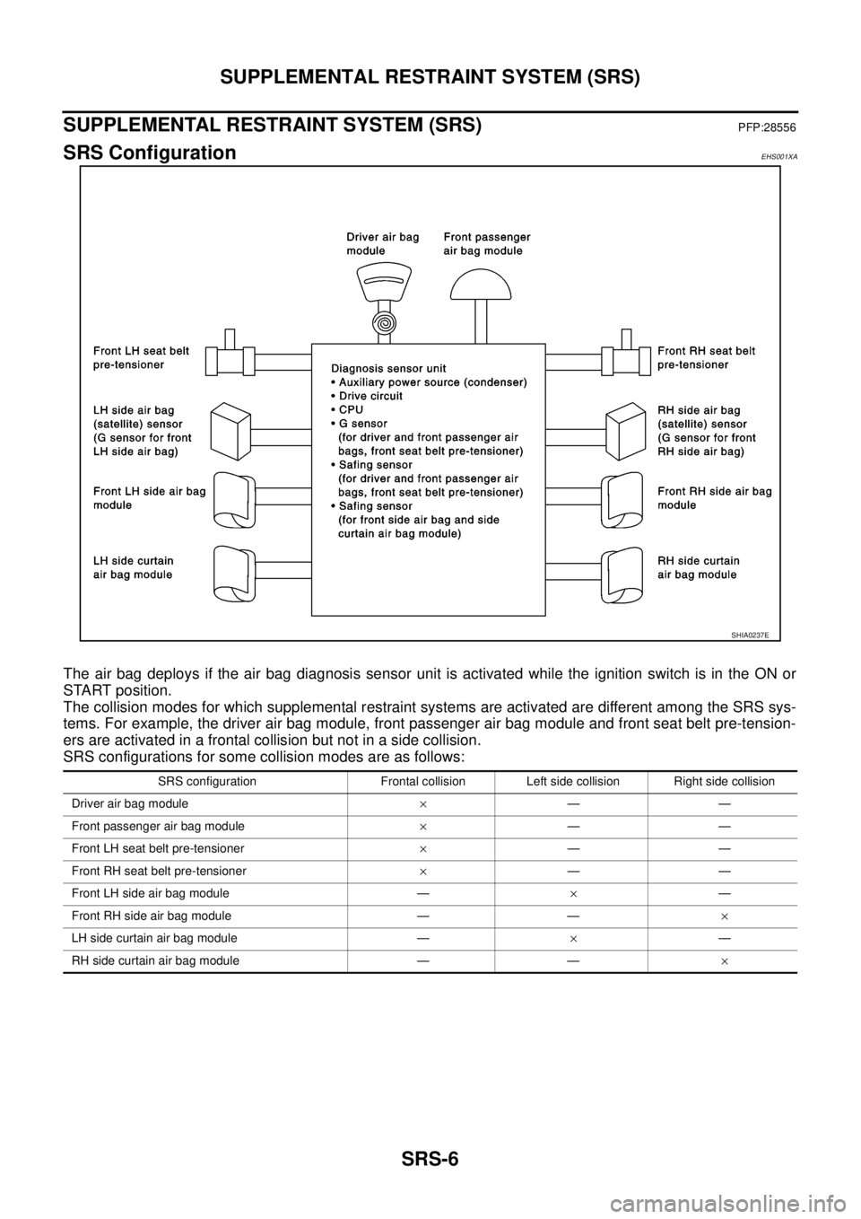
The air bag deploys if the air bag diagnosis sensor unit is activated while the ignition switch is in the ON or
START position.
The collision modes for which supplemental restraint systems are activated are different among the SRS sys-
tems. For example, the driver air bag module, front passenger air bag module and front seat belt pre-tension-
ers are activated in a frontal collision but not in a side collision.
SRS configurations for some collision modes are as follows:
SHIA0237E
SRS configuration Frontal collision Left side collision Right side collision
Driver air bag module´——
Front passenger air bag module´——
Front LH seat belt pre-tensioner´——
Front RH seat belt pre-tensioner´——
Front LH side air bag module —´—
Front RH side air bag module — —´
LH side curtain air bag module —´—
RH side curtain air bag module — —´
Page 2926 of 3171
![NISSAN NAVARA 2005 Repair Workshop Manual TROUBLE DIAGNOSIS
SRS-17
C
D
E
F
G
I
J
K
L
MA
B
SRS
HOW TO ERASE SELF-DIAGNOSIS RESULTS
l“SELF-DIAG [CURRENT]”
A current self-diagnosis result is displayed on the CONSULT-II
screen in real time.
A NISSAN NAVARA 2005 Repair Workshop Manual TROUBLE DIAGNOSIS
SRS-17
C
D
E
F
G
I
J
K
L
MA
B
SRS
HOW TO ERASE SELF-DIAGNOSIS RESULTS
l“SELF-DIAG [CURRENT]”
A current self-diagnosis result is displayed on the CONSULT-II
screen in real time.
A](/manual-img/5/57362/w960_57362-2925.png)
TROUBLE DIAGNOSIS
SRS-17
C
D
E
F
G
I
J
K
L
MA
B
SRS
HOW TO ERASE SELF-DIAGNOSIS RESULTS
l“SELF-DIAG [CURRENT]”
A current self-diagnosis result is displayed on the CONSULT-II
screen in real time.
After the malfunction is repaired completely, no malfunction is
detected on “SELF-DIAG [CURRENT]”.
l“SELF-DIAG [PAST]”
Return to the “SELF-DIAG [CURRENT]” CONSULT-II screen by
touching “BACK” key of CONSULT-II and select “SELF-DIAG
[PAST]” in SELECT DIAG MODE. Touch “ERASE” in “SELF-
DIAG [PAST]” mode.
NOTE:
If the memory of the malfunction in “SELF-DIAG [PAST]” is
not erased, the User mode will continue to show the system
malfunction by the operation of the warning lamp even if
the malfunction is repaired completely.
l“TROUBLE DIAG RECORD”
The memory of “TROUBLE DIAG RECORD” cannot be erased.
Self-Diagnosis Function (Without CONSULT-II)EHS001XM
lThe reading of these results is accomplished using one of two modes — “User mode” and “Diagnosis
mode”.
lAfter a malfunction is repaired, turn the ignition switch OFF for at least one second, then back ON. Diag-
nosis mode returns to the User mode. At that time, the self-diagnostic result is cleared.
HOW TO CHANGE SELF-DIAGNOSIS MODE
SRS701
SRS702
SHIA0183E
Page 2927 of 3171
SRS-18
TROUBLE DIAGNOSIS
HOW TO ERASE SELF-DIAGNOSIS RESULTS
After a malfunction is repaired, turn the ignition switch OFF for at least one second, then back ON. Diagnosis
mode returns to the User mode. At that time, the self-diagnostic result is cleared.
SRS Operation CheckEHS001XN
DIAGNOSTIC PROCEDURE 1
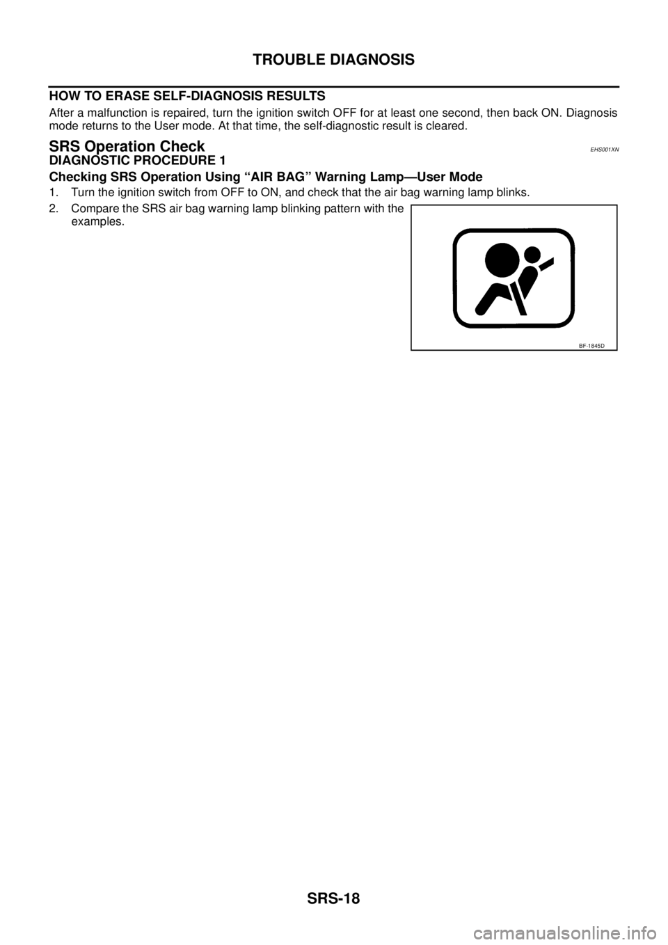
Checking SRS Operation Using “AIR BAG” Warning Lamp—User Mode
1. Turn the ignition switch from OFF to ON, and check that the air bag warning lamp blinks.
2. Compare the SRS air bag warning lamp blinking pattern with the
examples.
BF-1845D
Page 2929 of 3171
SRS-20
TROUBLE DIAGNOSIS
Trouble Diagnosis With CONSULT-II
EHS001XO
DIAGNOSTIC PROCEDURE 2
CAUTION:
If CONSULT-II is used with no connection of CONSULT-II CONVERTER, malfunction might be detected
in self-diagnosis depending on control unit which carry out CAN communication.
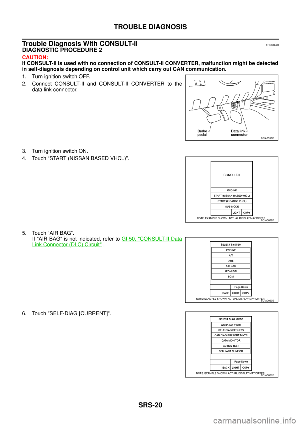
1. Turn ignition switch OFF.
2. Connect CONSULT-II and CONSULT-II CONVERTER to the
data link connector.
3. Turn ignition switch ON.
4. Touch “START (NISSAN BASED VHCL)”.
5. Touch “AIR BAG”.
If "AIR BAG" is not indicated, refer toGI-50, "
CONSULT-II Data
Link Connector (DLC) Circuit".
6. Touch "SELF-DIAG [CURRENT]".
BBIA0538E
BCIA0029E
BCIA0030E
BCIA0031E