2005 NISSAN NAVARA ignition
[x] Cancel search: ignitionPage 3012 of 3171
TROUBLE DIAGNOSIS
TF-45
C
E
F
G
H
I
J
K
L
MA
B
TF
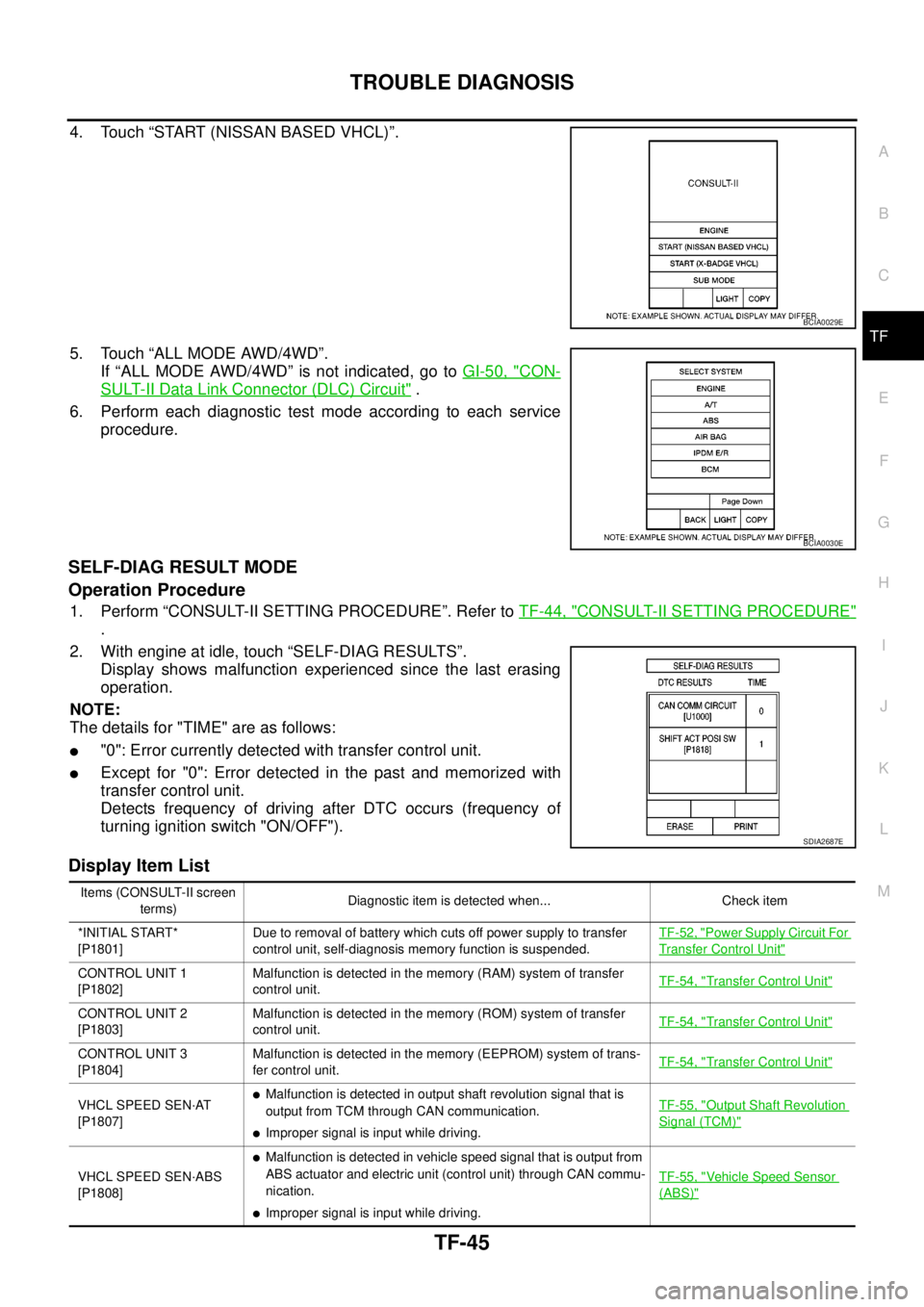
4. Touch “START (NISSAN BASED VHCL)”.
5. Touch “ALL MODE AWD/4WD”.
If “ALL MODE AWD/4WD” is not indicated, go toGI-50, "
CON-
SULT-II Data Link Connector (DLC) Circuit".
6. Perform each diagnostic test mode according to each service
procedure.
SELF-DIAG RESULT MODE
Operation Procedure
1. Perform “CONSULT-II SETTING PROCEDURE”. Refer toTF-44, "CONSULT-II SETTING PROCEDURE"
.
2. With engine at idle, touch “SELF-DIAG RESULTS”.
Display shows malfunction experienced since the last erasing
operation.
NOTE:
The details for "TIME" are as follows:
l"0": Error currently detected with transfer control unit.
lExcept for "0": Error detected in the past and memorized with
transfer control unit.
Detects frequency of driving after DTC occurs (frequency of
turning ignition switch "ON/OFF").
Display Item List
BCIA0029E
BCIA0030E
SDIA2687E
Items (CONSULT-II screen
terms)Diagnostic item is detected when... Check item
*INITIAL START*
[P1801]Due to removal of battery which cuts off power supply to transfer
control unit, self-diagnosis memory function is suspended.TF-52, "
Power Supply Circuit For
Transfer Control Unit"
CONTROL UNIT 1
[P1802]Malfunction is detected in the memory (RAM) system of transfer
control unit.TF-54, "Transfer Control Unit"
CONTROL UNIT 2
[P1803]Malfunction is detected in the memory (ROM) system of transfer
control unit.TF-54, "Transfer Control Unit"
CONTROL UNIT 3
[P1804]Malfunction is detected in the memory (EEPROM) system of trans-
fer control unit.TF-54, "Transfer Control Unit"
VHCL SPEED SEN·AT
[P1807]lMalfunction is detected in output shaft revolution signal that is
output from TCM through CAN communication.
lImproper signal is input while driving.TF-55, "
Output Shaft Revolution
Signal (TCM)"
VHCL SPEED SEN·ABS
[P1808]
lMalfunction is detected in vehicle speed signal that is output from
ABS actuator and electric unit (control unit) through CAN commu-
nication.
lImproper signal is input while driving.TF-55, "
Vehicle Speed Sensor
(ABS)"
Page 3016 of 3171
TROUBLE DIAGNOSIS
TF-49
C
E
F
G
H
I
J
K
L
MA
B
TF
Self-Diagnostic ProcedureEDS0031X
SELF-DIAGNOSTIC PROCEDURE (WITH CONSULT-II)
Refer toTF-45, "SELF-DIAG RESULT MODE".
SELF-DIAGNOSTIC PROCEDURE (WITHOUT CONSULT-II)
Description
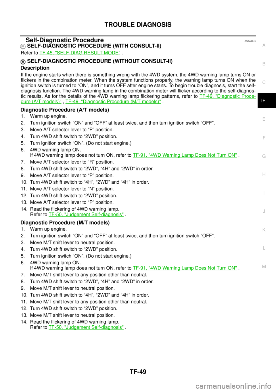
If the engine starts when there is something wrong with the 4WD system, the 4WD warning lamp turns ON or
flickers in the combination meter. When the system functions properly, the warning lamp turns ON when the
ignition switch is turned to “ON”, and it turns OFF after engine starts. To begin trouble diagnosis, start the self-
diagnosis function. The 4WD warning lamp in the combination meter will flicker according to the self-diagnos-
tic results. As for the details of the 4WD warning lamp flickering patterns, refer toTF-49, "
Diagnostic Proce-
dure (A/T models)",TF-49, "Diagnostic Procedure (M/T models)".
Diagnostic Procedure (A/T models)
1. Warm up engine.
2. Turn ignition switch “ON” and “OFF” at least twice, and then turn ignition switch “OFF”.
3. Move A/T selector lever to “P” position.
4. Turn 4WD shift switch to “2WD” position.
5. Turn ignition switch “ON”. (Do not start engine.)
6. 4WD warning lamp ON.
If 4WD warning lamp does not turn ON, refer toTF-91, "
4WD Warning Lamp Does Not Turn ON".
7. Move A/T selector lever to “R” position.
8. Turn 4WD shift switch to “2WD”, “4H” and “2WD” in order.
9. Move A/T selector lever to “P” position.
10. Turn 4WD shift switch to “4H”, “2WD” and “4H” in order.
11. Move A/T selector lever to “N” position.
12. Turn 4WD shift switch to “2WD” position.
13. Move A/T selector lever to “P” position.
14. Read the flickering of 4WD warning lamp.
Refer toTF-50, "
Judgement Self-diagnosis".
Diagnostic Procedure (M/T models)
1. Warm up engine.
2. Turn ignition switch “ON” and “OFF” at least twice, and then turn ignition switch “OFF”.
3. Move M/T shift lever to neutral position.
4. Turn 4WD shift switch to “2WD” position.
5. Turn ignition switch “ON”. (Do not start engine.)
6. 4WD warning lamp ON.
If 4WD warning lamp does not turn ON, refer toTF-91, "
4WD Warning Lamp Does Not Turn ON".
7. Move M/T shift lever to any position other than neutral.
8. Turn 4WD shift switch to “2WD”, “4H” and “2WD” in order.
9. Move M/T shift lever to neutral position.
10. Turn 4WD shift switch to “4H”, “2WD” and “4H” in order.
11. Move M/T shift lever to any position other than neutral.
12. Turn 4WD shift switch to “2WD” position.
13. Move M/T shift lever to neutral position.
14. Read the flickering of 4WD warning lamp.
Refer toTF-50, "
Judgement Self-diagnosis".
Page 3018 of 3171

TROUBLE DIAGNOSIS
TF-51
C
E
F
G
H
I
J
K
L
MA
B
TFNOTE:
If flickering pattern 12 or 13 is displayed, first erase self-diagnostic results. Flickering pattern 12 or 13 may be displayed after installing
transfer control unit or transfer assembly.
ERASE SELF-DIAGNOSIS
lIn order to make it easier to find the cause of hard-to-duplicate malfunctions, malfunction information is
stored into the control unit as necessary during use by the user. This memory is not erased no matter how
many times the ignition switch is turned ON and OFF.
lHowever, this information is erased by turning ignition switch “OFF” after performing self-diagnostics or by
erasing the memory using the CONSULT-II.
Repeats flickering
every 0.25 sec.Data erase displaylPower supply malfunction of memory back-up.
lBattery is disconnected for a long time.
lBattery performance is poor.TF-52, "
Power Supply
Circuit For Transfer
Control Unit"
Repeats flickering
every 2 to 5 sec.— Circuits that the self-diagnosis covers have no malfunction. —
No flickeringPNP switch or 4WD
shift switchPNP switch or 4WD shift switch circuit is shorted or open.TF-66, "
PNP Switch
Signal (TCM)"orTF-
59, "4WD Shift Switch"
Flickering pattern Items Diagnostic item is detected when... Check item
Page 3019 of 3171

TF-52
TROUBLE DIAGNOSIS FOR SYSTEM
TROUBLE DIAGNOSIS FOR SYSTEM
PFP:00000
Power Supply Circuit For Transfer Control UnitEDS0031Y
CONSULT-II REFERENCE VALUE IN DATA MONITOR MODE
Data are reference value.
TRANSFER CONTROL UNIT TERMINALS AND REFERENCE VALUE
Data are reference value and are measured between each terminal and ground.
CAUTION:
When using a circuit tester to measure voltage for inspection, be sure not to extend forcibly any connector terminals.Monitored item [Unit] Content Condition Display value
BATTERY VOLT [V]Power supply voltage for
transfer control unitIgnition switch: ON Battery voltage
Te r m i n a lWire
colorItem Condition Data (Approx.)
6 B Ground Always 0V
18 B Ground Always 0V
19 RPower supply
(Memory back-up)Ignition switch: ON
Battery voltage
Ignition switch: OFF
25 LG Ignition switch monitorIgnition switch: ON Battery voltage
Ignition switch: OFF 0V
32 B Ground Always 0V
40 V Transfer shut off relayIgnition switch: ON 0V
Ignition switch: OFF
(5 seconds after ignition switch is turned OFF)Battery voltage
44 Y Power supplyIgnition switch: ON Battery voltage
Ignition switch: OFF
(5 seconds after ignition switch is turned OFF)0V
45 GR Power supplyIgnition switch: ON Battery voltage
Ignition switch: OFF
(5 seconds after ignition switch is turned OFF)0V
Page 3020 of 3171
TROUBLE DIAGNOSIS FOR SYSTEM
TF-53
C
E
F
G
H
I
J
K
L
MA
B
TF
DIAGNOSTIC PROCEDURE
1.CHECK POWER SUPPLY
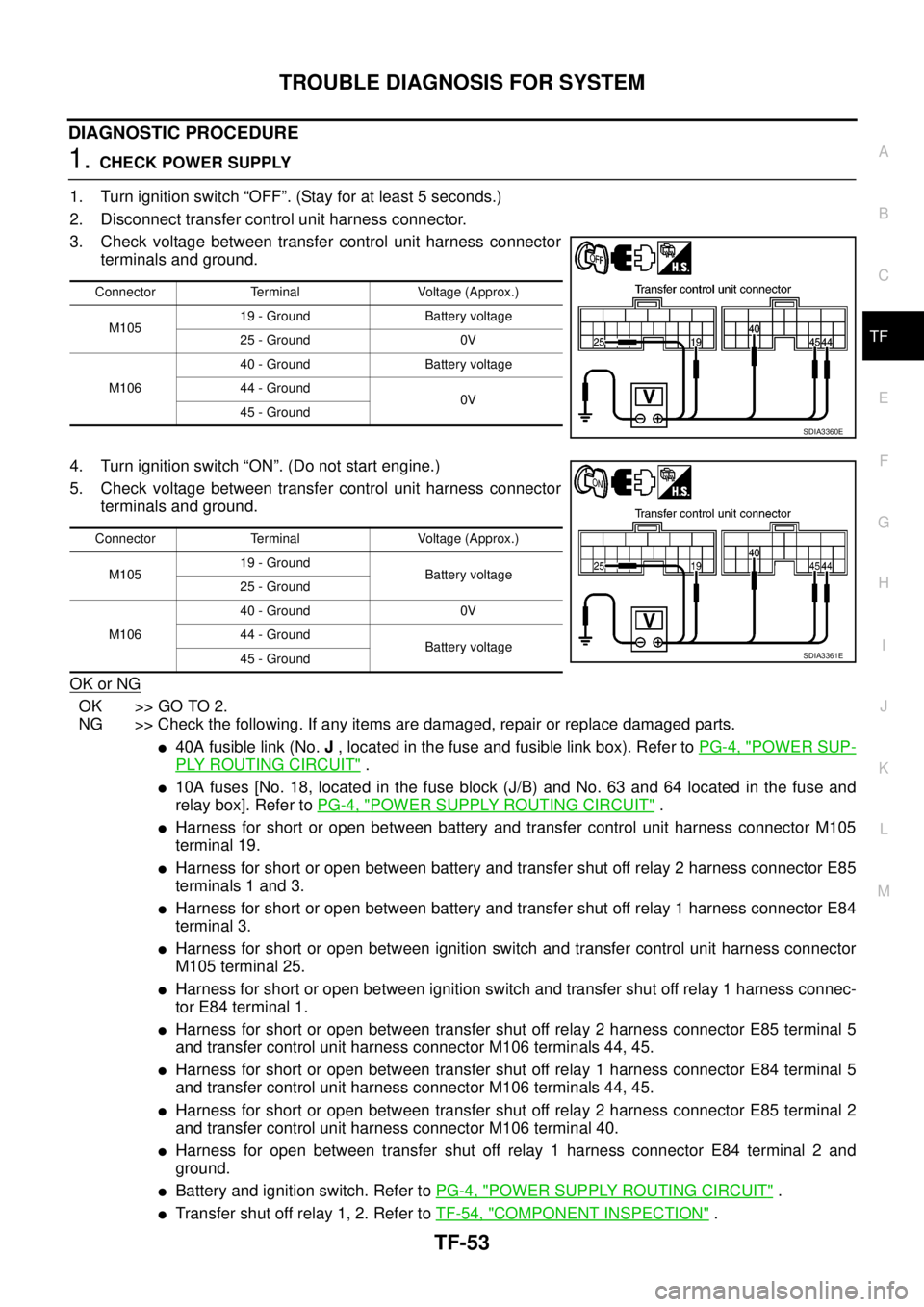
1. Turn ignition switch “OFF”. (Stay for at least 5 seconds.)
2. Disconnect transfer control unit harness connector.
3. Check voltage between transfer control unit harness connector
terminals and ground.
4. Turn ignition switch “ON”. (Do not start engine.)
5. Check voltage between transfer control unit harness connector
terminals and ground.
OK or NG
OK >> GO TO 2.
NG >> Check the following. If any items are damaged, repair or replace damaged parts.
l40A fusible link (No.J, located in the fuse and fusible link box). Refer toPG-4, "POWER SUP-
PLY ROUTING CIRCUIT".
l10A fuses [No. 18, located in the fuse block (J/B) and No. 63 and 64 located in the fuse and
relay box]. Refer toPG-4, "
POWER SUPPLY ROUTING CIRCUIT".
lHarness for short or open between battery and transfer control unit harness connector M105
terminal 19.
lHarness for short or open between battery and transfer shut off relay 2 harness connector E85
terminals 1 and 3.
lHarness for short or open between battery and transfer shut off relay 1 harness connector E84
terminal 3.
lHarness for short or open between ignition switch and transfer control unit harness connector
M105 terminal 25.
lHarness for short or open between ignition switch and transfer shut off relay 1 harness connec-
tor E84 terminal 1.
lHarness for short or open between transfer shut off relay 2 harness connector E85 terminal 5
and transfer control unit harness connector M106 terminals 44, 45.
lHarness for short or open between transfer shut off relay 1 harness connector E84 terminal 5
and transfer control unit harness connector M106 terminals 44, 45.
lHarness for short or open between transfer shut off relay 2 harness connector E85 terminal 2
and transfer control unit harness connector M106 terminal 40.
lHarness for open between transfer shut off relay 1 harness connector E84 terminal 2 and
ground.
lBattery and ignition switch. Refer toPG-4, "POWER SUPPLY ROUTING CIRCUIT".
lTransfer shut off relay 1, 2. Refer toTF-54, "COMPONENT INSPECTION".
Connector Terminal Voltage (Approx.)
M10519 - Ground Battery voltage
25 - Ground 0V
M10640 - Ground Battery voltage
44 - Ground
0V
45 - Ground
SDIA3360E
Connector Terminal Voltage (Approx.)
M10519 - Ground
Battery voltage
25 - Ground
M10640 - Ground 0V
44 - Ground
Battery voltage
45 - Ground
SDIA3361E
Page 3021 of 3171
TF-54
TROUBLE DIAGNOSIS FOR SYSTEM
2.CHECK GROUND CIRCUIT
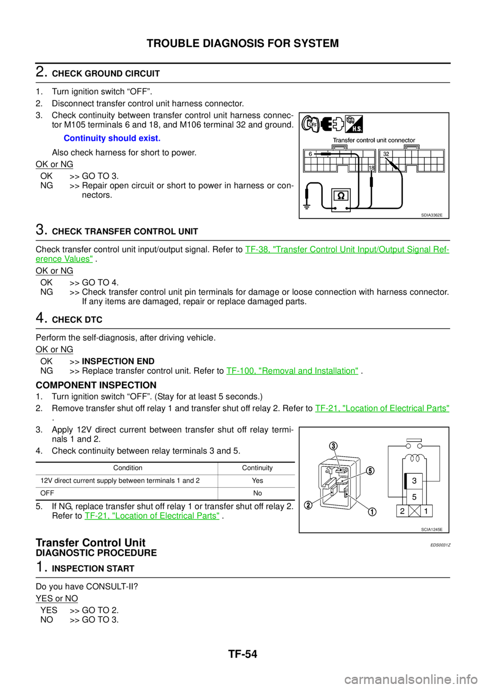
1. Turn ignition switch “OFF”.
2. Disconnect transfer control unit harness connector.
3. Check continuity between transfer control unit harness connec-
tor M105 terminals 6 and 18, and M106 terminal 32 and ground.
Also check harness for short to power.
OK or NG
OK >> GO TO 3.
NG >> Repair open circuit or short to power in harness or con-
nectors.
3.CHECK TRANSFER CONTROL UNIT
Check transfer control unit input/output signal. Refer toTF-38, "
Transfer Control Unit Input/Output Signal Ref-
erence Values".
OK or NG
OK >> GO TO 4.
NG >> Check transfer control unit pin terminals for damage or loose connection with harness connector.
If any items are damaged, repair or replace damaged parts.
4.CHECK DTC
Perform the self-diagnosis, after driving vehicle.
OK or NG
OK >>INSPECTION END
NG >> Replace transfer control unit. Refer toTF-100, "
Removal and Installation".
COMPONENT INSPECTION
1. Turn ignition switch “OFF”. (Stay for at least 5 seconds.)
2. Remove transfer shut off relay 1 and transfer shut off relay 2. Refer toTF-21, "
Location of Electrical Parts"
.
3. Apply 12V direct current between transfer shut off relay termi-
nals 1 and 2.
4. Check continuity between relay terminals 3 and 5.
5. If NG, replace transfer shut off relay 1 or transfer shut off relay 2.
Refer toTF-21, "
Location of Electrical Parts".
Transfer Control UnitEDS0031Z
DIAGNOSTIC PROCEDURE
1.INSPECTION START
Do you have CONSULT-II?
YESorNO
YES >> GO TO 2.
NO >> GO TO 3.Continuity should exist.
SDIA3362E
Condition Continuity
12V direct current supply between terminals 1 and 2 Yes
OFF No
SCIA1245E
Page 3022 of 3171
TROUBLE DIAGNOSIS FOR SYSTEM
TF-55
C
E
F
G
H
I
J
K
L
MA
B
TF
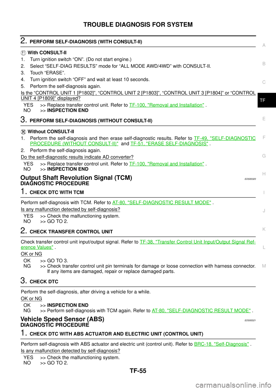
2.PERFORM SELF-DIAGNOSIS (WITH CONSULT-II)
With CONSULT-II
1. Turn ignition switch “ON”. (Do not start engine.)
2. Select “SELF-DIAG RESULTS” mode for “ALL MODE AWD/4WD” with CONSULT-II.
3. Touch “ERASE”.
4. Turn ignition switch “OFF” and wait at least 10 seconds.
5. Perform the self-diagnosis again.
Is the
“CONTROL UNIT 1 [P1802]”,“CONTROL UNIT 2 [P1803]”,“CONTROL UNIT 3 [P1804]”or“CONTROL
UNIT 4 [P1809]”displayed?
YES >> Replace transfer control unit. Refer toTF-100, "Removal and Installation".
NO >>INSPECTION END
3.PERFORM SELF-DIAGNOSIS (WITHOUT CONSULT-II)
Without CONSULT-II
1. Perform the self-diagnosis and then erase self-diagnostic results. Refer toTF-49, "
SELF-DIAGNOSTIC
PROCEDURE (WITHOUT CONSULT-II)"andTF-51, "ERASE SELF-DIAGNOSIS".
2. Perform the self-diagnosis again.
Do the self-diagnostic results indicate AD converter?
YES >> Replace transfer control unit. Refer toTF-100, "Removal and Installation".
NO >>INSPECTION END
Output Shaft Revolution Signal (TCM)EDS00320
DIAGNOSTIC PROCEDURE
1.CHECK DTC WITH TCM
Perform self-diagnosis with TCM. Refer toAT-80, "
SELF-DIAGNOSTIC RESULT MODE".
Is any malfunction detected by self-diagnosis?
YES >> Check the malfunctioning system.
NO >> GO TO 2.
2.CHECK TRANSFER CONTROL UNIT
Check transfer control unit input/output signal. Refer toTF-38, "
Transfer Control Unit Input/Output Signal Ref-
erence Values".
OK or NG
OK >> GO TO 3.
NG >> Check transfer control unit pin terminals for damage or loose connection with harness connector.
If any items are damaged, repair or replace damaged parts.
3.CHECK DTC
Perform the self-diagnosis, after driving a vehicle for a while.
OK or NG
OK >>INSPECTION END
NG >> Perform self-diagnosis with TCM again. Refer toAT-80, "
SELF-DIAGNOSTIC RESULT MODE".
Vehicle Speed Sensor (ABS)EDS00321
DIAGNOSTIC PROCEDURE
1.CHECK DTC WITH ABS ACTUATOR AND ELECTRIC UNIT (CONTROL UNIT)
Perform self-diagnosis with ABS actuator and electric unit (control unit). Refer toBRC-18, "
Self-Diagnosis".
Is any malfunction detected by self-diagnosis?
YES >> Check the malfunctioning system.
NO >> GO TO 2.
Page 3025 of 3171
TF-58
TROUBLE DIAGNOSIS FOR SYSTEM
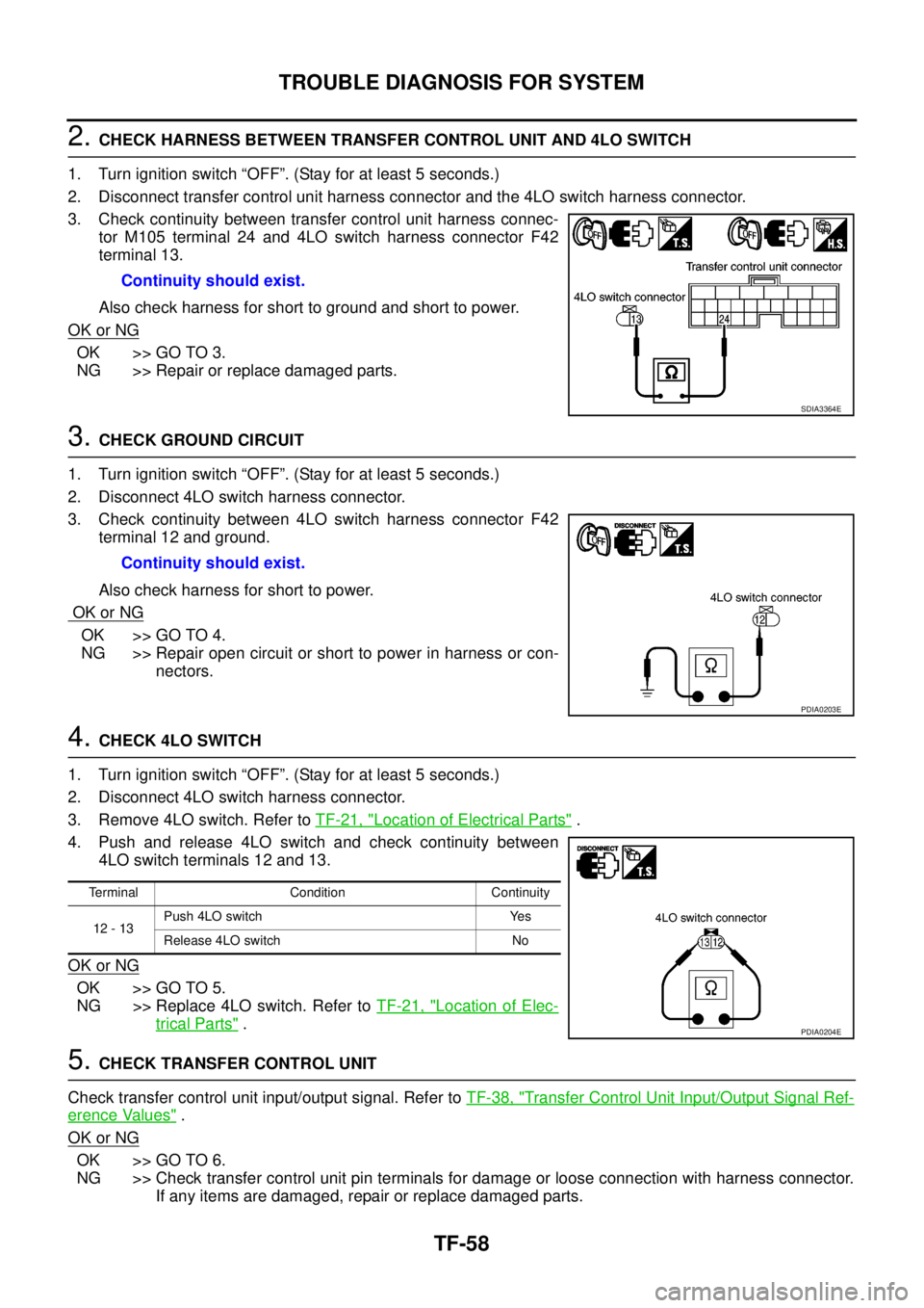
2.CHECK HARNESS BETWEEN TRANSFER CONTROL UNIT AND 4LO SWITCH
1. Turn ignition switch “OFF”. (Stay for at least 5 seconds.)
2. Disconnect transfer control unit harness connector and the 4LO switch harness connector.
3. Check continuity between transfer control unit harness connec-
tor M105 terminal 24 and 4LO switch harness connector F42
terminal 13.
Also check harness for short to ground and short to power.
OK or NG
OK >> GO TO 3.
NG >> Repair or replace damaged parts.
3.CHECK GROUND CIRCUIT
1. Turn ignition switch “OFF”. (Stay for at least 5 seconds.)
2. Disconnect 4LO switch harness connector.
3. Check continuity between 4LO switch harness connector F42
terminal 12 and ground.
Also check harness for short to power.
OK or NG
OK >> GO TO 4.
NG >> Repair open circuit or short to power in harness or con-
nectors.
4.CHECK 4LO SWITCH
1. Turn ignition switch “OFF”. (Stay for at least 5 seconds.)
2. Disconnect 4LO switch harness connector.
3. Remove 4LO switch. Refer toTF-21, "
Location of Electrical Parts".
4. Push and release 4LO switch and check continuity between
4LO switch terminals 12 and 13.
OK or NG
OK >> GO TO 5.
NG >> Replace 4LO switch. Refer toTF-21, "
Location of Elec-
trical Parts".
5.CHECK TRANSFER CONTROL UNIT
Check transfer control unit input/output signal. Refer toTF-38, "
Transfer Control Unit Input/Output Signal Ref-
erence Values".
OK or NG
OK >> GO TO 6.
NG >> Check transfer control unit pin terminals for damage or loose connection with harness connector.
If any items are damaged, repair or replace damaged parts. Continuity should exist.
SDIA3364E
Continuity should exist.
PDIA0203E
Terminal Condition Continuity
12 - 13Push 4LO switch Yes
Release 4LO switch No
PDIA0204E