Page 2933 of 3171
SRS-24
TROUBLE DIAGNOSIS
NOTE:
Follow the procedures in numerical order when repairing malfunctioning parts. Confirm whether malfunction is
eliminated using air bag warning lamp or CONSULT-II each time repair is finished. If malfunction is still
observed, proceed to the next step. When malfunction is eliminated, further repair work is not required.
DIAGNOSTIC PROCEDURE 3
Final Check of SRS Using CONSULT-II—Diagnosis Mode
CAUTION:
If CONSULT-II is used with no connection of CONSULT-II CONVERTER, malfunction might be detected
in self-diagnosis depending on control unit which carry out CAN communication.
1. After repairing SRS, connect both battery cables.
2. Connect CONSULT-II and CONSULT-II CONVERTER to data
link connector.
3. Turn ignition switch ON.
4. Touch “START (NISSAN BASED VHCL)”.
5. Touch “AIR BAG”.
If "AIR BAG" is not indicated, refer toGI-50, "
CONSULT-II Data
Link Connector (DLC) Circuit".
BBIA0538E
BCIA0029E
BCIA0030E
Page 2934 of 3171
![NISSAN NAVARA 2005 Repair Workshop Manual TROUBLE DIAGNOSIS
SRS-25
C
D
E
F
G
I
J
K
L
MA
B
SRS
6. Touch “SELF-DIAG [CURRENT]”.
7. If no malfunction is detected on “SELF-DIAG [CURRENT]”,
repair of SRS is completed. Go to step 8.
If any NISSAN NAVARA 2005 Repair Workshop Manual TROUBLE DIAGNOSIS
SRS-25
C
D
E
F
G
I
J
K
L
MA
B
SRS
6. Touch “SELF-DIAG [CURRENT]”.
7. If no malfunction is detected on “SELF-DIAG [CURRENT]”,
repair of SRS is completed. Go to step 8.
If any](/manual-img/5/57362/w960_57362-2933.png)
TROUBLE DIAGNOSIS
SRS-25
C
D
E
F
G
I
J
K
L
MA
B
SRS
6. Touch “SELF-DIAG [CURRENT]”.
7. If no malfunction is detected on “SELF-DIAG [CURRENT]”,
repair of SRS is completed. Go to step 8.
If any malfunction is detected on “SELF-DIAG [CURRENT]”, the
malfunctioning part is not repaired completely or another mal-
functioning part is detected. Go toSRS-20, "
DIAGNOSTIC
PROCEDURE 2", and repair malfunctioning part completely.
8. Touch “ERASE”.
NOTE:
Touch “ERASE” to clear the memory of the malfunction
(“SELF-DIAG [PAST]”).
If the memory of the malfunction in “SELF-DIAG [PAST]” is not
erased, the User mode shows the system malfunction by the
operation of the warning lamp even if the malfunction is repaired
completely.
9. Touch “BACK” key of CONSULT-II to “SELECT DIAG MODE”
screen. Touch “SELF-DIAG [PAST]”.
10. Check that no malfunction is detected on “SELF-DIAG [PAST]”.
11. Touch “BACK” key of CONSULT-II until “SELECT SYSTEM”
appears in order to return to User mode from Diagnosis mode.
12. Turn ignition switch OFF then turn off and disconnect CON-
SULT-II. GotoSRS-18, "
Checking SRS Operation Using“AIR
BAG”Warning Lamp—User Mode".
BCIA0031E
SRS701
WHIA0152E
BCIA0031E
SRS702
Page 2935 of 3171

SRS-26
TROUBLE DIAGNOSIS
DIAGNOSTIC PROCEDURE 4 (CONTINUED FROM DIAGNOSTIC PROCEDURE 2)
Check SRS Repair History
1.CONSIDER POSSIBILITY THAT SELF-DIAGNOSTIC RESULT WAS NOT ERASED AFTER REPAIR
Check repair history of the SRS.
Have any previous repairs been made to the SRS?
Yes >> Self-diagnostic result “SELF-DIAG [PAST]” (previously stored in the memory) might not be erased
after repair. Go toSRS-24, "
DIAGNOSTIC PROCEDURE 3".
No >> Go toSRS-20, "
DIAGNOSTIC PROCEDURE 2".
DIAGNOSTIC PROCEDURE 5
Check SRS Intermittent Malfunction Using CONSULT-II—Diagnosis Mode
CAUTION:
If CONSULT-II is used with no connection of CONSULT-II CONVERTER, malfunction might be detected
in self-diagnosis depending on control unit which carry out CAN communication.
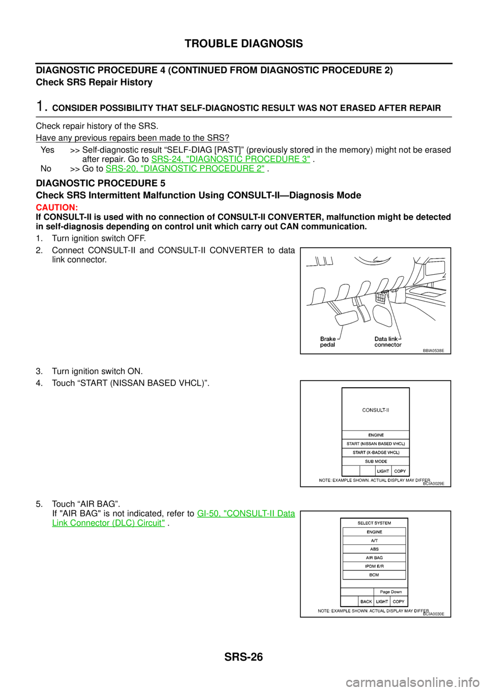
1. Turn ignition switch OFF.
2. Connect CONSULT-II and CONSULT-II CONVERTER to data
link connector.
3. Turn ignition switch ON.
4. Touch “START (NISSAN BASED VHCL)”.
5. Touch “AIR BAG”.
If "AIR BAG" is not indicated, refer toGI-50, "
CONSULT-II Data
Link Connector (DLC) Circuit".
BBIA0538E
BCIA0029E
BCIA0030E
Page 2936 of 3171
TROUBLE DIAGNOSIS
SRS-27
C
D
E
F
G
I
J
K
L
MA
B
SRS
6. Touch “SELF-DIAG [PAST]”.
7. If diagnostic codes are displayed on “SELF-DIAG [PAST]”, go to
step 10.
If no malfunction is detected on “SELF-DIAG [PAST]”, touch
“BACK” and go back to “SELECT DIAG MODE”.
8. Touch “TROUBLE DIAG RECORD”.
NOTE:
With “TROUBLE DIAG RECORD”, diagnosis results previ-
ously erased by a reset operation can be displayed.
9. Diagnostic code is displayed on “TROUBLE DIAG RECORD”.
10. Touch “PRINT”.
11. Compare diagnostic codes toSRS-28, "
CONSULT-II Diagnostic
Code Chart ("SELF-DIAG [PAST]" or "TROUBLE DIAG
RECORD")".
12. Touch “BACK” key of CONSULT-II until “SELECT SYSTEM”
appears.
13. Turn ignition switch OFF, and disconnect CONSULT-II, and both
battery cables.
BCIA0031E
WHIA0152E
SRS702
BCIA0031E
WHIA0153E
Page 2939 of 3171

SRS-30
TROUBLE DIAGNOSIS
Trouble Diagnosis Without CONSULT-II
EHS001XP
DIAGNOSTIC PROCEDURE 6
Inspect SRS Malfunction Using "AIR BAG" Warning Lamp—Diagnosis Mode
NOTE:
SRS will not enter Diagnosis mode if no malfunction is detected in User mode.
1. Turn ignition switch ON.
2. After “AIR BAG” warning lamp lights for 7 seconds, turn ignition switch OFF within 1 second.
3. Wait more than 3 seconds.
4. Repeat steps 1 to 3 two more times (3 times total).
5. Turn ignition switch ON.
SRS is now in Diagnosis mode.
"AIR BAG" warning lamp operates in Diagnosis mode as follows:
CURTAIN MODULE LH
[OPEN]
[B1150]lThe circuit for LH side curtain air bag module is open. 1. Visually check the wiring harness
connection.
2. Replace the harness if it has visible
damage.
3. Replace LH side curtain air bag
module.
(Before disposal, it must be
deployed.)
4. Replace the air bag diagnosis sen-
sor unit.
5. Replace the related harness. CURTAIN MODULE LH
[VB-SHORT]
[B1151]
lThe circuit for LH side curtain air bag module is shorted to
some power supply circuits.
CURTAIN MODULE LH
[GND-SHORT]
[B1152]
lThe circuit for LH side curtain air bag module is shorted to
ground.
CURTAIN MODULE LH
[SHORT]
[B1153]
lThe circuits for the LH side curtain air bag module are
shorted to each other.
CURTAIN MODULE RH
[OPEN]
[B1145]
lThe circuit for RH side curtain air bag module is open. 1. Visually check the wiring harness
connection.
2. Replace the harness if it has visible
damage.
3. Replace RH side curtain air bag
module.
(Before disposal, it must be
deployed.)
4. Replace the air bag diagnosis sen-
sor unit.
5. Replace the related harness. CURTAIN MODULE RH
[VB-SHORT]
[B1146]
lThe circuit for RH side curtain air bag module is shorted to
some power supply circuits.
CURTAIN MODULE RH
[GND-SHORT]
[B1147]
lThe circuit for RH side curtain air bag module is shorted to
ground.
CURTAIN MODULE RH
[SHORT]
[B1148]
lThe circuits for the RH side curtain air bag module are
shorted to each other.
CONTROL UNIT
[B1XXX]
lAir bag diagnosis sensor unit is malfunctioning. 1. Visually check the wiring harness
connection.
2. Replace the harness if it has visible
damage.
3. Replace the air bag diagnosis sen-
sor unit. Diagnostic item ExplanationRepair order
Recheck SRS at each replacement
Page 2943 of 3171

SRS-34
TROUBLE DIAGNOSIS
Trouble Diagnosis: “AIR BAG” Warning Lamp Does Not Turn OFF
EHS001XQ
DIAGNOSTIC PROCEDURE 7
1.CHECK CONDITION OF AIR BAG MODULES
Inspect for any deployed air bag modules or seat belt pre-tensioners.
Are any air bag modules or seat belt pre-tensioners deployed?
Yes >> Refer toSRS-56, "COLLISION DIAGNOSIS".
No >> GO TO 2.
2.CHECK THE AIR BAG FUSE
Check 10A fuse [No. 13, located in the fuse block (J/B)].
Refer toPG-4, "
POWER SUPPLY ROUTING CIRCUIT".
OK or NG
OK >> GO TO 4.
NG >> GO TO 3.
3.CHECK AIR BAG FUSE AGAIN
Replace 10A fuse [No. 13, located in the fuse block (J/B)] and turn ignition switch ON.
Does the fuse blow again?
Yes >> Repair or replace main harness.
No >> Inspection End.
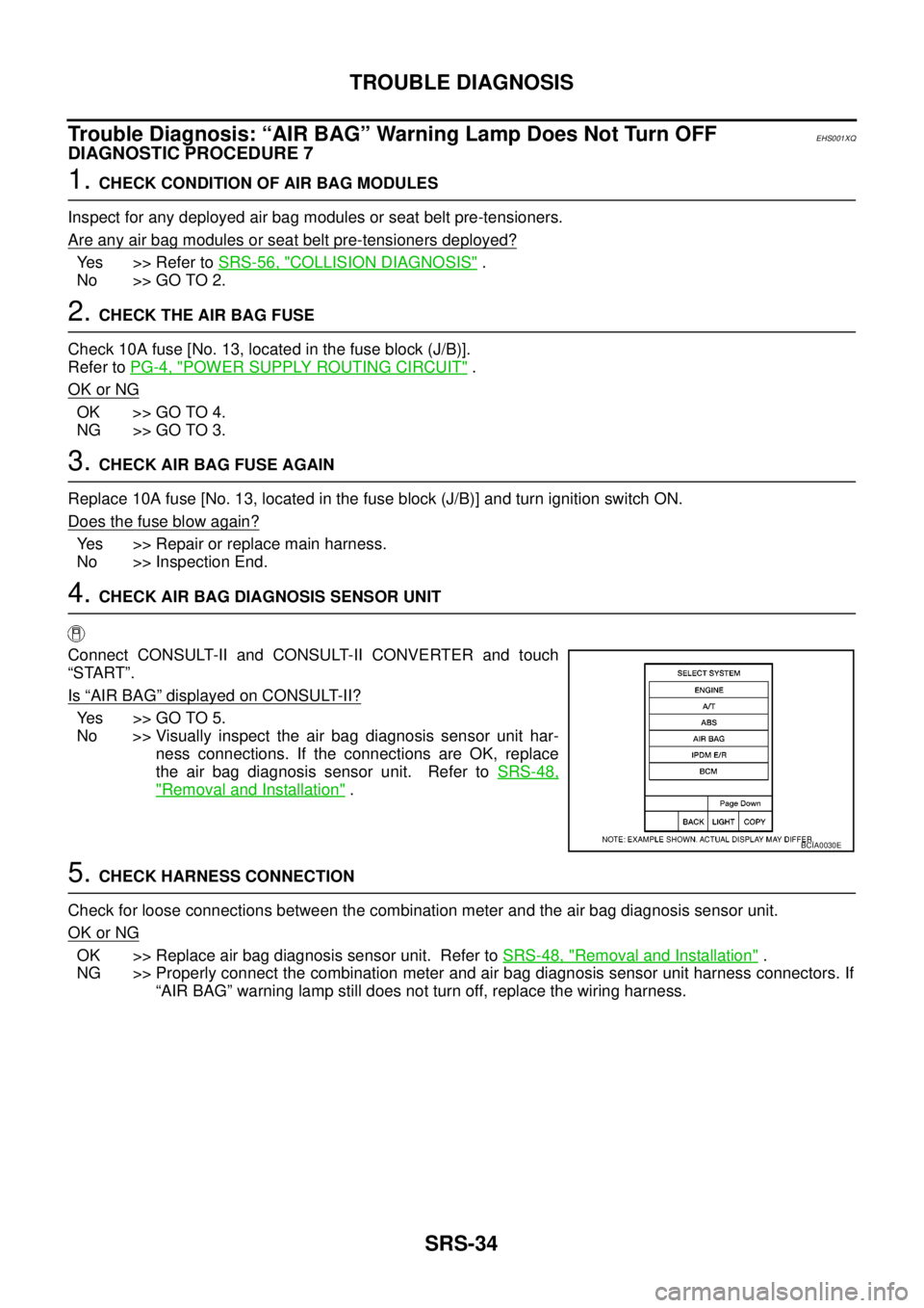
4.CHECK AIR BAG DIAGNOSIS SENSOR UNIT
Connect CONSULT-II and CONSULT-II CONVERTER and touch
“START”.
Is
“AIR BAG”displayed on CONSULT-II?
Yes >>GOTO5.
No >> Visually inspect the air bag diagnosis sensor unit har-
ness connections. If the connections are OK, replace
the air bag diagnosis sensor unit. Refer toSRS-48,
"Removal and Installation".
5.CHECK HARNESS CONNECTION
Check for loose connections between the combination meter and the air bag diagnosis sensor unit.
OK or NG
OK >> Replace air bag diagnosis sensor unit. Refer toSRS-48, "Removal and Installation".
NG >> Properly connect the combination meter and air bag diagnosis sensor unit harness connectors. If
“AIR BAG” warning lamp still does not turn off, replace the wiring harness.
BCIA0030E
Page 2944 of 3171
TROUBLE DIAGNOSIS
SRS-35
C
D
E
F
G
I
J
K
L
MA
B
SRS
Trouble Diagnosis: “AIR BAG” Warning Lamp Does Not Turn ONEHS001XR
DIAGNOSTIC PROCEDURE 8
1.CHECK METER FUSE
Check the 10A fuse [No. 14, located in the fuse block (J/B)].
Refer toPG-4, "
POWER SUPPLY ROUTING CIRCUIT".
OK or NG
OK >> GO TO 3.
NG >> GO TO 2.
2.CHECK METER FUSE AGAIN
Replace 10A fuse [No. 14, located in the fuse block (J/B)] and turn ignition switch ON.
Does the fuse blow again?
Yes >> Repair or replace the related harness.
No >> Inspection End.
3.CHECK HARNESS CONNECTION BETWEEN AIR BAG DIAGNOSIS SENSOR UNIT AND COMBINA-
TION METER
Disconnect the air bag diagnosis sensor unit harness connectors and turn ignition switch ON.
Does
“AIR BAG”warninglampturnON?
Yes >> Replace the air bag diagnosis sensor unit. Refer toSRS-48, "Removal and Installation".
No >> Check the combination meter power supply circuits and ground circuits. If OK, replace combina-
tion meter.
Page 2945 of 3171
SRS-36
DRIVER AIR BAG MODULE
DRIVER AIR BAG MODULE
PFP:K8510
Removal and InstallationEHS001XS
REMOVAL
CAUTION:
lDo not attempt to repair or replace damaged direct-connect SRS component connectors. If a
driver air bag direct-connect harness connector is damaged, the spiral cable must be replaced.
lBefore servicing the SRS, turn ignition switch OFF, disconnect both battery cables and wait at
least 3 minutes.
lWhen servicing the SRS, do not work from directly in front of air bag module.
1. Locate retaining clip access hole and insert screwdriver.
2. Press upward (toward center of steering wheel) on retaining clip until driver air bag module is released
from steering wheel.
3. Lift the driver air bag module from the steering wheel.
1. Steering wheel 2. Retaining clip 3. Driver air bag module connector
4. Driver air bag module 5. Retaining clip access hole 6. Horn connector
MHIB0099E
LHIA0085E