Page 224 of 3171
AT-216
KEY INTERLOCK CABLE
KEY INTERLOCK CABLE
PFP:34908
Removal and InstallationECS00G33
COMPONENTS
CAUTION:
lInstall key interlock cable in such a way that it will not be damaged by sharp bends, twists or inter-
ference with adjacent parts.
lAfter installing key interlock cable to control device, make sure that casing cap and bracket are
firmly secured in their positions. If casing cap can be removed with an external load of less than
39 N (4.0 kg, 8.8 lb), replace key interlock cable with new one.
SCIA6791E
Page 225 of 3171

KEY INTERLOCK CABLE
AT-217
D
E
F
G
H
I
J
K
L
MA
B
AT
REMOVAL
1. Remove center console. Refer toIP-16, "CENTER CONSOLE".
2. Remove lower instrument panel LH (for LHD models) or lower instrument panel RH (for RHD models) and
cluster lid A. Refer toIP-13, "
LOWER INSTRUMENT PANEL LH",IP-15, "LOWER INSTRUMENT
PANEL RH AND GLOVE BOX",IP-10, "INSTRUMENT PANEL".
3. Unlock slider by squeezing lock tabs on slider from adjuster
holder.
4. Remove casing cap from bracket of control device assembly
and remove interlock rod from adjuster holder.
5. Remove holder from key cylinder and remove key interlock
cable.
INSTALLATION
1. Set key interlock cable to key cylinder and install holder.
2. Turn ignition key to lock position.
3. Set selector lever to “P” position.
4. Insert interlock rod into adjuster holder.
5. Install casing cap to bracket.
6. Move slider in order to secure adjuster holder to interlock rod.
CAUTION:
Do not touch any other areas than slider or apply any force
to slider except in the sliding direction.
7. Install lower instrument panel LH (for LHD models) or lower
instrument panel RH (for RHD models) and cluster lid A. Refer
toIP-13, "
LOWER INSTRUMENT PANEL LH",IP-15, "LOWER
INSTRUMENT PANEL RH AND GLOVE BOX",IP-10,
"INSTRUMENT PANEL".
8. Install center console. Refer toIP-16, "
CENTER CONSOLE".
SCIA6793E
SCIA6900E
SCIA6900E
SCIA1232E
Page 247 of 3171

ON-VEHICLE SERVICE
AT-239
D
E
F
G
H
I
J
K
L
MA
B
AT
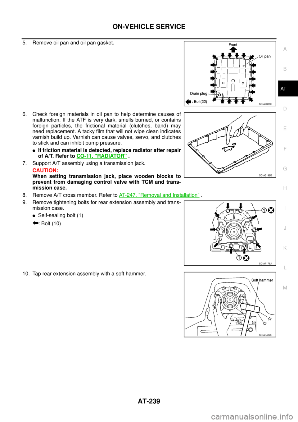
5. Remove oil pan and oil pan gasket.
6. Check foreign materials in oil pan to help determine causes of
malfunction. If the ATF is very dark, smells burned, or contains
foreign particles, the frictional material (clutches, band) may
need replacement. A tacky film that will not wipe clean indicates
varnish build up. Varnish can cause valves, servo, and clutches
to stick and can inhibit pump pressure.
lIf friction material is detected, replace radiator after repair
of A/T. Refer toCO-11, "
RADIATOR".
7. Support A/T assembly using a transmission jack.
CAUTION:
When setting transmission jack, place wooden blocks to
prevent from damaging control valve with TCM and trans-
mission case.
8. Remove A/T cross member. Refer toAT- 2 4 7 , "
Removal and Installation".
9. Remove tightening bolts for rear extension assembly and trans-
mission case.
lSelf-sealing bolt (1)
: Bolt (10)
10. Tap rear extension assembly with a soft hammer.
SCIA2308E
SCIA5199E
SCIA7176J
SCIA3432E
Page 251 of 3171

AIR BREATHER HOSE
AT-243
D
E
F
G
H
I
J
K
L
MA
B
AT
AIR BREATHER HOSEPFP:31098
Removal and InstallationECS00GVO
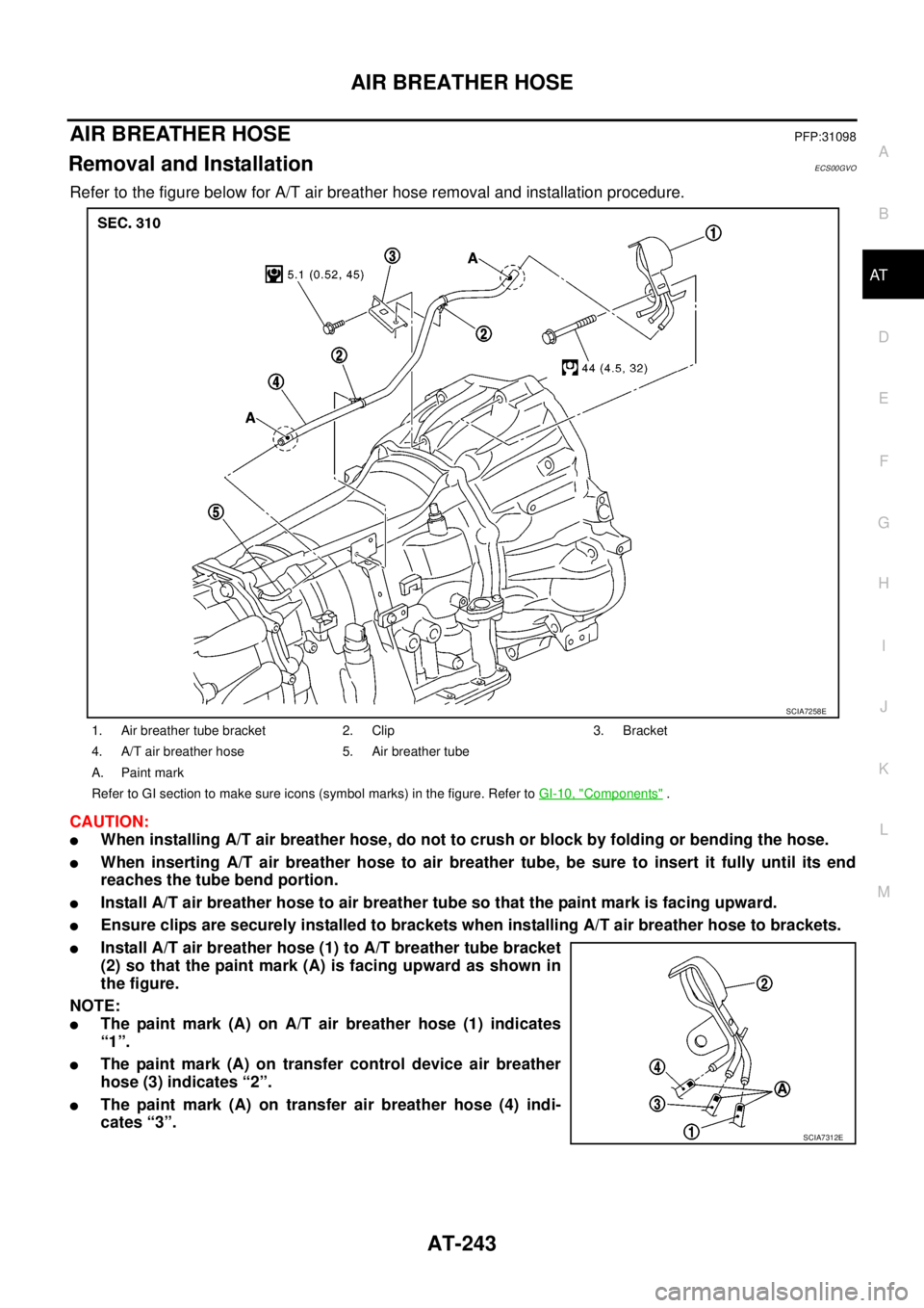
Refer to the figure below for A/T air breather hose removal and installation procedure.
CAUTION:
lWhen installing A/T air breather hose, do not to crush or block by folding or bending the hose.
lWhen inserting A/T air breather hose to air breather tube, be sure to insert it fully until its end
reaches the tube bend portion.
lInstall A/T air breather hose to air breather tube so that the paint mark is facing upward.
lEnsure clips are securely installed to brackets when installing A/T air breather hose to brackets.
lInstall A/T air breather hose (1) to A/T breather tube bracket
(2) so that the paint mark (A) is facing upward as shown in
the figure.
NOTE:
lThe paint mark (A) on A/T air breather hose (1) indicates
“1”.
lThe paint mark (A) on transfer control device air breather
hose (3) indicates “2”.
lThe paint mark (A) on transfer air breather hose (4) indi-
cates “3”.
1. Air breather tube bracket 2. Clip 3. Bracket
4. A/T air breather hose 5. Air breather tube
A. Paint mark
Refer to GI section to make sure icons (symbol marks) in the figure. Refer toGI-10, "
Components".
SCIA7258E
SCIA7312E
Page 257 of 3171

TRANSMISSION ASSEMBLY
AT-249
D
E
F
G
H
I
J
K
L
MA
B
AT
5. Remove front valance center, engine undercover front, engine under cover middle and engine under
coverrear.RefertoEI-15, "
FRONT BUMPER".
6. Remove front cross member.
7. Remove main muffler. Refer toEX-2, "
EXHAUST SYSTEM".
8. Remove rear propeller shaft. Refer toPR-8, "
Removal and Installation".
9. Remove front propeller shaft. Refer toPR-4, "
Removal and Installation".
10. Remove starter motor. Refer toSC-31, "
Removal and Installation".
11. Remove control cable and bracket. Refer toAT- 2 1 0 , "
Control Cable Removal and Installation".
12. Disconnect fluid cooler tube.
13. Remove A/T fluid charging pipe from A/T assembly.
14. Remove O-ring from A/T fluid charging pipe.
15. Plug up openings such as A/T fluid charging pipe hole, etc.
16. Remove rear plate cover from rear plate.
17. Turn crankshaft to access and remove the four bolts for drive
plate and torque converter.
CAUTION:
When turning crankshaft, turn it clockwise as viewed from
the front of engine.
18. Support A/T assembly using a transmission jack.
CAUTION:
When setting transmission jack, be careful not to allow it to
collide against drain plug.
19. Remove protector (fuel tube), and then disconnect fuel tubes.
Refer toFL-7, "
FUEL COOLER". (4WD models)
20. Remove A/T cross member.
21. Remove engine mounting insulator (rear) from A/T assembly.
22. Disconnect the following:
lA/T assembly harness connector
lATP switch connector
l4LO switch connector
lWait detection switch connector
lTransfer control device connector
23. Support transfer assembly using a transmission jack. (4WD models)
24. Remove the wiring harness from bracket.
25. Remove bolts fixing A/T assembly to engine assembly.
26. Remove A/T assembly from the vehicle.
CAUTION:
lSecure torque converter to prevent it from dropping.
lSecure A/T assembly to a transmission jack.
27. Remove A/T air breather hose. Refer toAT- 2 4 3 , "
AIR
BREATHER HOSE".
28. Remove transfer assembly from A/T assembly. Refer toT F - 111 ,
"Removal and Installation". (4WD models)
SCIA6828E
SCIA6927E
SCIA2203E
Page 258 of 3171

AT-250
TRANSMISSION ASSEMBLY
INSPECTION
Installation and Inspection of Torque Converter
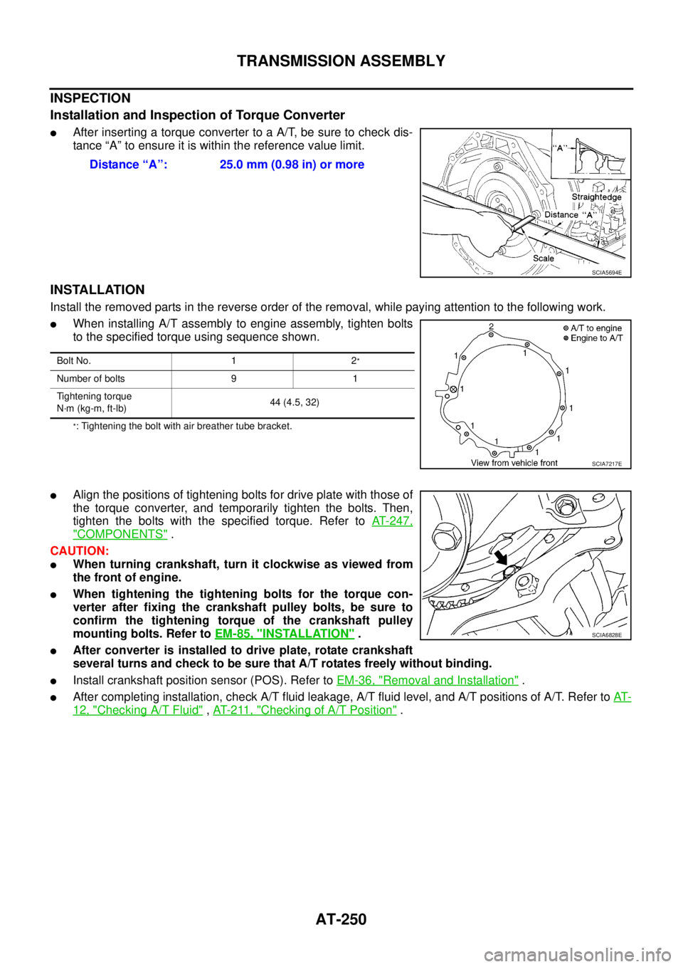
lAfter inserting a torque converter to a A/T, be sure to check dis-
tance “A” to ensure it is within the reference value limit.
INSTALLATION
Install the removed parts in the reverse order of the removal, while paying attention to the following work.
lWhen installing A/T assembly to engine assembly, tighten bolts
to the specified torque using sequence shown.
*: Tightening the bolt with air breather tube bracket.
lAlign the positions of tightening bolts for drive plate with those of
the torque converter, and temporarily tighten the bolts. Then,
tighten the bolts with the specified torque. Refer toAT-247,
"COMPONENTS".
CAUTION:
lWhen turning crankshaft, turn it clockwise as viewed from
the front of engine.
lWhen tightening the tightening bolts for the torque con-
verter after fixing the crankshaft pulley bolts, be sure to
confirm the tightening torque of the crankshaft pulley
mounting bolts. Refer toEM-85, "
INSTALLATION".
lAfter converter is installed to drive plate, rotate crankshaft
several turns and check to be sure that A/T rotates freely without binding.
lInstall crankshaft position sensor (POS). Refer toEM-36, "Removal and Installation".
lAfter completing installation, check A/T fluid leakage, A/T fluid level, and A/T positions of A/T. Refer toAT-
12, "Checking A/T Fluid",AT- 2 11 , "Checking of A/T Position". Distance “A”: 25.0 mm (0.98 in) or more
SCIA5694E
Bolt No. 1 2*
Number of bolts 9 1
Tightening torque
N·m (kg-m, ft-lb)44 (4.5, 32)
SCIA7217E
SCIA6828E
Page 271 of 3171
DISASSEMBLY
AT-263
D
E
F
G
H
I
J
K
L
MA
B
AT
DISASSEMBLYPFP:31020
DisassemblyECS00G3E
CAUTION:
Do not disassemble parts behind drum support. Refer toAT-14, "
Cross-Sectional View (2WD Models)"
,AT-15, "Cross-Sectional View (4WD Models)".
1. Drain ATF through drain hole.
2. Remove torque converter by holding it firmly and turing while
pulling straight out.
3. Check torque converter one-way clutch using a check tool as
showninthefigure.
a. Insert a check tool into the groove of bearing support built into
one-way clutch outer race.
b. When fixing bearing support with a check tool, rotate one-way
clutch spline using a screwdriver.
c. Make sure that inner race rotates clockwise only. If not, replace
torque converter assembly.
4. Remove converter housing from transmission case.
CAUTION:
Be careful not to scratch converter housing.
SCIA5010E
SCIA3171E
SCIA5171E
Page 274 of 3171
AT-266
DISASSEMBLY
14. Loosen lock nut and remove band servo anchor end pin from
transmission case.
15. Remove brake band from transmission case.
lTo prevent brake linings from cracking or peeling, do not
stretch the flexible band unnecessarily. When removing
brake band, always secure it with a clip as shown in the
figure at right.
Leave the clip in position after removing the brake band.
lCheck brake band facing for damage, cracks, wear or
burns.
16. Remove mid carrier assembly and rear carrier assembly as a
unit.
17. Remove mid carrier assembly from rear carrier assembly.
SCIA6512E
SCIA2580E
SAT655
SCIA5017E
SCIA5174E