2005 NISSAN NAVARA lock
[x] Cancel search: lockPage 392 of 3171
ATC-58
TROUBLE DIAGNOSIS
CHECKING DISCHARGE AIR
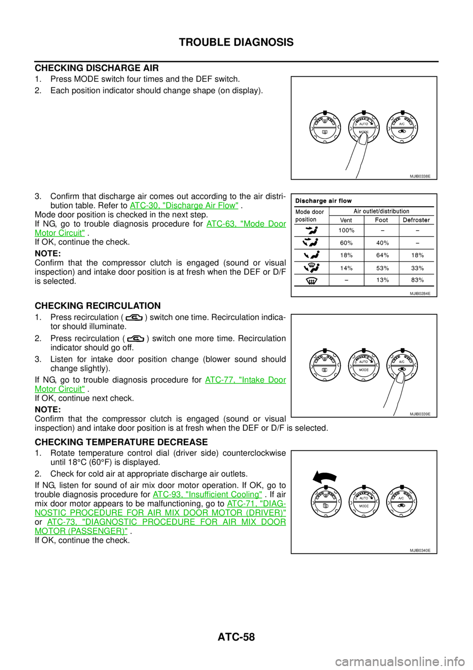
1. Press MODE switch four times and the DEF switch.
2. Each position indicator should change shape (on display).
3. Confirm that discharge air comes out according to the air distri-
bution table. Refer toAT C - 3 0 , "
Discharge Air Flow".
Mode door position is checked in the next step.
If NG, go to trouble diagnosis procedure forAT C - 6 3 , "
Mode Door
Motor Circuit".
If OK, continue the check.
NOTE:
Confirm that the compressor clutch is engaged (sound or visual
inspection) and intake door position is at fresh when the DEF or D/F
is selected.
CHECKING RECIRCULATION
1. Press recirculation ( ) switch one time. Recirculation indica-
tor should illuminate.
2. Press recirculation ( ) switch one more time. Recirculation
indicator should go off.
3. Listen for intake door position change (blower sound should
change slightly).
If NG, go to trouble diagnosis procedure forAT C - 7 7 , "
Intake Door
Motor Circuit".
If OK, continue next check.
NOTE:
Confirm that the compressor clutch is engaged (sound or visual
inspection) and intake door position is at fresh when the DEF or D/F is selected.
CHECKING TEMPERATURE DECREASE
1. Rotate temperature control dial (driver side) counterclockwise
until 18°C(60°F) is displayed.
2. Check for cold air at appropriate discharge air outlets.
If NG, listen for sound of air mix door motor operation. If OK, go to
trouble diagnosis procedure forAT C - 9 3 , "
Insufficient Cooling".Ifair
mix door motor appears to be malfunctioning, go toAT C - 7 1 , "
DIAG-
NOSTIC PROCEDURE FOR AIR MIX DOOR MOTOR (DRIVER)"
orAT C - 7 3 , "DIAGNOSTIC PROCEDURE FOR AIR MIX DOOR
MOTOR (PASSENGER)".
If OK, continue the check.
MJIB0338E
MJIB0284E
MJIB0339E
MJIB0340E
Page 393 of 3171

TROUBLE DIAGNOSIS
ATC-59
C
D
E
F
G
H
I
K
L
MA
B
AT C
CHECKING TEMPERATURE INCREASE
1. Rotate temperature control dial clockwise (driver side) until 32°C
(90°F) is displayed.
2. Check for hot air at appropriate discharge air outlets.
If NG, listen for sound of air mix door motor operation. If OK, go to
trouble diagnosis procedure forATC-100, "
Insufficient Heating".If
air mix door motor appears to be malfunctioning, go toAT C - 7 1 ,
"DIAGNOSTIC PROCEDURE FOR AIR MIX DOOR MOTOR
(DRIVER)".
If OK, continue with next check.
CHECK A/C SWITCH
1. Press A/C switch when AUTO switch is ON, or in manual mode.
2. A/C switch indicator will turn ON.
lConfirm that the compressor clutch engages (sound or visual
inspection).
If NG, go to trouble diagnosis procedure forAT C - 8 7 , "
Magnet Clutch
Circuit".
If OK, continue with next check.
CHECKING AUTO MODE
1. Press AUTO switch.
2. Display should indicate AUTO.
lIf ambient temperature is warm, and selected temperature is
cool, confirm that the compressor clutch engages (sound or
visual inspection). (Discharge air and blower speed will
depend on ambient, in-vehicle, and set temperatures.)
If NG, go to trouble diagnosis procedure forAT C - 6 0 , "
Power Supply
and Ground Circuit for Front Air Control", then if necessary, trouble
diagnosis procedure forAT C - 8 7 , "
Magnet Clutch Circuit".
If all operational checks are OK (symptom cannot be duplicated), go
to malfunction simulation tests inAT C - 3 5 , "
How to Perform Trouble
Diagnosis for Quick and Accurate Repair"and perform tests as out-
lined to simulate driving conditions environment. If symptom appears, refer toAT C - 3 5 , "
How to Perform Trou-
ble Diagnosis for Quick and Accurate Repair",AT C - 3 5 , "SYMPTOM TABLE"and perform applicable trouble
diagnosis procedures.
MJIB0341E
MJIB0342E
MJIB0336E
Page 396 of 3171
ATC-62
TROUBLE DIAGNOSIS
1.CHECK POWER SUPPLY CIRCUITS FOR FRONT AIR CONTROL
1. Turn ignition switch OFF.
2. Disconnect front air control connector.
3. Turn ignition switch ON.
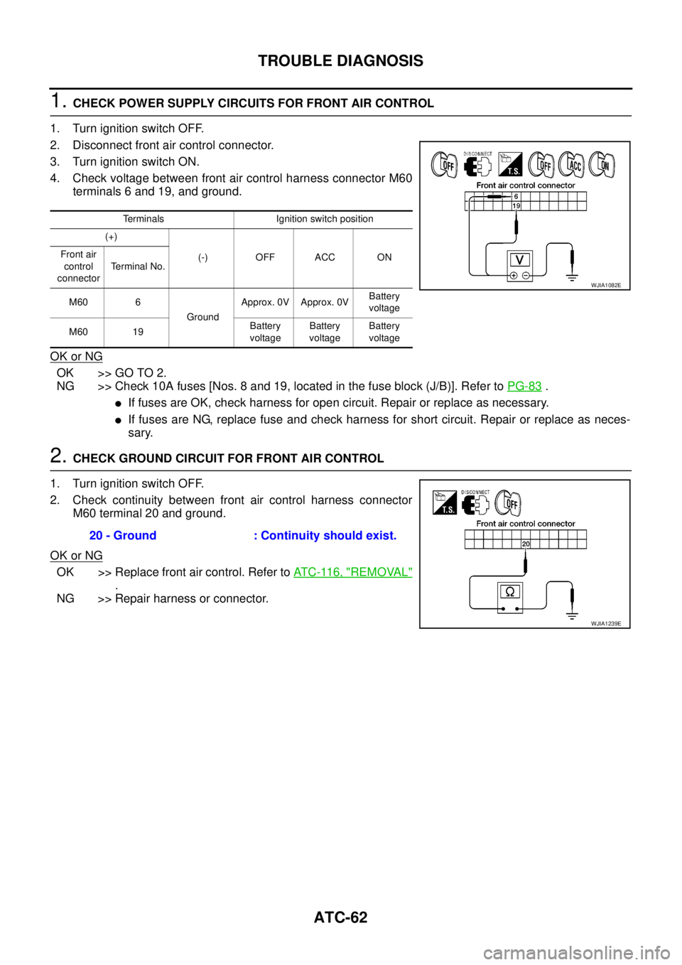
4. Check voltage between front air control harness connector M60
terminals 6 and 19, and ground.
OK or NG
OK >> GO TO 2.
NG >> Check 10A fuses [Nos. 8 and 19, located in the fuse block (J/B)]. Refer toPG-83
.
lIf fuses are OK, check harness for open circuit. Repair or replace as necessary.
lIf fuses are NG, replace fuse and check harness for short circuit. Repair or replace as neces-
sary.
2.CHECK GROUND CIRCUIT FOR FRONT AIR CONTROL
1. Turn ignition switch OFF.
2. Check continuity between front air control harness connector
M60 terminal 20 and ground.
OK or NG
OK >> Replace front air control. Refer toAT C - 11 6 , "REMOVAL"
.
NG >> Repair harness or connector.
Terminals Ignition switch position
(+)
(-) OFF ACC ON Front air
control
connectorTerminal No.
M60 6
GroundApprox. 0V Approx. 0VBattery
voltage
M60 19Battery
voltageBattery
voltageBattery
voltage
WJIA1082E
20 - Ground : Continuity should exist.
WJIA1239E
Page 433 of 3171
TROUBLE DIAGNOSIS
ATC-99
C
D
E
F
G
H
I
K
L
MA
B
AT C
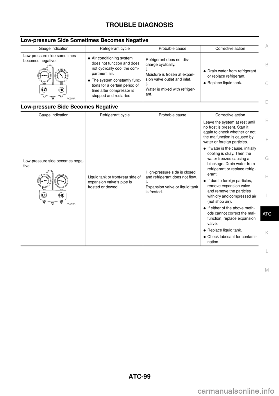
Low-pressure Side Sometimes Becomes Negative
Low-pressure Side Becomes Negative
Gauge indication Refrigerant cycle Probable cause Corrective action
Low-pressure side sometimes
becomes negative.
lAir conditioning system
does not function and does
not cyclically cool the com-
partment air.
lThe system constantly func-
tions for a certain period of
time after compressor is
stopped and restarted.Refrigerant does not dis-
charge cyclically.
¯
Moisture is frozen at expan-
sion valve outlet and inlet.
¯
Water is mixed with refriger-
ant.
lDrain water from refrigerant
or replace refrigerant.
lReplace liquid tank.
AC354A
Gauge indication Refrigerant cycle Probable cause Corrective action
Low-pressure side becomes nega-
tive.
Liquid tank or front/rear side of
expansion valve¢spipeis
frosted or dewed.High-pressure side is closed
and refrigerant does not flow.
¯
Expansion valve or liquid tank
is frosted.Leave the system at rest until
no frost is present. Start it
again to check whether or not
the malfunction is caused by
water or foreign particles.
lIf water is the cause, initially
cooling is okay. Then the
water freezes causing a
blockage. Drain water from
refrigerant or replace refrig-
erant.
lIf due to foreign particles,
remove expansion valve
and remove the particles
with dry and compressed air
(not shop air).
lIf either of the above meth-
ods cannot correct the mal-
function, replace expansion
valve.
lReplace liquid tank.
lCheck lubricant for contami-
nation.
AC362A
Page 460 of 3171
ATC-126
HEATER & COOLING UNIT ASSEMBLY
Removal and Installation
EJS006C9
REMOVAL
1. Discharge the refrigerant from the A/C system. Refer toATC-138, "Discharging Refrigerant".
2. Drain the coolant from the engine cooling system. Refer toCO-8, "
DRAINING ENGINE COOLANT".
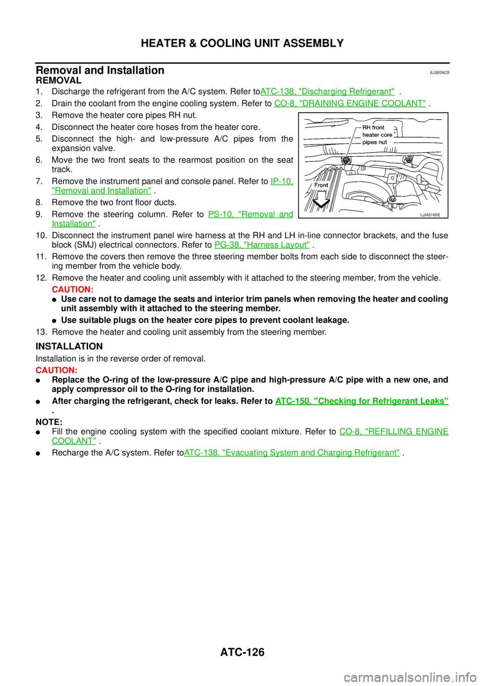
3. Remove the heater core pipes RH nut.
4. Disconnect the heater core hoses from the heater core.
5. Disconnect the high- and low-pressure A/C pipes from the
expansion valve.
6. Move the two front seats to the rearmost position on the seat
track.
7. Remove the instrument panel and console panel. Refer toIP-10,
"Removal and Installation".
8. Remove the two front floor ducts.
9. Remove the steering column. Refer toPS-10, "
Removal and
Installation".
10. Disconnect the instrument panel wire harness at the RH and LH in-line connector brackets, and the fuse
block (SMJ) electrical connectors. Refer toPG-38, "
Harness Layout".
11. Remove the covers then remove the three steering member bolts from each side to disconnect the steer-
ing member from the vehicle body.
12. Remove the heater and cooling unit assembly with it attached to the steering member, from the vehicle.
CAUTION:
lUse care not to damage the seats and interior trim panels when removing the heater and cooling
unit assembly with it attached to the steering member.
lUse suitable plugs on the heater core pipes to prevent coolant leakage.
13. Remove the heater and cooling unit assembly from the steering member.
INSTALLATION
Installation is in the reverse order of removal.
CAUTION:
lReplace the O-ring of the low-pressure A/C pipe and high-pressure A/C pipe with a new one, and
apply compressor oil to the O-ring for installation.
lAfter charging the refrigerant, check for leaks. Refer toATC-150, "Checking for Refrigerant Leaks"
.
NOTE:
lFill the engine cooling system with the specified coolant mixture. Refer toCO-8, "REFILLING ENGINE
COOLANT".
lRecharge the A/C system. Refer toATC-138, "Evacuating System and Charging Refrigerant".
LJIA0165E
Page 476 of 3171
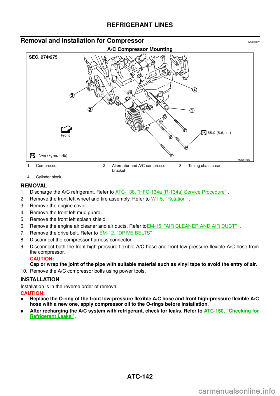
ATC-142
REFRIGERANT LINES
Removal and Installation for Compressor
EJS006CN
A/C Compressor Mounting
REMOVAL
1. Discharge the A/C refrigerant. Refer toATC-138, "HFC-134a (R-134a) Service Procedure".
2. Remove the front left wheel and tire assembly. Refer toWT-5, "
Rotation".
3. Remove the engine cover.
4. Remove the front left mud guard.
5. Remove the front left splash shield.
6. Remove the engine air cleaner and air ducts. Refer toEM-15, "
AIR CLEANER AND AIR DUCT".
7. Remove the drive belt. Refer toEM-12, "
DRIVE BELTS".
8. Disconnect the compressor harness connector.
9. Disconnect both the front high-pressure flexible A/C hose and front low-pressure flexible A/C hose from
the compressor.
CAUTION:
Cap or wrap the joint of the pipe with suitable material such as vinyl tape to avoid the entry of air.
10. Remove the A/C compressor bolts using power tools.
INSTALLATION
Installation is in the reverse order of removal.
CAUTION:
lReplace the O-ring of the front low-pressure flexible A/C hose and front high-pressure flexible A/C
hose with a new one, apply compressor oil to the O-rings before installation.
lAfter recharging the A/C system with refrigerant, check for leaks. Refer toATC-150, "Checking for
Refrigerant Leaks".
MJIB0179E
1. Compressor 2. Alternator and A/C compressor
bracket3. Timing chain case
4. Cylinder block
Page 488 of 3171

ATC-154
SERVICE DATA AND SPECIFICATIONS (SDS)
SERVICE DATA AND SPECIFICATIONS (SDS)
PFP:00030
Service Data and Specifications (SDS)EJS006D5
COMPRESSOR
LUBRICANT
REFRIGERANT
ENGINE IDLING SPEED
Refer toEC-38, "Basic Inspection".
BELT TENSION
Refer toEM-13, "Deflection Adjustment".
Make ZEXEL VALEO CLIMATE CONTROL
Model DKS-17D
Type Swash plate
Displacement
175.5 cm
3(10.7 in3)/revolution
Cylinder bore´stroke 30.5 mm (1.20 in) x 24.0 mm (0.94 in)
Direction of rotation Clockwise (viewed from drive end)
Drive belt Poly V
Make ZEXEL VALEO CLIMATE CONTROL
Model DKS-17D
Name Genuine NISSAN A/C System Lubricant Type S (DH-PS)
Part number KLH00-PAGS0
CapacityWithout rear A/C
180 m (6.3 Imp fl oz)
With rear A/C
210 m (7.4 Imp fl oz)
Type HFC 134a (R-134a)
CapacityWithout rear A/C 0.70±0.05 kg (1.54±0.11 lb)
With rear A/C 0.85±0.05 kg (1.87±0.11 lb)
Page 492 of 3171

AV-4
SYSTEM DESCRIPTION
SYSTEM DESCRIPTION
PFP:00000
System FunctionsEKS00Q5X
Refer to Owner's Manual for audio system operating instructions.
AUDIO
Speed Sensitive Volume (6CD Player Type)
Volume level of this system gone up and down automatically in proportion to the vehicle speed. And the con-
trol level can be selected by the customer.
NATS AUDIO LINK (WITHOUT NAVIGATION SYSTEM)
Description
The link with the NATS IMMU implies that the audio unit can basically only be operated if connected to the
matching NATS IMMU to which the audio unit was initially fitted on the production line.
Since radio operation is impossible after the link with the NATS is disrupted theft of the audio unit is basically
useless since special equipment is required to reset the audio unit.
Initialization Process for Audio Units That Are Linked to The NATS IMMU
New audio units will be delivered to the factories in the “NEW” state, i.e. ready to be linked with the vehicle's
NATS. When the audio unit in “NEW” state is first switched on at the factory, it will start up communication with
the vehicle's immobilizer control unit (IMMU) and send a code (the “audio unit Code”) to the IMMU. The IMMU
will then store this code, which is unique to each audio unit, in its (permanent) memory.
Upon receipt of the code by the IMMU, the NATS will confirm correct receipt of the audio unit code to the audio
unit. Hereafter, the audio unit will operate as normal.
During the initialization process, “NEW” is displayed on the audio unit display. Normally though, communica-
tion between audio unit and IMMU takes such a short time (300 ms) that the audio unit seems to switch on
directly without showing “NEW” on its display.
Normal Operation
Each time the audio unit is switched on afterwards, the audio unit code will be verified between the audio unit
and the NATS before the audio unit becomes operational. During the code verification process, “WAIT” is
shown on the audio unit display. Again, the communication takes such a short time (300 ms) that the audio
unit seems to switch on directly without showing “WAIT” on its display.
When The Radio Is Locked
In case of a audio unit being linked with the vehicle's NATS (immobilizer system), disconnection of the link
between the audio unit and the IMMU will cause the audio unit to switch into the lock (“SECURE”) mode in
which the audio unit is fully inoperative. Hence, repair of the audio unit is basically impossible, unless the
audio unit is reset to the “NEW” state for which special decoding equipment is required.
Clarion has provided their authorized service representatives with so called “decoder boxes” which can bring
the audio unit back to the “NEW” state, enabling the audio unit to be switched on after which repair can be per-
formed. Subsequently, when the repaired audio unit is delivered to the final user again, it will be in the “NEW”
state to enable re-linking the audio unit to the vehicle's immobilizer system. As a result of the above, repair of
the audio unit can only be done by an authorized Clarion representative (when the owner of the vehicle
requests repair and can show personal identification).
Service Procedure
Item Service procedure Description
Battery disconnection No additional action required. –
Radio needs repair Repair needs to be done by authorized
representative of radio manufacturer since
radio cannot be operated unless it is reset
to NEW state, using special decoding
equipment.–
Replacement of radio by new part No additional action required. Radio is delivered in NEW state.
Transferring radio to another vehicle/
replacement of radio by an “old” partRadio needs to be reset to NEW state by
authorized representative of radio manu-
facturer.–
Replacement of IMMU Radio needs to be reset to NEW state by
authorized representative of Clarion.After switching on the radio, it will display
“SECURE” after 1 minute.