2005 NISSAN NAVARA lock
[x] Cancel search: lockPage 573 of 3171

BCM (BODY CONTROL MODULE)
BCS-7
C
D
E
F
G
H
I
J
L
MA
B
BCS
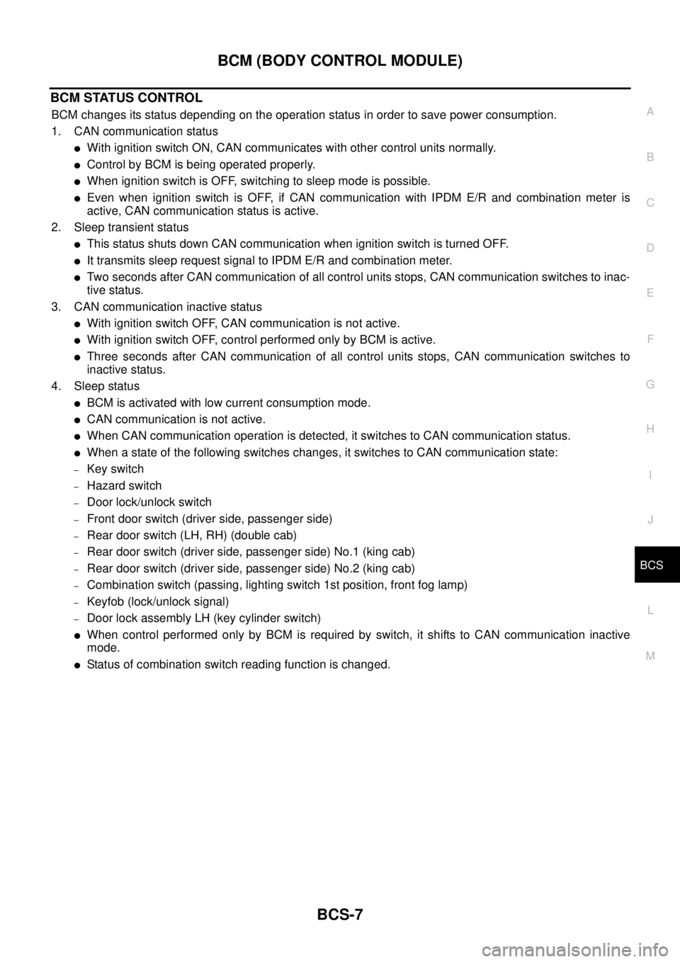
BCM STATUS CONTROL
BCM changes its status depending on the operation status in order to save power consumption.
1. CAN communication status
lWith ignition switch ON, CAN communicates with other control units normally.
lControl by BCM is being operated properly.
lWhen ignition switch is OFF, switching to sleep mode is possible.
lEven when ignition switch is OFF, if CAN communication with IPDM E/R and combination meter is
active, CAN communication status is active.
2. Sleep transient status
lThis status shuts down CAN communication when ignition switch is turned OFF.
lIt transmits sleep request signal to IPDM E/R and combination meter.
lTwo seconds after CAN communication of all control units stops, CAN communication switches to inac-
tive status.
3. CAN communication inactive status
lWith ignition switch OFF, CAN communication is not active.
lWith ignition switch OFF, control performed only by BCM is active.
lThree seconds after CAN communication of all control units stops, CAN communication switches to
inactive status.
4. Sleep status
lBCM is activated with low current consumption mode.
lCAN communication is not active.
lWhen CAN communication operation is detected, it switches to CAN communication status.
lWhen a state of the following switches changes, it switches to CAN communication state:
–Key switch
–Hazard switch
–Door lock/unlock switch
–Front door switch (driver side, passenger side)
–Rear door switch (LH, RH) (double cab)
–Rear door switch (driver side, passenger side) No.1 (king cab)
–Rear door switch (driver side, passenger side) No.2 (king cab)
–Combination switch (passing, lighting switch 1st position, front fog lamp)
–Keyfob (lock/unlock signal)
–Door lock assembly LH (key cylinder switch)
lWhen control performed only by BCM is required by switch, it shifts to CAN communication inactive
mode.
lStatus of combination switch reading function is changed.
Page 574 of 3171

BCS-8
BCM (BODY CONTROL MODULE)
SYSTEMS CONTROLLED BY BCM DIRECTLY
NOTE:
Power supply only. No system control.
SYSTEMS CONTROLLED BY BCM AND IPDM E/R
SYSTEMS CONTROLLED BY BCM AND COMBINATION METER
System Reference
Power door lock
lBL-21, "POWER DOOR LOCK SYSTEM"
lBL-55, "POWER DOOR LOCK—SUPER LOCK—"
Remote keyless entryBL-89, "MULTI-REMOTE CONTROL SYSTEM"
Power windowNOTEGW-15, "POWER WINDOW SYSTEM"
Sunroof systemNOTERF-10, "SUNROOF"
Room lamp timerLT-145, "INTERIOR ROOM LAMP"
Rear fog lampLT- 8 7 , "REAR FOG LAMP"
System Reference
NATSBL-170, "
NATS(Nissan Anti-Theft System)"
HeadlampLT- 5 , "HEADLAMP -CONVENTIONAL TYPE-"
Daytime light systemLT-31, "HEADLAMP - DAYTIME LIGHT SYSTEM -"
Auto light systemLT-49, "AUTO LIGHT SYSTEM"
Parking, license plate and tail lampsLT-125, "PARKING, LICENSE PLATE AND TAIL LAMPS"
Front fog lampLT-71, "FRONT FOG LAMP"
Front wiper, washerWW-4, "FRONT WIPER AND WASHER SYSTEM"
Headlamp washerWW-39, "HEADLAMP WASHER"
Rear window defoggerGW-47, "REAR WINDOW DEFOGGER"
System Reference
Warning chimeDI-51, "
WARNING CHIME"
Turn signal and hazard warning lampsLT-97, "TURN SIGNAL AND HAZARD WARNING LAMPS"
Page 575 of 3171

BCM (BODY CONTROL MODULE)
BCS-9
C
D
E
F
G
H
I
J
L
MA
B
BCS
MAJOR COMPONENTS AND CONTROL SYSTEM
CAN Communication System DescriptionEKS00PA2
Refer toLAN-23, "CAN COMMUNICATION".
System Input Output
Remote keyless entry system Keyfob
lAll-door locking actuator
lTurn signal lamp (LH, RH)
lCombination meter (Turn signal
lamp)
Power door lock system Door lock/unlock switch All-door locking actuator
Power supply (IGN) to power win-
dow and sunroofIgnition power supply Power window and sunroof system
Power supply (BAT) to power
window and sunroofBattery power supply Power window and sunroof system
Headlamp Combination switch IPDM E/R
Tail lamp Combination switch IPDM E/R
Front fog lamp Combination switch IPDM E/R
Rear fog lamp Combination switch
lRear fog lamp
lCombination meter
Turn signal lamp Combination switch
lTurn signal lamp
lCombination meter
Hazard lamp Hazard switch
lTurn signal lamp
lCombination meter
Room lamp timer
lKey switch
lKeyfob
lDoor lock/unlock switch
lFront door switch driver side
lAll-door switchInterior room lamp
Light warning chime
lCombination switch
lKey switch
lFront door switch driver sideCombination meter (warning buzzer)
Rain-sensing intermittent wiper
lCombination switch
lLight and rain sensorIPDM E/R
Vehicle-speed-sensing intermit-
tent wiper
lCombination switch
lCombination meterIPDM E/R
Headlamp washer Combination switch IPDM E/R
Rear window defogger
lRear window defogger switch
lIgnition switch (ACC, ON)IPDM E/R
A/C switch signal Front air control ECM
Blower fan switch signal Front air control ECM
Page 581 of 3171

BCM (BODY CONTROL MODULE)
BCS-15
C
D
E
F
G
H
I
J
L
MA
B
BCS
4. Select item to be diagnosed on “SELECT TEST ITEM” screen.
ITEMS OF EACH PART
NOTE:
CONSULT-II will only display systems the vehicle possesses.
WORK SUPPORT
Operation Procedure
1. Touch “BCM” on “SELECT TEST ITEM” screen.
PKIC0325E
System and itemCONSULT-II
displayDiagnostic test mode (Inspection by part)
WORK
SUPPORTSELF-
DIAG
RESULTSCAN DIAG
SUPPORT
MNTRDATA
MONITORECU
PA RT
NUMBERACTIVE
TESTCON-
FIGU-
RATION
BCM BCM´´ ´ ´ ´
Power door lock sys-
temDOOR LOCK´´´
Rear window defoggerREAR DEFOG-
GER´´
Warning chime BUZZER´´
Room lamp timer INT LAMP´´´
Headlamp HEAD LAMP´´´
Wiper WIPER´´´
Turn signal lamp
Hazard lampFLASHER´´
Blower fan switch sig-
nal
Air conditioner switch
signalAIR CONDI-
TONER´
Combination switch COMB SW´
NATS IMMU´´
Interior lamp battery
saverBATTERY
SAVER´´´
Theft alarm THEFT ALARM´´´
Retained power control RETAINED PWR´´´
Oil pressure switch SIGNAL BUFFER´´
PKIC0325E
Page 585 of 3171

BL-1
BODY, LOCK & SECURITY SYSTEM
IBODY
CONTENTS
C
D
E
F
G
H
J
K
L
M
SECTIONBL
A
B
BL
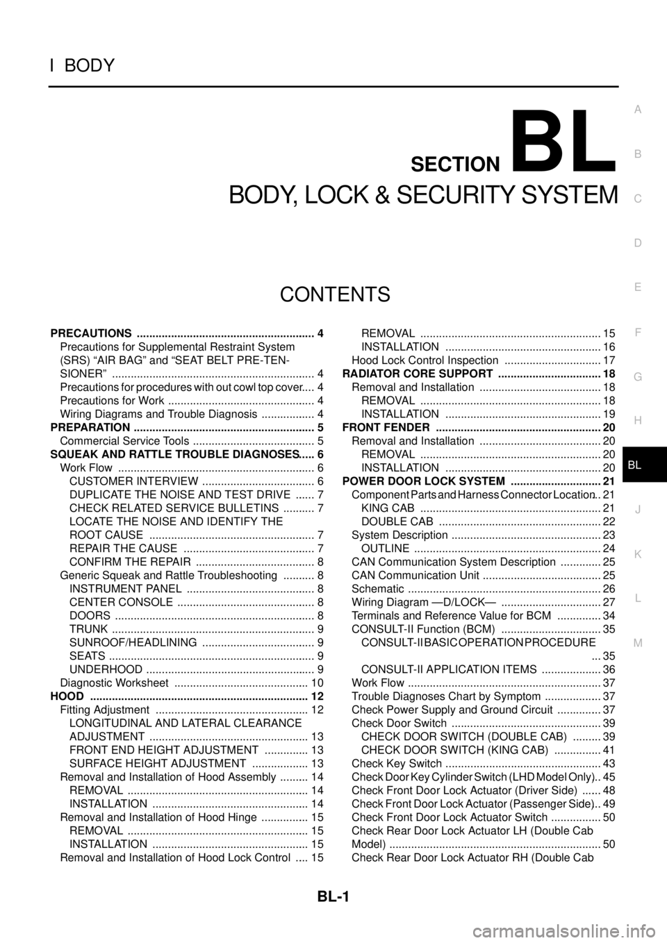
BODY, LOCK & SECURITY SYSTEM
PRECAUTIONS .......................................................... 4
Precautions for Supplemental Restraint System
(SRS)“AIRBAG”and“SEATBELTPRE-TEN-
SIONER” .................................................................. 4
Precautions for procedures with out cowl top cover..... 4
Precautions for Work ................................................ 4
Wiring Diagrams and Trouble Diagnosis .................. 4
PREPARATION ........................................................... 5
Commercial Service Tools ........................................ 5
SQUEAK AND RATTLE TROUBLE DIAGNOSES..... 6
Work Flow ................................................................ 6
CUSTOMER INTERVIEW ..................................... 6
DUPLICATE THE NOISE AND TEST DRIVE ....... 7
CHECK RELATED SERVICE BULLETINS ........... 7
LOCATE THE NOISE AND IDENTIFY THE
ROOT CAUSE ...................................................... 7
REPAIR THE CAUSE ........................................... 7
CONFIRM THE REPAIR ....................................... 8
Generic Squeak and Rattle Troubleshooting ........... 8
INSTRUMENT PANEL .......................................... 8
CENTER CONSOLE ............................................. 8
DOORS ................................................................. 8
TRUNK .................................................................. 9
SUNROOF/HEADLINING ..................................... 9
SEATS ................................................................... 9
UNDERHOOD ....................................................... 9
Diagnostic Worksheet ............................................ 10
HOOD ....................................................................... 12
Fitting Adjustment .................................................. 12
LONGITUDINAL AND LATERAL CLEARANCE
ADJUSTMENT .................................................... 13
FRONT END HEIGHT ADJUSTMENT ............... 13
SURFACE HEIGHT ADJUSTMENT ................... 13
Removal and Installation of Hood Assembly .......... 14
REMOVAL ........................................................... 14
INSTALLATION ................................................... 14
Removal and Installation of Hood Hinge ................ 15
REMOVAL ........................................................... 15
INSTALLATION ................................................... 15
Removal and Installation of Hood Lock Control ..... 15REMOVAL ........................................................... 15
INSTALLATION ................................................... 16
Hood Lock Control Inspection ................................ 17
RADIATOR CORE SUPPORT .................................. 18
Removal and Installation ........................................ 18
REMOVAL ........................................................... 18
INSTALLATION ................................................... 19
FRONT FENDER ...................................................... 20
Removal and Installation ........................................ 20
REMOVAL ........................................................... 20
INSTALLATION ................................................... 20
POWER DOOR LOCK SYSTEM .............................. 21
Component Parts and Harness Connector Location... 21
KING CAB ........................................................... 21
DOUBLE CAB ..................................................... 22
System Description ................................................. 23
OUTLINE ............................................................. 24
CAN Communication System Description .............. 25
CAN Communication Unit ....................................... 25
Schematic ............................................................... 26
Wiring Diagram —D/LOCK— ................................. 27
Terminals and Reference Value for BCM ............... 34
CONSULT-II Function (BCM) ................................. 35
CONSULT-II BASIC OPERATION PROCEDURE
... 35
CONSULT-II APPLICATION ITEMS .................... 36
Work Flow ............................................................... 37
Trouble Diagnoses Chart by Symptom ................... 37
Check Power Supply and Ground Circuit ............... 37
Check Door Switch ................................................. 39
CHECK DOOR SWITCH (DOUBLE CAB) .......... 39
CHECK DOOR SWITCH (KING CAB) ................ 41
Check Key Switch ................................................... 43
Check Door Key Cylinder Switch (LHD Model Only)... 45
Check Front Door Lock Actuator (Driver Side) ....... 48
Check Front Door Lock Actuator (Passenger Side)... 49
Check Front Door Lock Actuator Switch ................. 50
Check Rear Door Lock Actuator LH (Double Cab
Model) ..................................................................... 50
Check Rear Door Lock Actuator RH (Double Cab
Page 586 of 3171

BL-2
Model) ..................................................................... 51
Check RH and LH Rear Door Lock Actuator Switch... 51
Check Door Lock/Unlock Switch ............................ 52
Check Door Lock/Unlock Switch Indicator .............. 53
POWER DOOR LOCK — SUPER LOCK — ............ 55
Component Parts and Harness Connector Location... 55
KING CAB ........................................................... 55
DOUBLE CAB ..................................................... 56
System Description ................................................. 57
OUTLINE ............................................................. 58
OPERATION ........................................................ 58
CAN Communication System Description .............. 59
CAN Communication Unit ....................................... 59
Schematic ............................................................... 60
Wiring Diagram —D/LOCK— ................................. 61
Terminals and Reference Value for BCM ................ 69
CONSULT-II Function (BCM) .................................. 70
CONSULT-II BASIC OPERATION PROCEDURE
... 70
CONSULT-II APPLICATION ITEMS .................... 71
Work Flow ............................................................... 72
Trouble Diagnoses Chart by Symptom ................... 72
Check Power Supply and Ground Circuit ............... 73
Check Door Switch ................................................. 74
CHECK DOOR SWITCH (DOUBLE CAB) .......... 74
CHECK DOOR SWITCH (KING CAB) ................ 76
Check Key Switch ................................................... 78
Check Front Door Lock Actuator (Driver Side) ....... 80
Check Front Door Lock Actuator (Passenger Side)... 81
Check Front Door Lock Actuator Switch ................. 81
Check Rear Door Lock Actuator LH (Double Cab
Models) ................................................................... 82
Check Rear Door Lock Actuator RH (Double Cab
Models) ................................................................... 82
Check RH and LH Rear Door Lock Actuator Switch
(Double Cab Models) .............................................. 83
Check Super Lock Actuator (Driver Side) ............... 83
Check Super Lock Actuator (Passenger Side) ....... 84
Check Super Lock Actuator (Rear LH) ................... 84
Check Super Lock Actuator (Rear RH) .................. 85
Check Door Lock/Unlock Switch ............................ 86
Check Door Lock/Unlock Switch Indicator .............. 87
MULTI-REMOTE CONTROL SYSTEM ..................... 89
Component Parts and Harness Connector Location... 89
KING CAB ........................................................... 89
DOUBLE CAB ..................................................... 90
System Description ................................................. 91
INPUTS ............................................................... 91
OPERATING PROCEDURE ................................ 91
CAN Communication System Description .............. 92
Wiring Diagram — MULTI — For LHD Models ....... 93
Wiring Diagram — MULTI — For RHD Models ...... 97
Terminals and Reference Value for BCM ..............101
CONSULT-II Function (BCM) ................................102
CONSULT-II Inspection Procedure .......................102
“MULTI REMOTE ENT” .....................................102
CONSULT-II Application Items .............................103
“MULTI REMOTE ENT” .....................................103
Trouble Diagnosis Procedure ...............................104Trouble Diagnosis Chart by Symptom ..................105
Check Keyfob Battery and Function .....................106
Check ACC Switch ................................................107
Check Door Switch ...............................................108
CHECK DOOR SWITCH (DOUBLE CAB) .........108
CHECK DOOR SWITCH (KING CAB) ...............110
Check Key Switch .................................................113
Check Hazard Function ........................................114
Check Map Lamp and Ignition Keyhole Illumination
Function ................................................................114
ID Code Entry Procedure ......................................115
KEYFOB ID SET UP ..........................................115
CONSULT-II INSPECTION PROCEDURE ........115
Remote Controller Battery Replacement ..............116
DOOR ......................................................................117
Fitting Adjustment (King Cab) ...............................117
FRONT DOOR ...................................................118
REAR DOOR .....................................................118
STRIKER ADJUSTMENT ..................................118
Fitting Adjustment (Double Cab) ...........................119
FRONT DOOR ...................................................120
REAR DOOR .....................................................120
STRIKER ADJUSTMENT ..................................120
Removal and Installation of Front Door ................120
REMOVAL ..........................................................120
INSTALLATION ..................................................121
Removal and Installation of Rear Door (King Cab).121
REMOVAL ..........................................................121
INSTALLATION ..................................................122
Removal and Installation of Rear Door (Double Cab)
.123
REMOVAL ..........................................................123
INSTALLATION ..................................................123
Removal and Installation of Door Weather-strip
(King Cab) .............................................................124
REMOVAL ..........................................................124
INSTALLATION ..................................................124
Removal and Installation of Door Weather-strip
(Double Cab) .........................................................125
REMOVAL ..........................................................125
INSTALLATION ..................................................125
FRONT DOOR LOCK ..............................................126
Removal and Installation .......................................126
REMOVAL ..........................................................126
INSTALLATION ..................................................129
REAR DOOR LOCK ................................................130
Removal and Installation of Rear Door Lock (King
Cab) ......................................................................130
REMOVAL ..........................................................130
INSTALLATION ..................................................131
Removal and Installation of Rear Door Lock (Double
Cab) ......................................................................132
REMOVAL ..........................................................132
INSTALLATION ..................................................134
TAIL GATE ...............................................................135
Component Parts Location ...................................135
FUEL FILLER LID OPENER ...................................136
Removal and Installation of Fuel Filler Lid ............136
REMOVAL ..........................................................136
Page 587 of 3171

BL-3
C
D
E
F
G
H
J
K
L
MA
B
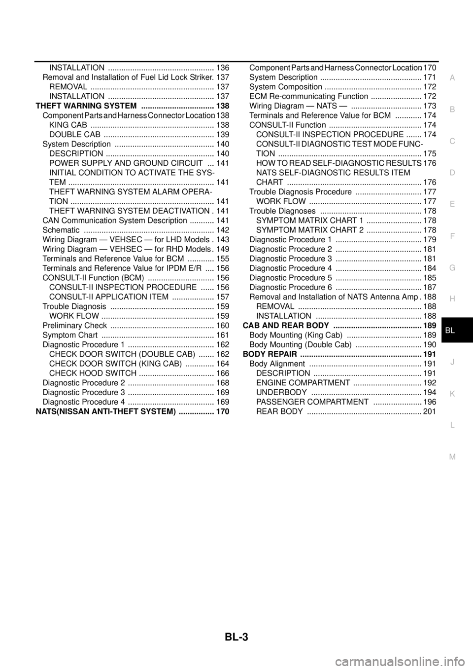
BL INSTALLATION ................................................. 136
Removal and Installation of Fuel Lid Lock Striker. 137
REMOVAL ......................................................... 137
INSTALLATION ................................................. 137
THEFT WARNING SYSTEM .................................. 138
Component Parts and Harness Connector Location. 138
KING CAB ......................................................... 138
DOUBLE CAB ................................................... 139
System Description .............................................. 140
DESCRIPTION .................................................. 140
POWER SUPPLY AND GROUND CIRCUIT .... 141
INITIAL CONDITION TO ACTIVATE THE SYS-
TEM ................................................................... 141
THEFT WARNING SYSTEM ALARM OPERA-
TION .................................................................. 141
THEFT WARNING SYSTEM DEACTIVATION . 141
CAN Communication System Description ............ 141
Schematic ............................................................ 142
Wiring Diagram — VEHSEC — for LHD Models . 143
Wiring Diagram — VEHSEC — for RHD Models . 149
Terminals and Reference Value for BCM ............. 155
Terminals and Reference Value for IPDM E/R ..... 156
CONSULT-II Function (BCM) ............................... 156
CONSULT-II INSPECTION PROCEDURE ....... 156
CONSULT-II APPLICATION ITEM .................... 157
Trouble Diagnosis ................................................ 159
WORK FLOW .................................................... 159
Preliminary Check ................................................ 160
Symptom Chart .................................................... 161
Diagnostic Procedure 1 ........................................ 162
CHECK DOOR SWITCH (DOUBLE CAB) ........ 162
CHECK DOOR SWITCH (KING CAB) .............. 164
CHECK HOOD SWITCH ................................... 166
Diagnostic Procedure 2 ........................................ 168
Diagnostic Procedure 3 ........................................ 169
Diagnostic Procedure 4 ........................................ 169
NATS(NISSAN ANTI-THEFT SYSTEM) ................. 170Component Parts and Harness Connector Location.170
System Description ...............................................171
System Composition .............................................172
ECM Re-communicating Function ........................172
Wiring Diagram — NATS — .................................173
Terminals and Reference Value for BCM .............174
CONSULT-II Function ...........................................174
CONSULT-II INSPECTION PROCEDURE ........174
CONSULT-II DIAGNOSTIC TEST MODE FUNC-
TION ..................................................................175
HOW TO READ SELF-DIAGNOSTIC RESULTS.176
NATS SELF-DIAGNOSTIC RESULTS ITEM
CHART ..............................................................176
Trouble Diagnosis Procedure ...............................177
WORK FLOW ....................................................177
Trouble Diagnoses ...............................................178
SYMPTOM MATRIX CHART 1 ..........................178
SYMPTOM MATRIX CHART 2 ..........................178
Diagnostic Procedure 1 ........................................179
Diagnostic Procedure 2 ........................................181
Diagnostic Procedure 3 ........................................181
Diagnostic Procedure 4 ........................................184
Diagnostic Procedure 5 ........................................185
Diagnostic Procedure 6 ........................................187
Removal and Installation of NATS Antenna Amp . 188
REMOVAL .........................................................188
INSTALLATION .................................................188
CAB AND REAR BODY .........................................189
Body Mounting (King Cab) ...................................189
Body Mounting (Double Cab) ...............................190
BODY REPAIR ........................................................191
Body Alignment ....................................................191
DESCRIPTION ..................................................191
ENGINE COMPARTMENT ................................192
UNDERBODY ...................................................194
PASSENGER COMPARTMENT .......................196
REAR BODY .....................................................201
Page 590 of 3171

BL-6
SQUEAK AND RATTLE TROUBLE DIAGNOSES
SQUEAK AND RATTLE TROUBLE DIAGNOSES
PFP:00000
Work FlowEIS00DI2
CUSTOMER INTERVIEW
Interview the customer if possible, to determine the conditions that exist when the noise occurs. Use the Diag-
nostic Worksheet during the interview to document the facts and conditions when the noise occurs and any
customer's comments; refer toBL-10, "
Diagnostic Worksheet". This information is necessary to duplicate the
conditions that exist when the noise occurs.
lThe customer may not be able to provide a detailed description or the location of the noise. Attempt to
obtain all the facts and conditions that exist when the noise occurs (or does not occur).
lIf there is more than one noise in the vehicle, be sure to diagnose and repair the noise that the customer
is concerned about. This can be accomplished by test driving the vehicle with the customer.
lAfter identifying the type of noise, isolate the noise in terms of its characteristics. The noise characteristics
are provided so the customer, service adviser and technician are all speaking the same language when
defining the noise.
lSqueak —(Like tennis shoes on a clean floor)
Squeak characteristics include the light contact/fast movement/brought on by road conditions/hard sur-
faces=higher pitch noise/softer surfaces=lower pitch noises/edge to surface=chirping
lCreak—(Like walking on an old wooden floor)
Creak characteristics include firm contact/slow movement/twisting with a rotational movement/pitch
dependent on materials/often brought on by activity.
lRattle—(Like shaking a baby rattle)
Rattle characteristics include the fast repeated contact/vibration or similar movement/loose parts/missing
clip or fastener/incorrect clearance.
lKnock —(Like a knock on a door)
Knock characteristics include hollow sounding/sometimes repeating/often brought on by driver action.
lTick—(Like a clock second hand)
Tick characteristics include gentle contacting of light materials/loose components/can be caused by driver
action or road conditions.
lThump—(Heavy, muffled knock noise)
Thump characteristics include softer knock/dead sound often brought on by activity.
lBuzz—(Like a bumble bee)
Buzz characteristics include high frequency rattle/firm contact.
lOften the degree of acceptable noise level will vary depending upon the person. A noise that you may
judge as acceptable may be very irritating to the customer.
lWeather conditions, especially humidity and temperature, may have a great effect on noise level.
SBT842