Page 620 of 3171
BL-36
POWER DOOR LOCK SYSTEM
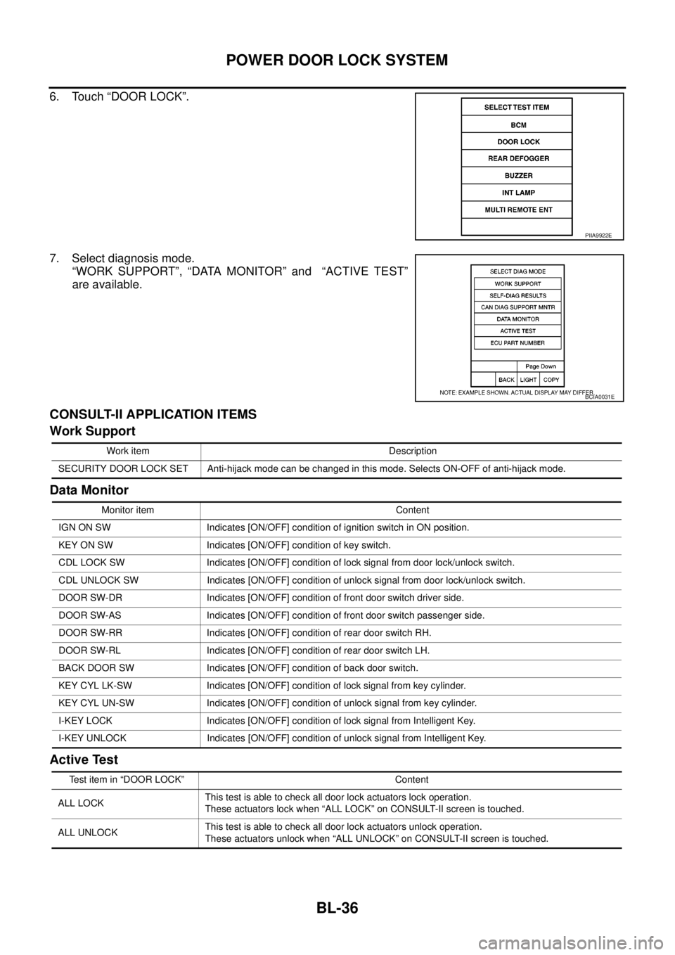
6. Touch “DOOR LOCK”.
7. Select diagnosis mode.
“WORK SUPPORT”, “DATA MONITOR” and “ACTIVE TEST”
are available.
CONSULT-II APPLICATION ITEMS
Work Support
Data Monitor
Active Test
PIIA9922E
BCIA0031E
Work item Description
SECURITY DOOR LOCK SET Anti-hijack mode can be changed in this mode. Selects ON-OFF of anti-hijack mode.
Monitor item Content
IGN ON SW Indicates [ON/OFF] condition of ignition switch in ON position.
KEY ON SW Indicates [ON/OFF] condition of key switch.
CDL LOCK SW Indicates [ON/OFF] condition of lock signal from door lock/unlock switch.
CDL UNLOCK SW Indicates [ON/OFF] condition of unlock signal from door lock/unlock switch.
DOOR SW-DR Indicates [ON/OFF] condition of front door switch driver side.
DOOR SW-AS Indicates [ON/OFF] condition of front door switch passenger side.
DOOR SW-RR Indicates [ON/OFF] condition of rear door switch RH.
DOOR SW-RL Indicates [ON/OFF] condition of rear door switch LH.
BACK DOOR SW Indicates [ON/OFF] condition of back door switch.
KEY CYL LK-SW Indicates [ON/OFF] condition of lock signal from key cylinder.
KEY CYL UN-SW Indicates [ON/OFF] condition of unlock signal from key cylinder.
I-KEY LOCK Indicates [ON/OFF] condition of lock signal from Intelligent Key.
I-KEY UNLOCK Indicates [ON/OFF] condition of unlock signal from Intelligent Key.
Test item in “DOOR LOCK” Content
ALL LOCKThis test is able to check all door lock actuators lock operation.
These actuators lock when “ALL LOCK” on CONSULT-II screen is touched.
ALL UNLOCKThis test is able to check all door lock actuators unlock operation.
These actuators unlock when “ALL UNLOCK” on CONSULT-II screen is touched.
Page 621 of 3171
POWERDOORLOCKSYSTEM
BL-37
C
D
E
F
G
H
J
K
L
MA
B
BL
Work FlowEIS00D81
1. Check the symptom and customer's requests.
2. Understand the outline of system. Refer toBL-23, "
System Description".
3. According to the trouble diagnosis, repair or replace the cause of the malfunction. Refer toBL-37, "
Trou-
ble Diagnoses Chart by Symptom".
4. Does power door lock system operate normally?
YES: GO TO 5.
NO:GOTO2.
5. INSPECTION END.
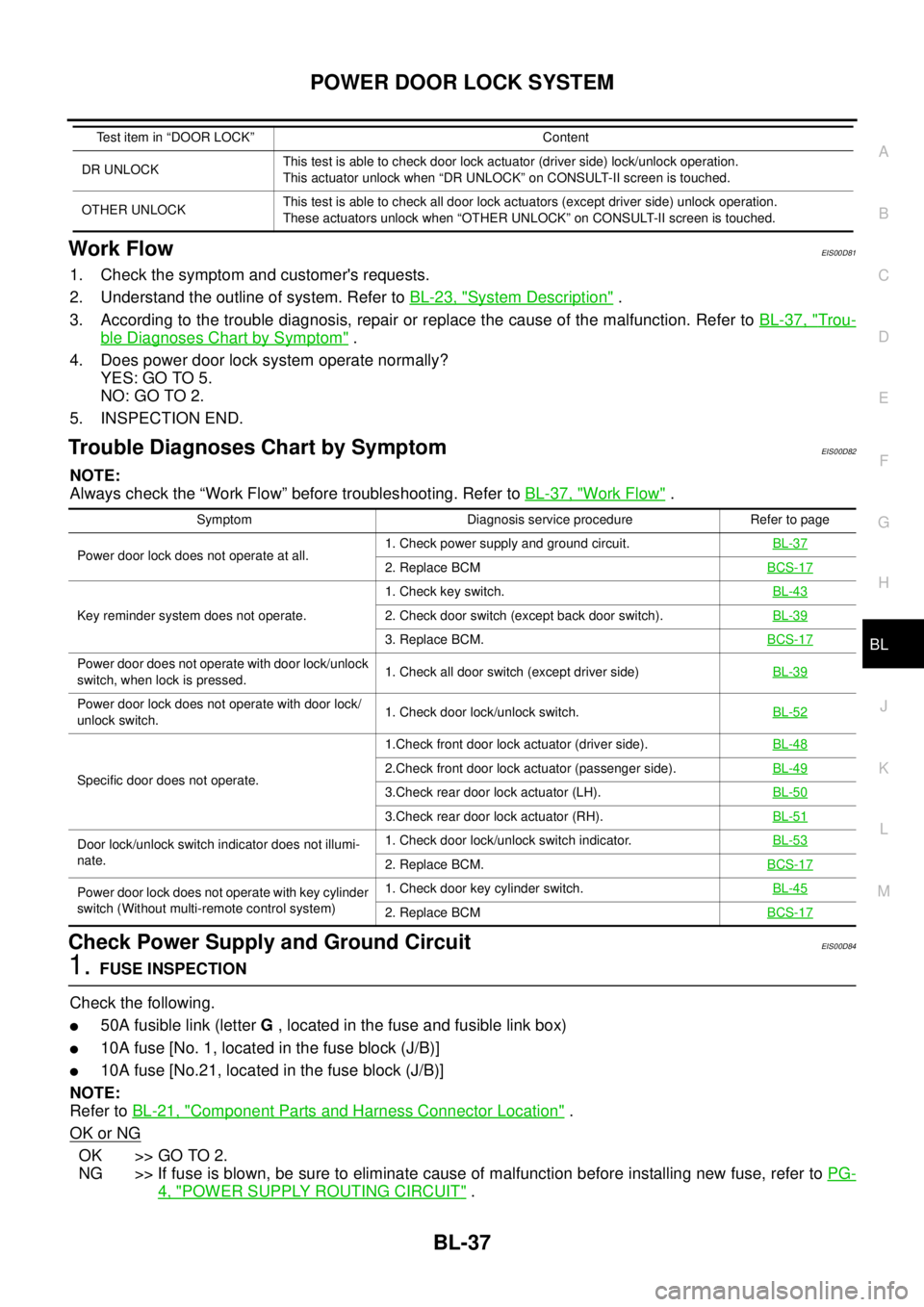
Trouble Diagnoses Chart by SymptomEIS00D82
NOTE:
Always check the “Work Flow” before troubleshooting. Refer toBL-37, "
Work Flow".
Check Power Supply and Ground CircuitEIS00D84
1.FUSE INSPECTION
Check the following.
l50A fusible link (letterG, located in the fuse and fusible link box)
l10A fuse [No. 1, located in the fuse block (J/B)]
l10A fuse [No.21, located in the fuse block (J/B)]
NOTE:
Refer toBL-21, "
Component Parts and Harness Connector Location".
OK or NG
OK >> GO TO 2.
NG >> If fuse is blown, be sure to eliminate cause of malfunction before installing new fuse, refer toPG-
4, "POWER SUPPLY ROUTING CIRCUIT".
DR UNLOCKThis test is able to check door lock actuator (driver side) lock/unlock operation.
This actuator unlock when “DR UNLOCK” on CONSULT-II screen is touched.
OTHER UNLOCKThis test is able to check all door lock actuators (except driver side) unlock operation.
These actuators unlock when “OTHER UNLOCK” on CONSULT-II screen is touched. Test item in “DOOR LOCK” Content
Symptom Diagnosis service procedure Refer to page
Power door lock does not operate at all.1. Check power supply and ground circuit.BL-37
2. Replace BCMBCS-17
Key reminder system does not operate.1. Check key switch.BL-432. Check door switch (except back door switch).BL-39
3. Replace BCM.BCS-17
Power door does not operate with door lock/unlock
switch, when lock is pressed.1. Check all door switch (except driver side)BL-39
Power door lock does not operate with door lock/
unlock switch.1. Check door lock/unlock switch.BL-52
Specific door does not operate.1.Check front door lock actuator (driver side).BL-482.Check front door lock actuator (passenger side).BL-49
3.Check rear door lock actuator (LH).BL-50
3.Check rear door lock actuator (RH).BL-51
Door lock/unlock switch indicator does not illumi-
nate.1. Check door lock/unlock switch indicator.BL-53
2. Replace BCM.BCS-17
Power door lock does not operate with key cylinder
switch (Without multi-remote control system)1. Check door key cylinder switch.BL-45
2. Replace BCMBCS-17
Page 622 of 3171
BL-38
POWER DOOR LOCK SYSTEM
2.CHECK POWER SUPPLY CIRCUIT
1. Turn ignition switch OFF.
2. Disconnect BCM connector.
3. Check voltage between BCM and ground.
OK or NG
OK >> GO TO 3.
NG >> Repair or replace BCM power supply circuit.
3.CHECK GROUND CIRCUIT
Check continuity between BCM connector M44 terminal 55 and
ground.
OK or NG
OK >> BCM power supply and ground circuit is OK.
NG >> Repair or replace BCM ground circuit.
ConnectorTerminals Ignition switch position
(+) (-) OFF ACC ON
M42 3
Ground0V 0VBattery
voltage
M43 41
Battery
voltageBattery
voltageBattery
voltage
M44 57
MIIB0823E
55 – Ground : Continuity should exist.
MIIB0824E
Page 623 of 3171
POWERDOORLOCKSYSTEM
BL-39
C
D
E
F
G
H
J
K
L
MA
B
BL
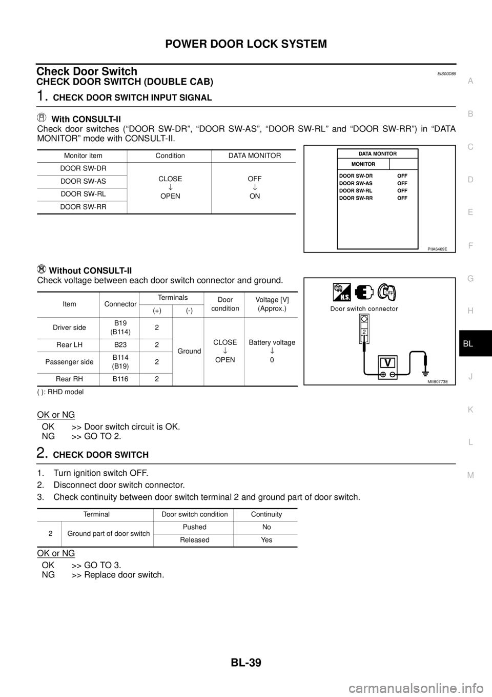
Check Door SwitchEIS00D85
CHECK DOOR SWITCH (DOUBLE CAB)
1.CHECK DOOR SWITCH INPUT SIGNAL
With CONSULT-II
Check door switches (“DOOR SW-DR”, “DOOR SW-AS”, “DOOR SW-RL” and “DOOR SW-RR”) in “DATA
MONITOR” mode with CONSULT-II.
Without CONSULT-II
Check voltage between each door switch connector and ground.
( ): RHD model
OK or NG
OK >> Door switch circuit is OK.
NG >> GO TO 2.
2.CHECK DOOR SWITCH
1. Turn ignition switch OFF.
2. Disconnect door switch connector.
3. Check continuity between door switch terminal 2 and ground part of door switch.
OK or NG
OK >> GO TO 3.
NG >> Replace door switch.
Monitor item Condition DATA MONITOR
DOOR SW-DR
CLOSE
¯
OPENOFF
¯
ON DOOR SW-AS
DOOR SW-RL
DOOR SW-RR
PIIA6469E
Item ConnectorTerminals
Door
conditionVo l ta g e [V ]
(Approx.)
(+) (-)
Driver sideB19
(B114)2
GroundCLOSE
¯
OPENBattery voltage
¯
0 Rear LH B23 2
Passenger sideB114
(B19)2
Rear RH B116 2
MIIB0773E
Terminal Door switch condition Continuity
2 Ground part of door switchPushed No
Released Yes
Page 624 of 3171
BL-40
POWER DOOR LOCK SYSTEM
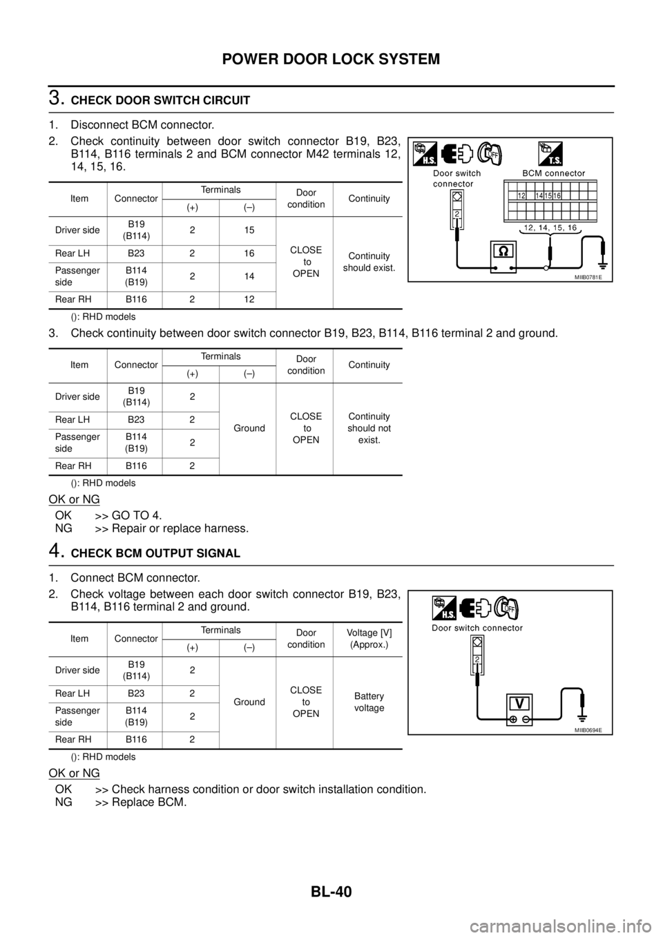
3.CHECK DOOR SWITCH CIRCUIT
1. Disconnect BCM connector.
2. Check continuity between door switch connector B19, B23,
B114, B116 terminals 2 and BCM connector M42 terminals 12,
14, 15, 16.
(): RHD models
3. Check continuity between door switch connector B19, B23, B114, B116 terminal 2 and ground.
(): RHD models
OK or NG
OK >> GO TO 4.
NG >> Repair or replace harness.
4.CHECK BCM OUTPUT SIGNAL
1. Connect BCM connector.
2. Check voltage between each door switch connector B19, B23,
B114, B116 terminal 2 and ground.
(): RHD models
OK or NG
OK >> Check harness condition or door switch installation condition.
NG >> Replace BCM.
Item ConnectorTerminals
Door
conditionContinuity
(+) (–)
Driver sideB19
(B114)215
CLOSE
to
OPENContinuity
should exist. Rear LH B23 2 16
Passenger
sideB114
(B19)214
Rear RH B116 2 12
Item ConnectorTerminals
Door
conditionContinuity
(+) (–)
Driver sideB19
(B114)2
GroundCLOSE
to
OPENContinuity
should not
exist. Rear LH B23 2
Passenger
sideB114
(B19)2
Rear RH B116 2
MIIB0781E
Item ConnectorTerminals
Door
conditionVo l ta g e [V ]
(Approx.)
(+) (–)
Driver sideB19
(B114)2
GroundCLOSE
to
OPENBattery
voltage Rear LH B23 2
Passenger
sideB114
(B19)2
Rear RH B116 2
MIIB0694E
Page 625 of 3171
POWERDOORLOCKSYSTEM
BL-41
C
D
E
F
G
H
J
K
L
MA
B
BL
CHECK DOOR SWITCH (KING CAB)
1.CHECK DOOR SWITCHES INPUT SIGNAL
With CONSULT-II
Check door switches (“DOOR SW-DR”, “DOOR SW-AS”) in DATA MONITOR mode with CONSULT-II. Refer
toBL-36, "
Data Monitor".
lWhen any doors are open:
lWhen any doors are closed:
Without CONSULT-II
Check voltage between door switch connector D74 (Front LH), D94 (Front RH) terminal 2, D72 (Rear upper
LH), D92 (Rear upper RH), D71 (Rear lower LH), D91 (Rear lower RH) terminals 1, 2 and ground.
(): RHD MODELS
OK or NG
OK >> System is OK.
NG >> GO TO 2.DOOR SW-DR : OFF
DOOR SW-AS : OFF
DOOR SW-DR : OFF
DOOR SW-AS : OFF
WIIA0560E
Item ConnectorTerminals
ConditionVo l ta g e (V )
(Approx.)
(+) (-)
Front door
switch LHD74
(D94)
2
GroundOpen
¯
Closed0
¯
Battery
voltage Front door
switch RHD94
(D74)
Rear door
switch No.2 LHD72
(D92)
Rear door
switch No.2 RHD92
(D72)
1 Rear door
switch No.1 LHD71
(D91)
Rear door
switch No.1 RHD91
(D71)
MIIB1062E
Page 626 of 3171
BL-42
POWER DOOR LOCK SYSTEM
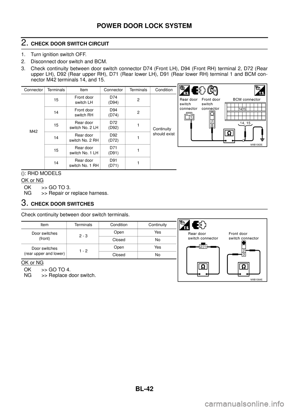
2.CHECK DOOR SWITCH CIRCUIT
1. Turn ignition switch OFF.
2. Disconnect door switch and BCM.
3. Check continuity between door switch connector D74 (Front LH), D94 (Front RH) terminal 2, D72 (Rear
upper LH), D92 (Rear upper RH), D71 (Rear lower LH), D91 (Rear lower RH) terminal 1 and BCM con-
nector M42 terminals 14, and 15.
(): RHD MODELS
OK or NG
OK >> GO TO 3.
NG >> Repair or replace harness.
3.CHECK DOOR SWITCHES
Check continuity between door switch terminals.
OK or NG
OK >> GO TO 4.
NG >> Replace door switch.
Connector Terminals Item Connector Terminals Condition
M4215Front door
switch LHD74
(D94)2
Continuity
should exist 14Front door
switch RHD94
(D74)2
15Rear door
switch No. 2 LHD72
(D92)1
14Rear door
switch No. 2 RHD92
(D72)1
15Rear door
switch No. 1 LHD71
(D91)1
14Rear door
switch No. 1 RHD91
(D71)1
MIIB1063E
Item Terminals Condition Continuity
Door switches
(front)2-3Open Yes
Closed No
Door switches
(rear upper and lower)1-2Open Yes
Closed No
MIIB1064E
Page 627 of 3171
POWERDOORLOCKSYSTEM
BL-43
C
D
E
F
G
H
J
K
L
MA
B
BL
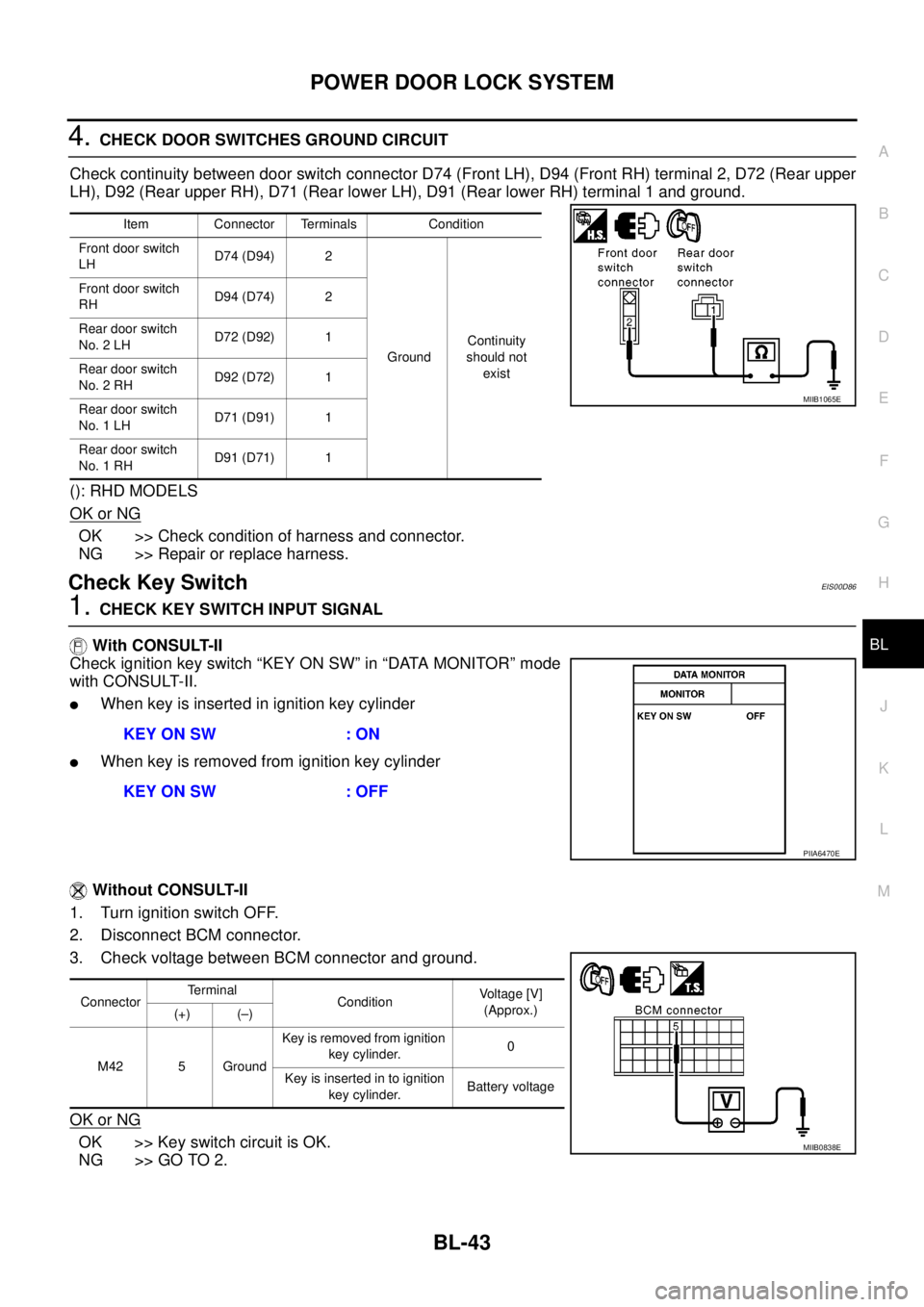
4.CHECK DOOR SWITCHES GROUND CIRCUIT
Check continuity between door switch connector D74 (Front LH), D94 (Front RH) terminal 2, D72 (Rear upper
LH), D92 (Rear upper RH), D71 (Rear lower LH), D91 (Rear lower RH) terminal 1 and ground.
(): RHD MODELS
OK or NG
OK >> Check condition of harness and connector.
NG >> Repair or replace harness.
Check Key SwitchEIS00D86
1.CHECK KEY SWITCH INPUT SIGNAL
With CONSULT-II
Check ignition key switch “KEY ON SW” in “DATA MONITOR” mode
with CONSULT-II.
lWhen key is inserted in ignition key cylinder
lWhen key is removed from ignition key cylinder
Without CONSULT-II
1. Turn ignition switch OFF.
2. Disconnect BCM connector.
3. Check voltage between BCM connector and ground.
OK or NG
OK >> Key switch circuit is OK.
NG >> GO TO 2.
Item Connector Terminals Condition
Front door switch
LHD74 (D94) 2
GroundContinuity
should not
exist Front door switch
RHD94 (D74) 2
Rear door switch
No. 2 LHD72 (D92) 1
Rear door switch
No. 2 RHD92 (D72) 1
Rear door switch
No. 1 LHD71 (D91) 1
Rear door switch
No. 1 RHD91 (D71) 1
MIIB1065E
KEY ON SW : ON
KEY ON SW : OFF
PIIA6470E
ConnectorTerminal
ConditionVoltage [V]
(Approx.)
(+) (–)
M42 5 GroundKey is removed from ignition
key cylinder.0
Keyisinsertedintoignition
key cylinder.Battery voltage
MIIB0838E