Page 628 of 3171
BL-44
POWER DOOR LOCK SYSTEM
2.CHECK KEY SWITCH SIGNAL CIRCUIT
1. Turn ignition switch OFF.
2. Disconnect BCM connector and key switch connector.
3. Check continuity between BCM harness connector M42 terminal
5 and key switch harness connector M35 terminal 1.
4. Check continuity between BCM harness connector M42 terminal
5 and ground.
OK or NG
OK >> GO TO 3.
NG >> Repair or replace harness between key switch and
BCM.
3.CHECK KEY SWITCH
Check continuity between key switch connector M35 terminals 1 and
2.
OK or NG
OK >> Check the following
l10A fuse [No. 22, located in the fuse block (J/B)]
lHarness for open or short between key switch and
fuse.
NG >> Replace key cylinder assembly.5 – 1 : Continuity should exist.
5 – Ground : Continuity should not exist.
MIIB0884E
Terminal Condition Continuity
12Key is removed from ignition key cylinder. No
Key is inserted in ignition key cylinder. Yes
MIIB0840E
Page 629 of 3171
POWERDOORLOCKSYSTEM
BL-45
C
D
E
F
G
H
J
K
L
MA
B
BL
Check Door Key Cylinder Switch (LHD Model Only)EIS00DGO
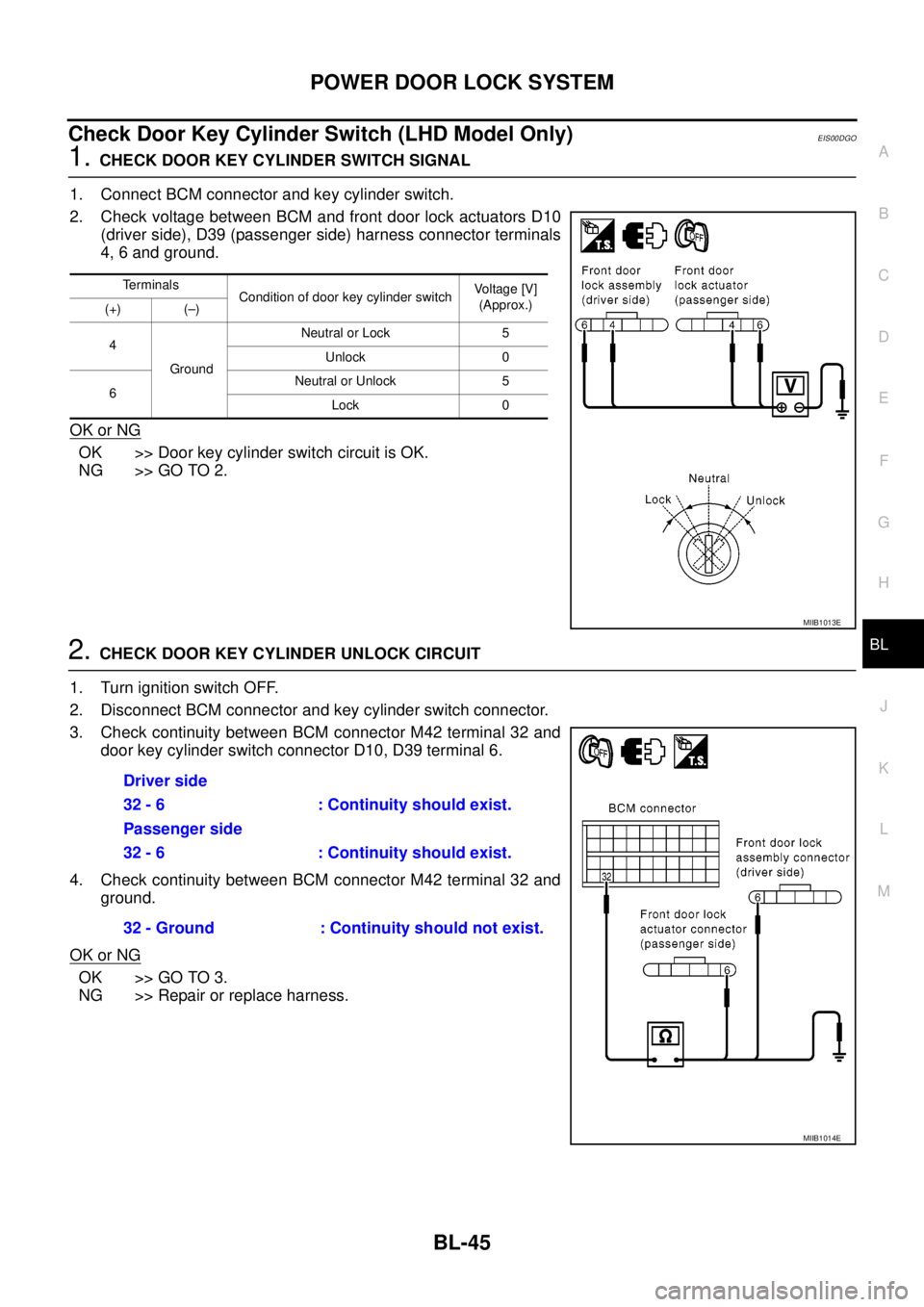
1.CHECK DOOR KEY CYLINDER SWITCH SIGNAL
1. Connect BCM connector and key cylinder switch.
2. Check voltage between BCM and front door lock actuators D10
(driver side), D39 (passenger side) harness connector terminals
4, 6 and ground.
OK or NG
OK >> Door key cylinder switch circuit is OK.
NG >> GO TO 2.
2.CHECK DOOR KEY CYLINDER UNLOCK CIRCUIT
1. Turn ignition switch OFF.
2. Disconnect BCM connector and key cylinder switch connector.
3. Check continuity between BCM connector M42 terminal 32 and
door key cylinder switch connector D10, D39 terminal 6.
4. Check continuity between BCM connector M42 terminal 32 and
ground.
OK or NG
OK >> GO TO 3.
NG >> Repair or replace harness.
Terminals
Condition of door key cylinder switchVo l ta g e [V ]
(Approx.)
(+) (–)
4
GroundNeutral or Lock 5
Unlock 0
6Neutral or Unlock 5
Lock 0
MIIB1013E
Driver side
32 - 6 : Continuity should exist.
Passenger side
32 - 6 : Continuity should exist.
32 - Ground : Continuity should not exist.
MIIB1014E
Page 630 of 3171
BL-46
POWER DOOR LOCK SYSTEM
3.CHECK DOOR KEY CYLINDER LOCK CIRCUIT
1. Check continuity between BCM connector M42 terminal 34 and
door key cylinder switch connector D10, D39 terminal 4.
2. Check continuity between BCM connector M42 terminal 34 and
ground.
OK or NG
OK >> GO TO 4.
NG >> Repair or replace harness.
4.CHECK DOOR KEY CYLINDER LOCK GROUND HARNESS
Check continuity between key cylinder switch connector D10, D39
terminal 5 and ground.
OK or NG
OK >> GO TO 5.
NG >> Repair or replace harness.Driver side
34 - 4 : Continuity should exist.
Passenger side
34 - 4 : Continuity should exist.
34 - Ground : Continuity should not
exist.
MIIB1015E
5 - Ground : Continuity should exist.
MIIB0995E
Page 631 of 3171
POWERDOORLOCKSYSTEM
BL-47
C
D
E
F
G
H
J
K
L
MA
B
BL
5.CHECK DOOR KEY CYLINDER SWITCH
Check continuity between door key cylinder switch connectors D10
and D39 driver and/or passenger side terminals 4, 5 and 6.
OK or NG
OK >> Check condition of harness and connector.
NG >> Replace door key cylinder switch.
TerminalsCondition of door key cylinder
switchContinuity
Driver sidePassenger
side
4
5Neutral or Unlock No Yes
Lock Yes No
6Neutral or Lock No Yes
Unlock Yes No
MIIB0996E
Page 632 of 3171
BL-48
POWER DOOR LOCK SYSTEM
Check Front Door Lock Actuator (Driver Side)
EIS00D88
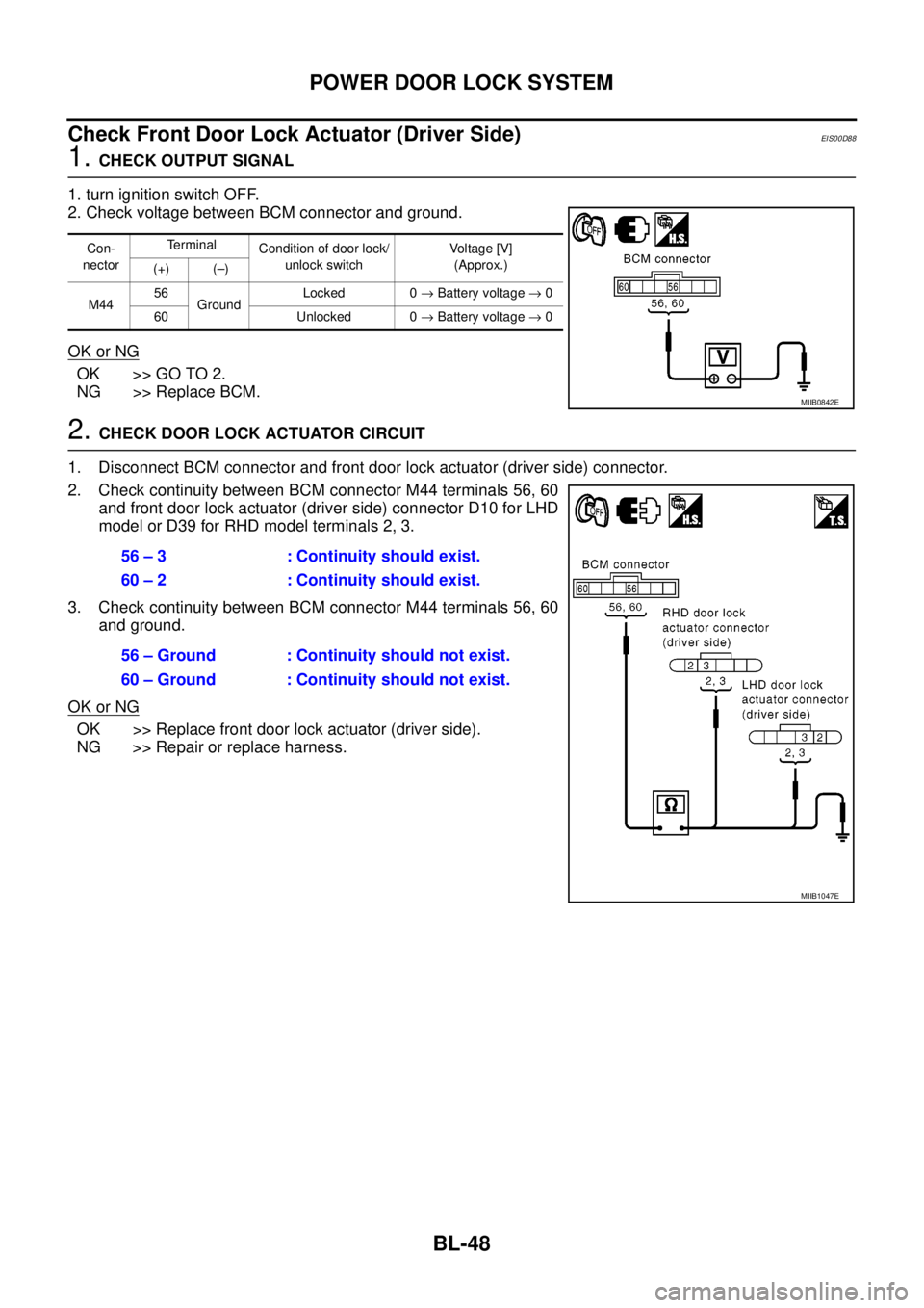
1.CHECK OUTPUT SIGNAL
1. turn ignition switch OFF.
2. Check voltage between BCM connector and ground.
OK or NG
OK >> GO TO 2.
NG >> Replace BCM.
2.CHECK DOOR LOCK ACTUATOR CIRCUIT
1. Disconnect BCM connector and front door lock actuator (driver side) connector.
2. Check continuity between BCM connector M44 terminals 56, 60
and front door lock actuator (driver side) connector D10 for LHD
model or D39 for RHD model terminals 2, 3.
3. Check continuity between BCM connector M44 terminals 56, 60
and ground.
OK or NG
OK >> Replace front door lock actuator (driver side).
NG >> Repair or replace harness.
Con-
nectorTerminal
Condition of door lock/
unlock switchVo l ta g e [V ]
(Approx.)
(+) (–)
M4456
GroundLocked 0®Battery voltage®0
60 Unlocked 0®Battery voltage®0
MIIB0842E
56 – 3 : Continuity should exist.
60 – 2 : Continuity should exist.
56 – Ground : Continuity should not exist.
60 – Ground : Continuity should not exist.
MIIB1047E
Page 633 of 3171
POWERDOORLOCKSYSTEM
BL-49
C
D
E
F
G
H
J
K
L
MA
B
BL
Check Front Door Lock Actuator (Passenger Side)EIS00D8A
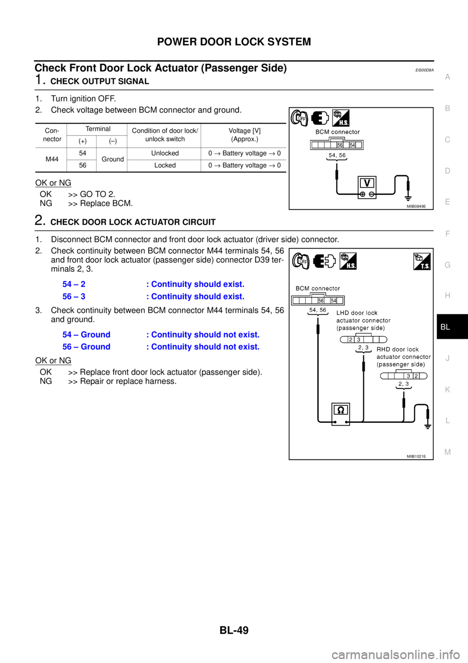
1.CHECK OUTPUT SIGNAL
1. Turn ignition OFF.
2. Check voltage between BCM connector and ground.
OK or NG
OK >> GO TO 2.
NG >> Replace BCM.
2.CHECK DOOR LOCK ACTUATOR CIRCUIT
1. Disconnect BCM connector and front door lock actuator (driver side) connector.
2. Check continuity between BCM connector M44 terminals 54, 56
and front door lock actuator (passenger side) connector D39 ter-
minals 2, 3.
3. Check continuity between BCM connector M44 terminals 54, 56
and ground.
OK or NG
OK >> Replace front door lock actuator (passenger side).
NG >> Repair or replace harness.
Con-
nectorTerminal
Condition of door lock/
unlock switchVoltag e [V]
(Approx.)
(+) (–)
M4454
GroundUnlocked 0®Battery voltage®0
56 Locked 0®Battery voltage®0
MIIB0849E
54 – 2 : Continuity should exist.
56 – 3 : Continuity should exist.
54 – Ground : Continuity should not exist.
56 – Ground : Continuity should not exist.
MIIB1021E
Page 634 of 3171
BL-50
POWER DOOR LOCK SYSTEM
Check Front Door Lock Actuator Switch
EIS00DWW
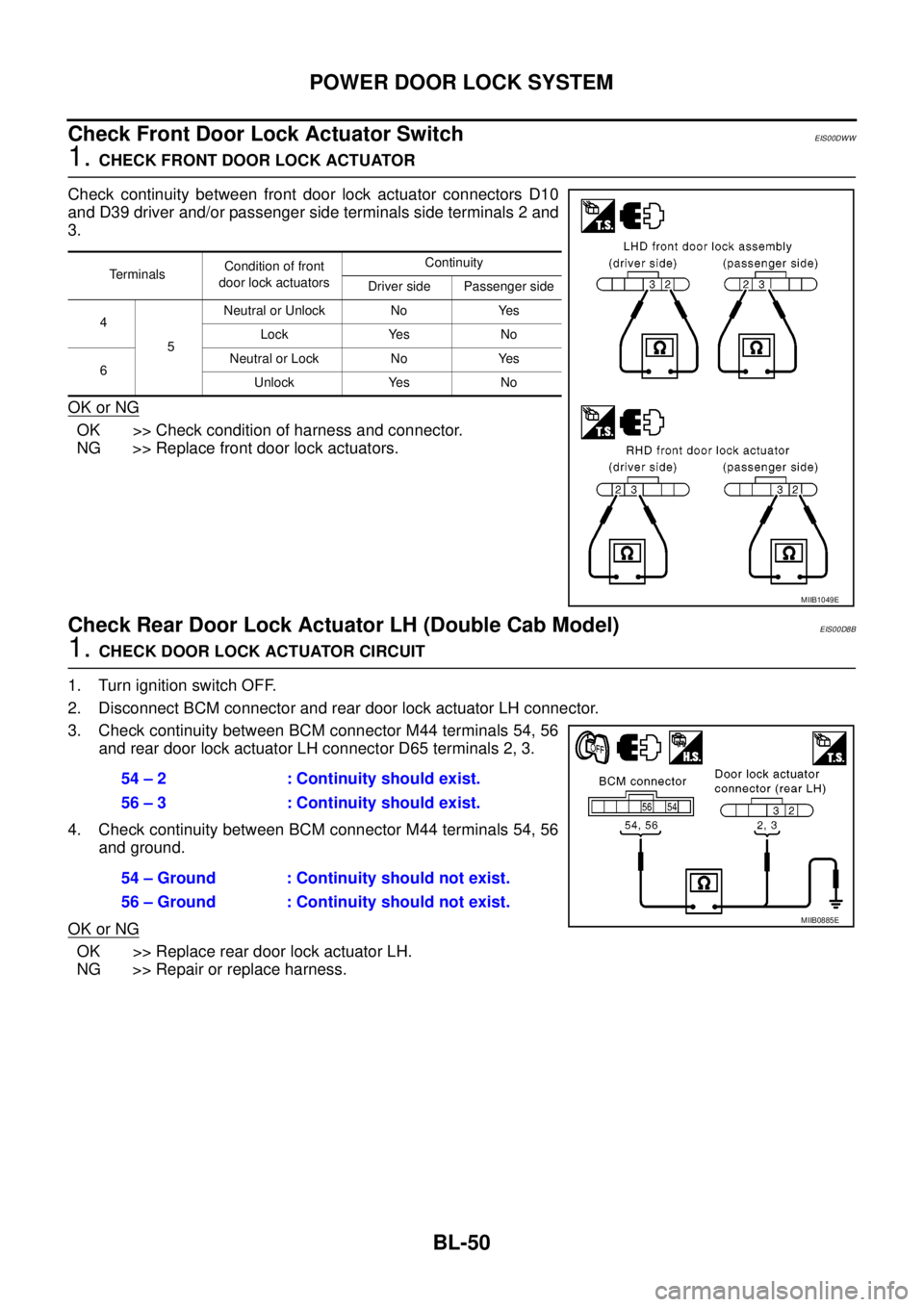
1.CHECK FRONT DOOR LOCK ACTUATOR
Check continuity between front door lock actuator connectors D10
and D39 driver and/or passenger side terminals side terminals 2 and
3.
OK or NG
OK >> Check condition of harness and connector.
NG >> Replace front door lock actuators.
CheckRearDoorLockActuatorLH(DoubleCabModel)EIS00D8B
1.CHECK DOOR LOCK ACTUATOR CIRCUIT
1. Turn ignition switch OFF.
2. Disconnect BCM connector and rear door lock actuator LH connector.
3. Check continuity between BCM connector M44 terminals 54, 56
and rear door lock actuator LH connector D65 terminals 2, 3.
4. Check continuity between BCM connector M44 terminals 54, 56
and ground.
OK or NG
OK >> Replace rear door lock actuator LH.
NG >> Repair or replace harness.
TerminalsCondition of front
door lock actuatorsContinuity
Driver side Passenger side
4
5Neutral or Unlock No Yes
Lock Yes No
6Neutral or Lock No Yes
Unlock Yes No
MIIB1049E
54 – 2 : Continuity should exist.
56 – 3 : Continuity should exist.
54 – Ground : Continuity should not exist.
56 – Ground : Continuity should not exist.
MIIB0885E
Page 635 of 3171
POWERDOORLOCKSYSTEM
BL-51
C
D
E
F
G
H
J
K
L
MA
B
BL
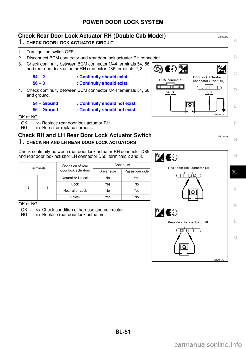
Check Rear Door Lock Actuator RH (Double Cab Model)EIS00D8D
1.CHECK DOOR LOCK ACTUATOR CIRCUIT
1. Turn ignition switch OFF.
2. Disconnect BCM connector and rear door lock actuator RH connector.
3. Check continuity between BCM connector M44 terminals 54, 56
and rear door lock actuator RH connector D85 terminals 2, 3.
4. Check continuity between BCM connector M44 terminals 54, 56
and ground.
OK or NG
OK >> Replace rear door lock actuator RH.
NG >> Repair or replace harness.
Check RH and LH Rear Door Lock Actuator SwitchEIS00DWX
1.CHECK RH AND LH REAR DOOR LOCK ACTUATORS
Check continuity between rear door lock actuator RH connector D85
and rear door lock actuator LH connector D65, terminals 2 and 3.
OK or NG
OK >> Check condition of harness and connector.
NG >> Replace rear door lock actuators.54 – 2 : Continuity should exist.
56 – 3 : Continuity should exist.
54 – Ground : Continuity should not exist.
56 – Ground : Continuity should not exist.
MIIB0888E
Te r m i n a l sCondition of rear
door lock actuatorsContinuity
Driver side Passenger side
23Neutral or Unlock No Yes
Lock Yes No
Neutral or Lock No Yes
Unlock Yes No
MIIB1048E