2005 NISSAN NAVARA lock
[x] Cancel search: lockPage 69 of 3171

TROUBLE DIAGNOSIS
AT-61
D
E
F
G
H
I
J
K
L
MA
B
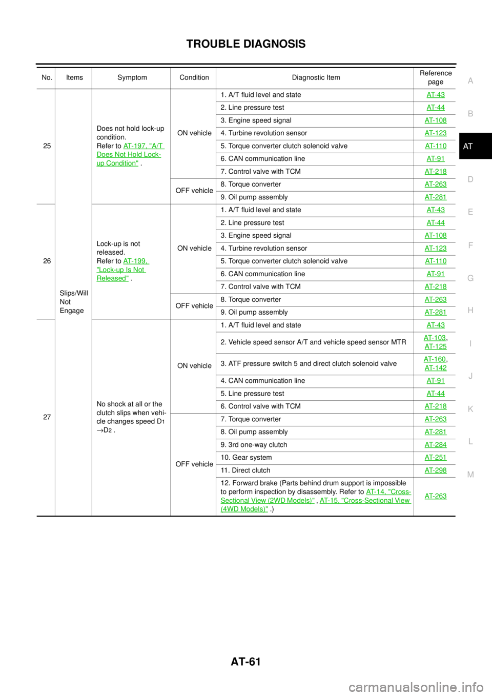
AT25
Slips/Will
Not
EngageDoes not hold lock-up
condition.
Refer toAT-197, "A/T
Does Not Hold Lock-
up Condition".ON vehicle1. A/T fluid level and stateAT- 4 3
2. Line pressure testAT- 4 4
3. Engine speed signalAT-108
4. Turbine revolution sensorAT-123
5. Torque converter clutch solenoid valveAT- 11 0
6. CAN communication lineAT- 9 1
7. Control valve with TCMAT-218
OFF vehicle8. Torque converterAT-2639. Oil pump assemblyAT-281
26Lock-up is not
released.
Refer toAT-199,
"Lock-up Is Not
Released".ON vehicle1. A/T fluid level and stateAT- 4 3
2. Line pressure testAT- 4 4
3. Engine speed signalAT-108
4. Turbine revolution sensorAT-123
5. Torque converter clutch solenoid valveAT- 11 0
6. CAN communication lineAT- 9 1
7. Control valve with TCMAT-218
OFF vehicle8. Torque converterAT-2639. Oil pump assemblyAT-281
27No shock at all or the
clutch slips when vehi-
cle changes speed D1
®D2.ON vehicle1. A/T fluid level and stateAT- 4 3
2. Vehicle speed sensor A/T and vehicle speed sensor MTRAT-103,
AT-125
3. ATF pressure switch 5 and direct clutch solenoid valveAT-160,
AT-142
4. CAN communication lineAT- 9 1
5. Line pressure testAT- 4 4
6. Control valve with TCMAT-218
OFF vehicle7. Torque converterAT-263
8. Oil pump assemblyAT-281
9. 3rd one-way clutchAT-284
10. Gear systemAT-251
11 . D i r e c t c l u t c hAT-298
12. Forward brake (Parts behind drum support is impossible
to perform inspection by disassembly. Refer toAT- 1 4 , "
Cross-
Sectional View (2WD Models)",AT- 1 5 , "Cross-Sectional View
(4WD Models)".)AT-263
No. Items Symptom Condition Diagnostic ItemReference
page
Page 76 of 3171

AT-68
TROUBLE DIAGNOSIS
40
Slips/Will
Not
EngageWhile accelerating in
4th, engine races or
slippage occurs.ON vehicle1. A/T fluid level and stateAT- 4 3
2. Line pressure testAT- 4 4
3. Accelerator pedal position sensorAT- 11 6
4. CAN communication lineAT- 9 1
5. ATF pressure switch 3 and input clutch solenoid valveAT- 1 5 8,
AT- 1 3 2
6. Control valve with TCMAT- 2 1 8
OFF vehicle7. Torque converterAT- 2 6 3
8. Oil pump assemblyAT- 2 8 1
9. Input clutchAT- 2 8 6
10. Gear systemAT- 2 5 1
11. High and low reverse clutchAT- 2 9 6
12. Direct clutchAT- 2 9 8
41While accelerating in
5th, engine races or
slippage occurs.ON vehicle1. A/T fluid level and stateAT- 4 3
2. Line pressure testAT- 4 4
3. Accelerator pedal position sensorAT- 11 6
4. CAN communication lineAT- 9 1
5. ATF pressure switch 1 and front brake solenoid valveAT- 1 5 6,
AT- 1 3 7
6. Control valve with TCMAT- 2 1 8
OFF vehicle7. Torque converterAT- 2 6 3
8. Oil pump assemblyAT- 2 8 1
9. Front brake (brake band)AT- 2 6 3
10. Input clutchAT- 2 8 6
11. Gear systemAT- 2 5 1
12. High and low reverse clutchAT- 2 9 6
42 Slips at lock-up.ON vehicle1. A/T fluid level and stateAT- 4 3
2. Line pressure testAT- 4 4
3. Engine speed signalAT- 1 0 8
4. Turbine revolution sensorAT- 1 2 3
5. Torque converter clutch solenoid valveAT- 11 0
6. CAN communication lineAT- 9 1
7. Control valve with TCMAT- 2 1 8
OFF vehicle8. Torque converterAT- 2 6 39. Oil pump assemblyAT- 2 8 1
No. Items Symptom Condition Diagnostic ItemReference
page
Page 79 of 3171

TROUBLE DIAGNOSIS
AT-71
D
E
F
G
H
I
J
K
L
MA
B
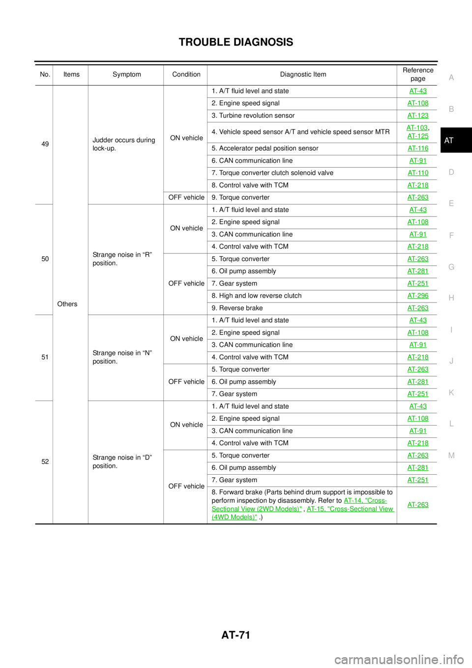
AT49
OthersJudder occurs during
lock-up.ON vehicle1. A/T fluid level and stateAT- 4 3
2. Engine speed signalAT-108
3. Turbine revolution sensorAT-123
4. Vehicle speed sensor A/T and vehicle speed sensor MTRAT-103,
AT-125
5. Accelerator pedal position sensorAT- 11 6
6. CAN communication lineAT- 9 1
7. Torque converter clutch solenoid valveAT- 11 0
8. Control valve with TCMAT-218
OFF vehicle 9. Torque converterAT-263
50Strange noise in “R”
position.ON vehicle1. A/T fluid level and stateAT- 4 3
2. Engine speed signalAT-108
3. CAN communication lineAT- 9 1
4. Control valve with TCMAT-218
OFF vehicle5. Torque converterAT-263
6. Oil pump assemblyAT-281
7. Gear systemAT-251
8. High and low reverse clutchAT-296
9. Reverse brakeAT-263
51Strange noise in “N”
position.ON vehicle1. A/T fluid level and stateAT- 4 3
2. Engine speed signalAT-108
3. CAN communication lineAT- 9 1
4. Control valve with TCMAT-218
OFF vehicle5. Torque converterAT-2636. Oil pump assemblyAT-281
7. Gear systemAT-251
52Strange noise in “D”
position.ON vehicle1. A/T fluid level and stateAT- 4 3
2. Engine speed signalAT-108
3. CAN communication lineAT- 9 1
4. Control valve with TCMAT-218
OFF vehicle5. Torque converterAT-263
6. Oil pump assemblyAT-281
7. Gear systemAT-251
8. Forward brake (Parts behind drum support is impossible to
perform inspection by disassembly. Refer toAT-14, "
Cross-
Sectional View (2WD Models)",AT- 1 5 , "Cross-Sectional View
(4WD Models)".)AT-263
No. Items Symptom Condition Diagnostic ItemReference
page
Page 85 of 3171

TROUBLE DIAGNOSIS
AT-77
D
E
F
G
H
I
J
K
L
MA
B
AT
CONSULT-II Function (A/T)ECS00FXA
CONSULT-II can display each diagnostic item using the diagnostic test modes shown following.
FUNCTION
CONSULT-II REFERENCE VALUE
NOTICE:
1. The CONSULT-II electrically displays shift timing and lock-up timing (that is, operation timing of each sole-
noid).
Check for time difference between actual shift timing and the CONSULT-II display. If the difference is
noticeable, mechanical parts (except solenoids, sensors, etc.) may be malfunctioning. Check mechanical
parts using applicable diagnostic procedures.
2. Shift schedule (which implies gear position) displayed on CONSULT-II and that indicated in Service Man-
ual may differ slightly. This occurs because of the following reasons:
–Actual shift schedule has more or less tolerance or allowance,
–Shift schedule indicated in Service Manual refers to the point where shifts start, and
–Gear position displayed on CONSULT-II indicates the point where shifts are completed.
3. Display of solenoid valves on CONSULT-II changes at the start of shifting, while gear position is displayed
upon completion of shifting (which is computed by TCM).
Diagnostic test mode Function Reference page
Self-diagnostic results Self-diagnostic results can be read and erased quickly.AT- 8 0
Data monitor Input/Output data in the ECU can be read.AT- 8 3
CAN diagnostic support
monitorThe results of transmit/receive diagnosis of CAN communication can be read.AT- 8 6
Function testConducted by CONSULT-II instead of a technician to determine whether each system
is “OK” or “NG”.—
DTC work support Select the operating condition to confirm Diagnostic Trouble Codes.AT- 8 6
ECU part number ECU part number can be read. —
Item name Condition Display value (Approx.)
VHCL/S SE-A/T
During drivingApproximately matches the speed-
ometer reading.
VHCL/S SE-MTR
ACCELE POSIReleased accelerator pedal. 0.0/8
Fully depressed accelerator pedal. 8.0/8
CLSD THL POSReleased accelerator pedal. ON
Fully depressed accelerator pedal. OFF
W/O THL POSFully depressed accelerator pedal. ON
Released accelerator pedal. OFF
BRAKE SWDepressed brake pedal. ON
Released brake pedal. OFF
ENGINE SPEED Engine runningClosely matches the tachometer
reading.
TURBINE REV During driving (lock-up ON)Approximately matches the engine
speed.
ATFTEMPSE1
0°C(32°F)-20°C(68°F)-80°C (176°F)3.3 - 2.7 - 0.9 V
ATFTEMPSE23.3 - 2.5 - 0.7 V
TCC SOLENOID When perform lock-up 0.4 - 0.6 A
LINE PRES SOL During driving 0.2 - 0.6 A
FR/B SOLENOIDFront brake engaged. Refer toAT- 1 7
. 0.6 - 0.8 A
Front brake disengaged. Refer toAT- 1 7
.0-0.05A
Page 88 of 3171

AT-80
TROUBLE DIAGNOSIS
SELF-DIAGNOSTIC RESULT MODE
Operation Procedure
After performing self-diagnosis, place check marks for results on theAT-38, "DIAGNOSTIC WORKSHEET".
Reference pages are provided following the items.
1. PerformAT- 7 9 , "
CONSULT-II SETTING PROCEDURE".
2. Touch “SELF-DIAG RESULTS”.
Display shows malfunction experienced since the last erasing
operation.
Display Items List
X: Applicable, —: Not applicable
BCIA0031E
Items (CONSULT-II
screen terms)Malfunction is detected when...TCM self-diagnosis
Reference page
DTC
CAN COMM CIRCUIT
lWhen a malfunction is detected in CAN communications U1000AT- 9 1
STARTER RELAY/
CIRC
lIf this signal is ON other than in “P” or “N” position, this is
judged to be a malfunction.
(And if it is OFF in “P” or “N” position, this too is judged to
be a malfunction.)P0615AT- 9 4
TCMlTCM is malfunctioning. P0700AT- 9 8
PNP SW/CIRC
lPNP switch 1-4 signals input with impossible pattern
l“P” position is detected from “N” position without any other
position being detected in between.P0705AT- 9 9
VEH SPD SEN/CIR AT
lSignal from vehicle speed sensor A/T (Revolution sensor)
not input due to cut line or the like
lUnexpected signal input during running
lAfter ignition switch is turned ON, unexpected signal input
from vehicle speed sensor MTR before the vehicle starts
movingP0720AT- 1 0 3
ENGINE SPEED SIGlTCM does not receive the CAN communication signal from
the ECM.P0725AT- 1 0 8
TCC SOLENOID/CIRClNormal voltage not applied to solenoid due to cut line,
short, or the likeP0740AT- 11 0
A/T TCC S/V FNCTN
lA/T cannot perform lock-up even if electrical circuit is good.
lTCM detects as irregular by comparing difference value
with slip rotation.P0744AT- 11 2
L/PRESS SOL/CIRC
lNormal voltage not applied to solenoid due to cut line,
short, or the like
lTCM detects as irregular by comparing target value with
monitor value.P0745AT- 11 4
TP SEN/CIRC A/TlTCM does not receive the proper accelerator pedal posi-
tion signals (input by CAN communication) from ECM.P1705AT- 11 6
ATF TEMP SEN/CIRClDuring running, the ATF temperature sensor signal voltage
is excessively high or lowP1710AT- 11 8
TURBINE REV S/CIRC
lTCM does not receive the proper voltage signal from the
sensor.
lTCM detects an irregularity only at position of 4th gear for
turbine revolution sensor 2.P1716AT- 1 2 3
Page 89 of 3171

TROUBLE DIAGNOSIS
AT-81
D
E
F
G
H
I
J
K
L
MA
B
AT
VEH SPD SE/CIR-MTR
lSignal (CAN communication) from vehicle speed sensor
MTR not input due to cut line or the like
lUnexpected signal input during runningP1721AT- 1 2 5
A/T INTERLOCK
lExcept during shift change, the gear position and ATF
pressure switch states are monitored and comparative
judgement made.P1730AT- 1 2 7
A/T 1ST E/BRAKING
lEach ATF pressure switch and solenoid current is moni-
tored and if a pattern is detected having engine braking 1st
gear other than in the “1” position, a malfunction is
detected.P1731AT- 1 3 0
I/C SOLENOID/CIRC
lNormal voltage not applied to solenoid due to functional
malfunction, cut line, short, or the like
lTCM detects as irregular by comparing target value with
monitor value.P1752AT- 1 3 2
I/C SOLENOID FNCTN
lTCM detects that actual gear ratio is irregular, and relation
between gear position and condition of ATF pressure
switch 3 is irregular during depressing accelerator pedal.
(Other than during shift change)
lTCM detects that relation between gear position and condi-
tion of ATF pressure switch 3 is irregular during releasing
accelerator pedal. (Other than during shift change)P1754AT- 1 3 4
FR/B SOLENOID/CIRC
lNormal voltage not applied to solenoid due to functional
malfunction, cut line, short, or the like
lTCM detects as irregular by comparing target value with
monitor value.P1757AT- 1 3 7
FR/B SOLENOID FNCT
lTCM detects that actual gear ratio is irregular, and relation
between gear position and condition of ATF pressure
switch 1 is irregular during depressing accelerator pedal.
(Other than during shift change)
lTCM detects that relation between gear position and condi-
tion of ATF pressure switch 1 is irregular during releasing
accelerator pedal. (Other than during shift change)P1759AT- 1 3 9
D/C SOLENOID/CIRC
lNormal voltage not applied to solenoid due to cut line,
short, or the like
lTCM detects as irregular by comparing target value with
monitor value.P1762AT- 1 4 2
D/C SOLENOID
FNCTN
lTCM detects that actual gear ratio is irregular, and relation
between gear position and condition of ATF pressure
switch 5 is irregular during depressing accelerator pedal.
(Other than during shift change)
lTCM detects that relation between gear position and condi-
tion of ATF pressure switch 5 is irregular during releasing
accelerator pedal. (Other than during shift change)P1764AT- 1 4 4
HLR/C SOL/CIRC
lNormal voltage not applied to solenoid due to functional
malfunction, cut line, short, or the like
lTCM detects as irregular by comparing target value with
monitor value.P1767AT- 1 4 7
HLR/C SOL FNCTN
lTCM detects that actual gear ratio is irregular, and relation
between gear position and condition of ATF pressure
switch 6 is irregular during depressing accelerator pedal.
(Other than during shift change)
lTCM detects that relation between gear position and condi-
tion of ATF pressure switch 6 is irregular during releasing
accelerator pedal. (Other than during shift change)P1769AT- 1 4 9
Items (CONSULT-II
screen terms)Malfunction is detected when...TCM self-diagnosis
Reference page
DTC
Page 96 of 3171

AT-88
TROUBLE DIAGNOSIS
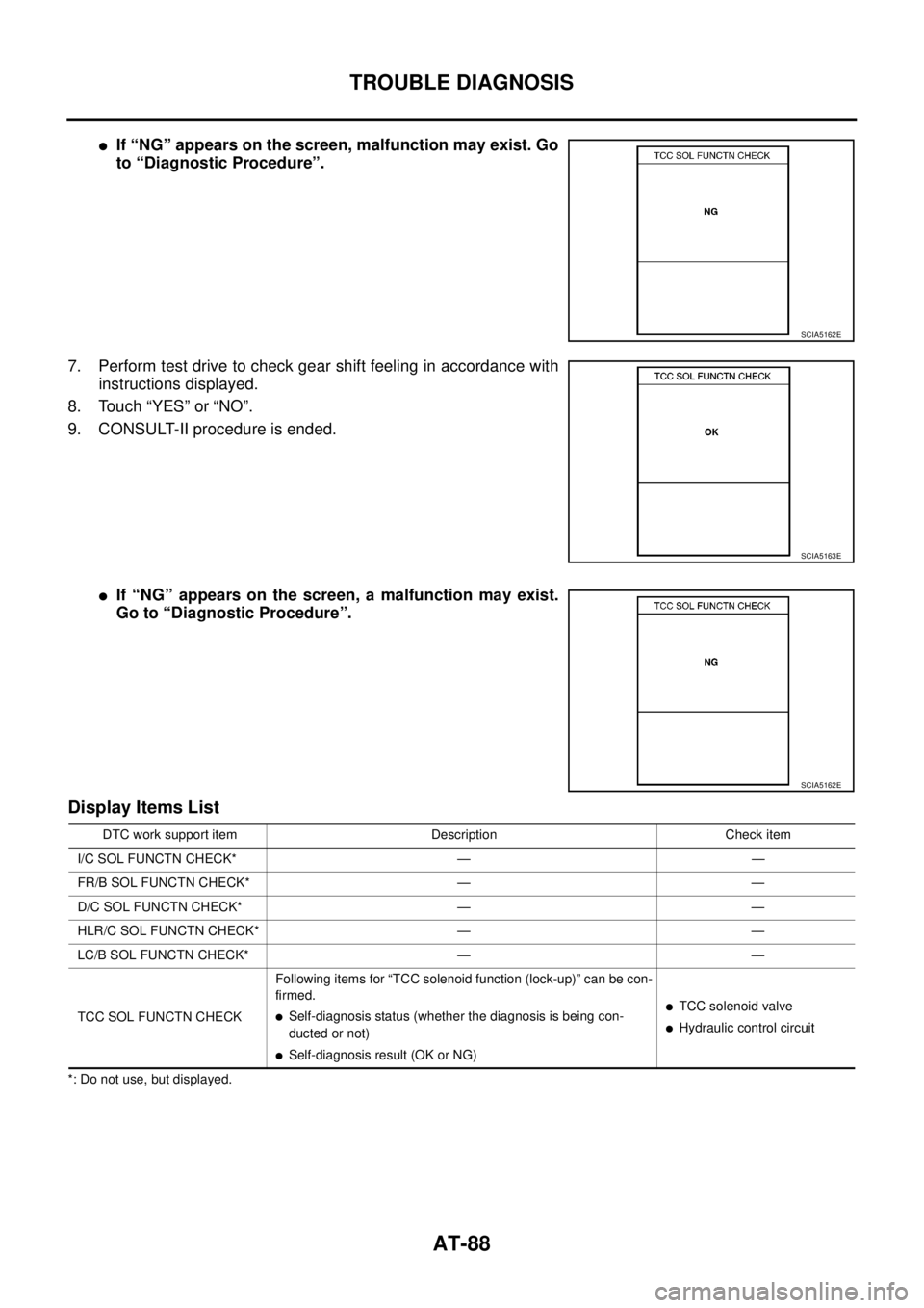
lIf “NG” appears on the screen, malfunction may exist. Go
to “Diagnostic Procedure”.
7. Perform test drive to check gear shift feeling in accordance with
instructions displayed.
8. Touch “YES” or “NO”.
9. CONSULT-II procedure is ended.
lIf “NG” appears on the screen, a malfunction may exist.
Go to “Diagnostic Procedure”.
Display Items List
*: Do not use, but displayed.
SCIA5162E
SCIA5163E
SCIA5162E
DTC work support item Description Check item
I/C SOL FUNCTN CHECK* — —
FR/B SOL FUNCTN CHECK* — —
D/C SOL FUNCTN CHECK* — —
HLR/C SOL FUNCTN CHECK* — —
LC/B SOL FUNCTN CHECK* — —
TCC SOL FUNCTN CHECKFollowing items for “TCC solenoid function (lock-up)” can be con-
firmed.
lSelf-diagnosis status (whether the diagnosis is being con-
ducted or not)
lSelf-diagnosis result (OK or NG)
lTCC solenoid valve
lHydraulic control circuit
Page 97 of 3171

TROUBLE DIAGNOSIS
AT-89
D
E
F
G
H
I
J
K
L
MA
B
AT
Diagnostic Procedure Without CONSULT-IIECS00FXB
TCM SELF-DIAGNOSTIC PROCEDURE (WITHOUT CONSULT-II)
Description
In the unlikely event of a malfunction in the electrical system, when the ignition switch is switched ON, the OD
OFF indicator lamp lights up for 2 seconds. If there is no malfunction, when the ignition switch is turned ON,
the indicator lamp lights up for 2 seconds. As a method for locating the suspect circuit, when the self-diagnos-
tics start signal is input, the memory for the malfunction location is output and OD OFF indicator lamp flashes
to display the corresponding DTC.
Diagnostic Procedure
1.CHECK OD OFF INDICATOR LAMP
1. Start the engine with selector lever in “P” position. Warm engine to normal operating temperature.
2. Turn ignition switch ON and OFF at least twice, then leave it in the OFF position.
3. Wait 10 seconds.
4. Turn ignition switch ON. (Do not start engine.)
Does OD OFF indicator lamp come on for about 2 seconds?
YES >> GO TO 2.
NO >> GO TOAT- 1 7 7 , "
OD OFF Indicator Lamp Does Not Come On".
2.JUDGEMENT PROCEDURE
1. Turn ignition switch OFF.
2. Keep pressing shift lock release button.
3. Move selector lever from “P” to “D” position.
4. Release accelerator pedal. (Set the closed throttle position signal ON.)
5. Depress brake pedal. (Stop lamp switch signal ON.)
6. Turn ignition switch ON.
7. Wait 3 seconds.
8. Move selector lever from “D” to “3” position.
9. Release brake pedal. (Stop lamp switch signal OFF.)
10. Move selector lever from “3” to “2” position.
11. Depress brake pedal. (Stop lamp switch signal ON.)
12. Release brake pedal. (Stop lamp switch signal OFF.)
13. Depress accelerator pedal fully and release it.
>> GO TO 3.
3.CHECK SELF-DIAGNOSIS CODE
Check OD OFF indicator lamp. Refer toAT-90, "
Judgement Self-diagnosis Code".
If the system does not go into self-diagnosis. Refer toAT-99, "
DTC P0705 PARK/NEUTRAL POSITION
SWITCH",AT- 1 6 8 , "CLOSED THROTTLE POSITION AND WIDE OPEN THROTTLE POSITION CIRCUIT",
AT- 1 6 9 , "
BRAKE SIGNAL CIRCUIT".
>>DIAGNOSIS END