2005 NISSAN NAVARA control unit
[x] Cancel search: control unitPage 3058 of 3171
TROUBLE DIAGNOSIS FOR SYMPTOMS
TF-91
C
E
F
G
H
I
J
K
L
MA
B
TF
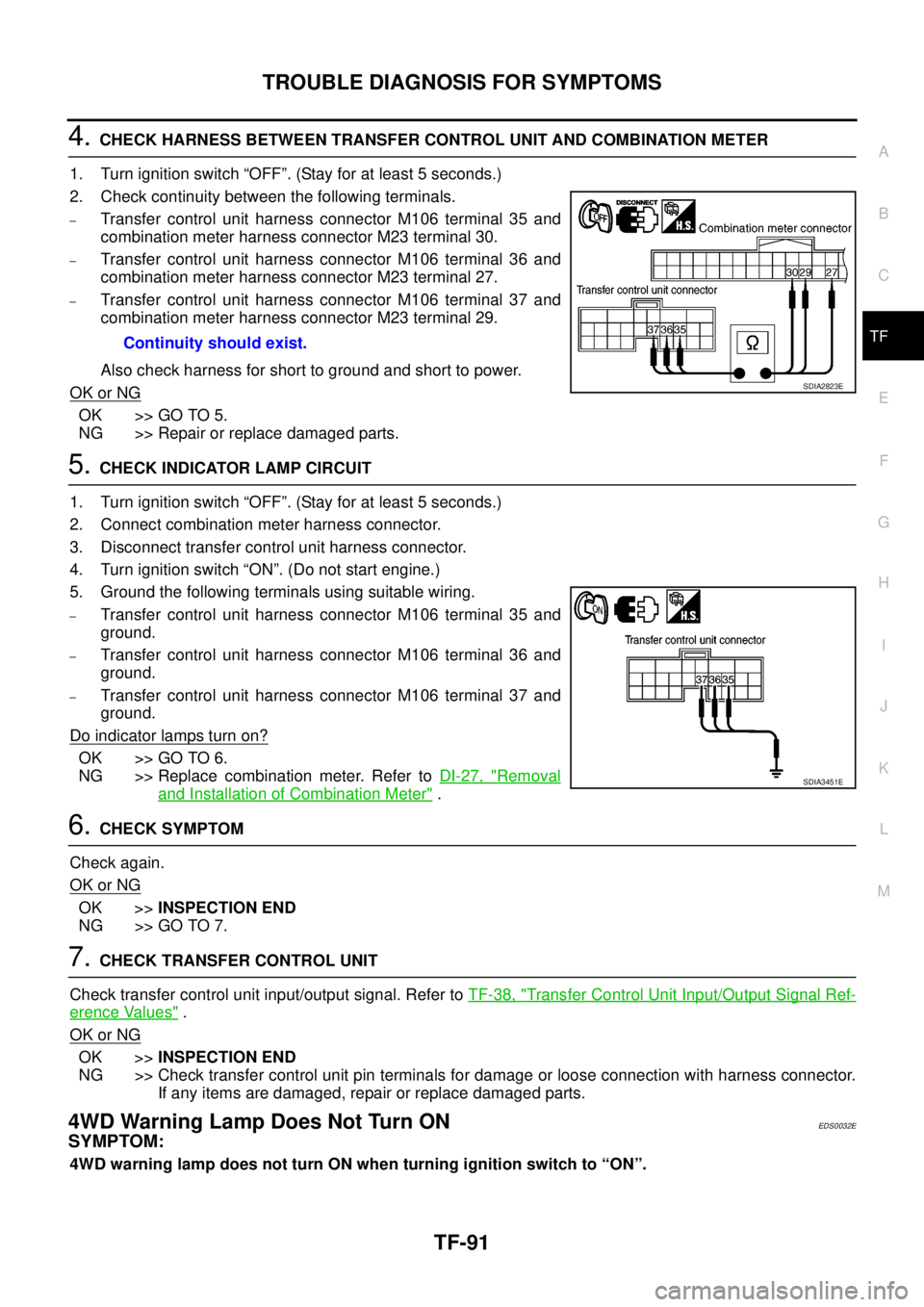
4.CHECK HARNESS BETWEEN TRANSFER CONTROL UNIT AND COMBINATION METER
1. Turn ignition switch “OFF”. (Stay for at least 5 seconds.)
2. Check continuity between the following terminals.
–Transfer control unit harness connector M106 terminal 35 and
combination meter harness connector M23 terminal 30.
–Transfer control unit harness connector M106 terminal 36 and
combination meter harness connector M23 terminal 27.
–Transfer control unit harness connector M106 terminal 37 and
combination meter harness connector M23 terminal 29.
Also check harness for short to ground and short to power.
OK or NG
OK >> GO TO 5.
NG >> Repair or replace damaged parts.
5.CHECK INDICATOR LAMP CIRCUIT
1. Turn ignition switch “OFF”. (Stay for at least 5 seconds.)
2. Connect combination meter harness connector.
3. Disconnect transfer control unit harness connector.
4. Turn ignition switch “ON”. (Do not start engine.)
5. Ground the following terminals using suitable wiring.
–Transfer control unit harness connector M106 terminal 35 and
ground.
–Transfer control unit harness connector M106 terminal 36 and
ground.
–Transfer control unit harness connector M106 terminal 37 and
ground.
Do indicator lamps turn on?
OK >> GO TO 6.
NG >> Replace combination meter. Refer toDI-27, "
Removal
and Installation of Combination Meter".
6.CHECK SYMPTOM
Check again.
OK or NG
OK >>INSPECTION END
NG >> GO TO 7.
7.CHECK TRANSFER CONTROL UNIT
Check transfer control unit input/output signal. Refer toTF-38, "
Transfer Control Unit Input/Output Signal Ref-
erence Values".
OK or NG
OK >>INSPECTION END
NG >> Check transfer control unit pin terminals for damage or loose connection with harness connector.
If any items are damaged, repair or replace damaged parts.
4WD Warning Lamp Does Not Turn ONEDS0032E
SYMPTOM:
4WD warning lamp does not turn ON when turning ignition switch to “ON”.Continuity should exist.
SDIA2823E
SDIA3451E
Page 3059 of 3171
TF-92
TROUBLE DIAGNOSIS FOR SYMPTOMS
DIAGNOSTIC PROCEDURE
1.CHECK TRANSFER CONTROL UNIT POWER SUPPLY CIRCUIT
1. Turn ignition switch “OFF”. (Stay for at least 5 seconds.)
2. Disconnect transfer control unit harness connector.
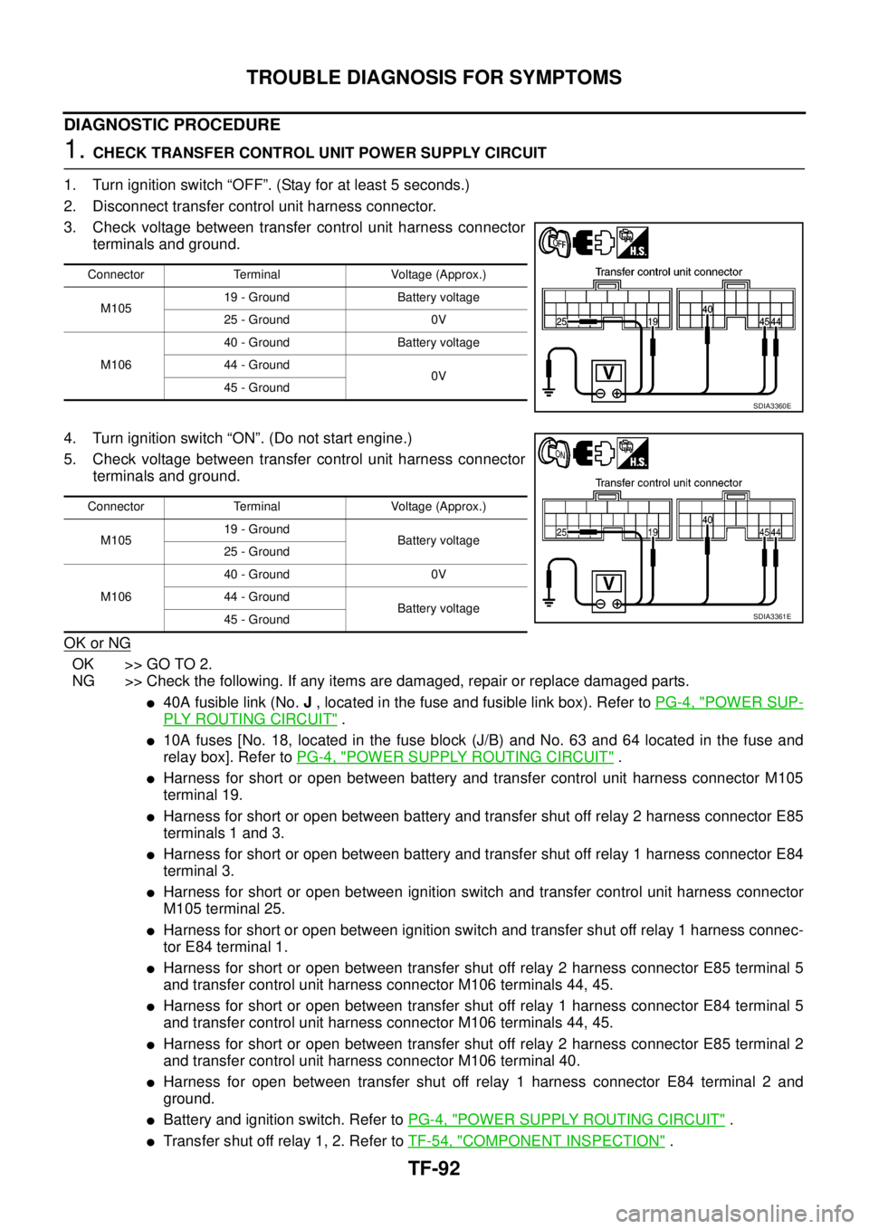
3. Check voltage between transfer control unit harness connector
terminals and ground.
4. Turn ignition switch “ON”. (Do not start engine.)
5. Check voltage between transfer control unit harness connector
terminals and ground.
OK or NG
OK >> GO TO 2.
NG >> Check the following. If any items are damaged, repair or replace damaged parts.
l40A fusible link (No.J, located in the fuse and fusible link box). Refer toPG-4, "POWER SUP-
PLY ROUTING CIRCUIT".
l10A fuses [No. 18, located in the fuse block (J/B) and No. 63 and 64 located in the fuse and
relay box]. Refer toPG-4, "
POWER SUPPLY ROUTING CIRCUIT".
lHarness for short or open between battery and transfer control unit harness connector M105
terminal 19.
lHarness for short or open between battery and transfer shut off relay 2 harness connector E85
terminals 1 and 3.
lHarness for short or open between battery and transfer shut off relay 1 harness connector E84
terminal 3.
lHarness for short or open between ignition switch and transfer control unit harness connector
M105 terminal 25.
lHarness for short or open between ignition switch and transfer shut off relay 1 harness connec-
tor E84 terminal 1.
lHarness for short or open between transfer shut off relay 2 harness connector E85 terminal 5
and transfer control unit harness connector M106 terminals 44, 45.
lHarness for short or open between transfer shut off relay 1 harness connector E84 terminal 5
and transfer control unit harness connector M106 terminals 44, 45.
lHarness for short or open between transfer shut off relay 2 harness connector E85 terminal 2
and transfer control unit harness connector M106 terminal 40.
lHarness for open between transfer shut off relay 1 harness connector E84 terminal 2 and
ground.
lBattery and ignition switch. Refer toPG-4, "POWER SUPPLY ROUTING CIRCUIT".
lTransfer shut off relay 1, 2. Refer toTF-54, "COMPONENT INSPECTION".
Connector Terminal Voltage (Approx.)
M10519 - Ground Battery voltage
25 - Ground 0V
M10640 - Ground Battery voltage
44 - Ground
0V
45 - Ground
SDIA3360E
Connector Terminal Voltage (Approx.)
M10519 - Ground
Battery voltage
25 - Ground
M10640 - Ground 0V
44 - Ground
Battery voltage
45 - Ground
SDIA3361E
Page 3060 of 3171
TROUBLE DIAGNOSIS FOR SYMPTOMS
TF-93
C
E
F
G
H
I
J
K
L
MA
B
TF
2.CHECK TRANSFER CONTROL UNIT GROUND CIRCUIT
1. Turn ignition switch “OFF”. (Stay for at least 5 seconds.)
2. Disconnect transfer control unit harness connectors.
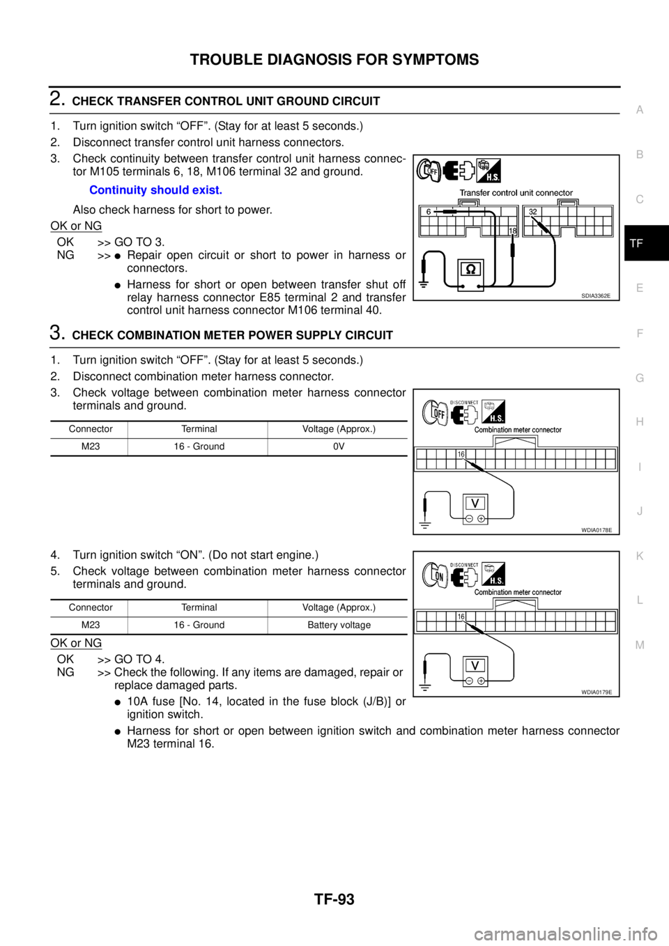
3. Check continuity between transfer control unit harness connec-
tor M105 terminals 6, 18, M106 terminal 32 and ground.
Also check harness for short to power.
OK or NG
OK >> GO TO 3.
NG >>
lRepair open circuit or short to power in harness or
connectors.
lHarness for short or open between transfer shut off
relay harness connector E85 terminal 2 and transfer
control unit harness connector M106 terminal 40.
3.CHECK COMBINATION METER POWER SUPPLY CIRCUIT
1. Turn ignition switch “OFF”. (Stay for at least 5 seconds.)
2. Disconnect combination meter harness connector.
3. Check voltage between combination meter harness connector
terminals and ground.
4. Turn ignition switch “ON”. (Do not start engine.)
5. Check voltage between combination meter harness connector
terminals and ground.
OK or NG
OK >> GO TO 4.
NG >> Check the following. If any items are damaged, repair or
replace damaged parts.
l10A fuse [No. 14, located in the fuse block (J/B)] or
ignition switch.
lHarness for short or open between ignition switch and combination meter harness connector
M23 terminal 16. Continuity should exist.
SDIA3362E
Connector Terminal Voltage (Approx.)
M23 16 - Ground 0V
WDIA0178E
Connector Terminal Voltage (Approx.)
M23 16 - Ground Battery voltage
WDIA0179E
Page 3061 of 3171
TF-94
TROUBLE DIAGNOSIS FOR SYMPTOMS
4.CHECK HARNESS BETWEEN TRANSFER CONTROL UNIT AND COMBINATION METER
1. Turn ignition switch “OFF”. (Stay for at least 5 seconds.)
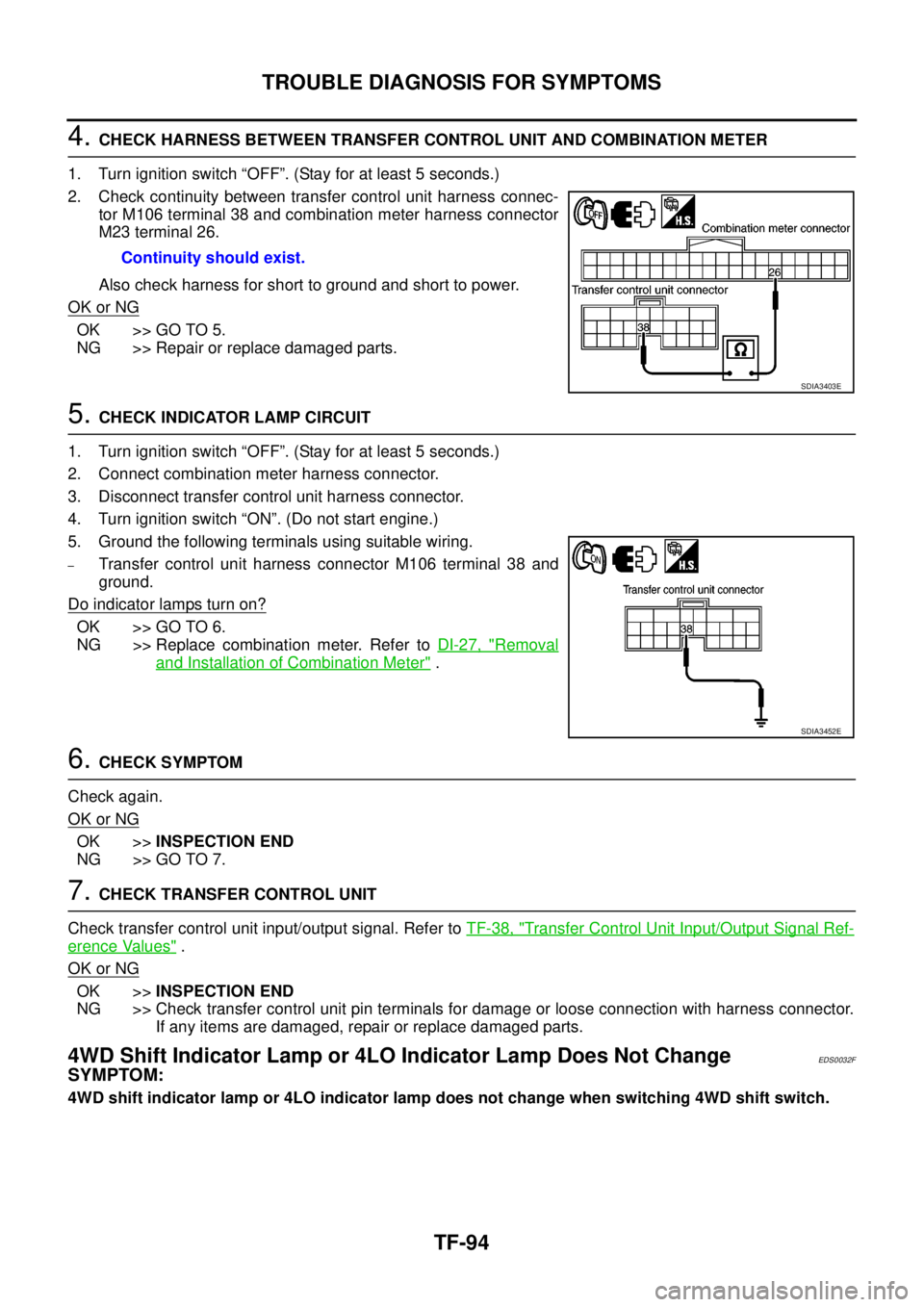
2. Check continuity between transfer control unit harness connec-
tor M106 terminal 38 and combination meter harness connector
M23 terminal 26.
Also check harness for short to ground and short to power.
OK or NG
OK >> GO TO 5.
NG >> Repair or replace damaged parts.
5.CHECK INDICATOR LAMP CIRCUIT
1. Turn ignition switch “OFF”. (Stay for at least 5 seconds.)
2. Connect combination meter harness connector.
3. Disconnect transfer control unit harness connector.
4. Turn ignition switch “ON”. (Do not start engine.)
5. Ground the following terminals using suitable wiring.
–Transfer control unit harness connector M106 terminal 38 and
ground.
Do indicator lamps turn on?
OK >> GO TO 6.
NG >> Replace combination meter. Refer toDI-27, "
Removal
and Installation of Combination Meter".
6.CHECK SYMPTOM
Check again.
OK or NG
OK >>INSPECTION END
NG >> GO TO 7.
7.CHECK TRANSFER CONTROL UNIT
Check transfer control unit input/output signal. Refer toTF-38, "
Transfer Control Unit Input/Output Signal Ref-
erence Values".
OK or NG
OK >>INSPECTION END
NG >> Check transfer control unit pin terminals for damage or loose connection with harness connector.
If any items are damaged, repair or replace damaged parts.
4WD Shift Indicator Lamp or 4LO Indicator Lamp Does Not ChangeEDS0032F
SYMPTOM:
4WD shift indicator lamp or 4LO indicator lamp does not change when switching 4WD shift switch.Continuity should exist.
SDIA3403E
SDIA3452E
Page 3062 of 3171
TROUBLE DIAGNOSIS FOR SYMPTOMS
TF-95
C
E
F
G
H
I
J
K
L
MA
B
TF
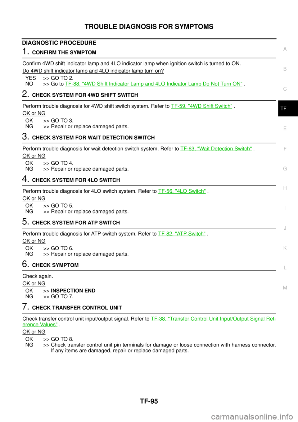
DIAGNOSTIC PROCEDURE
1.CONFIRM THE SYMPTOM
Confirm 4WD shift indicator lamp and 4LO indicator lamp when ignition switch is turned to ON.
Do 4WD shift indicator lamp and 4LO indicator lamp turn on?
YES >> GO TO 2.
NO >> Go toTF-88, "
4WD Shift Indicator Lamp and 4LO Indicator Lamp Do Not Turn ON".
2.CHECK SYSTEM FOR 4WD SHIFT SWITCH
Perform trouble diagnosis for 4WD shift switch system. Refer toTF-59, "
4WD Shift Switch".
OK or NG
OK >> GO TO 3.
NG >> Repair or replace damaged parts.
3.CHECK SYSTEM FOR WAIT DETECTION SWITCH
Perform trouble diagnosis for wait detection switch system. Refer toTF-63, "
Wait Detection Switch".
OK or NG
OK >> GO TO 4.
NG >> Repair or replace damaged parts.
4.CHECK SYSTEM FOR 4LO SWITCH
Perform trouble diagnosis for 4LO switch system. Refer toTF-56, "
4LO Switch".
OK or NG
OK >> GO TO 5.
NG >> Repair or replace damaged parts.
5.CHECK SYSTEM FOR ATP SWITCH
Perform trouble diagnosis for ATP switch system. Refer toTF-82, "
AT P S w i t c h".
OK or NG
OK >> GO TO 6.
NG >> Repair or replace damaged parts.
6.CHECK SYMPTOM
Check again.
OK or NG
OK >>INSPECTION END
NG >> GO TO 7.
7.CHECK TRANSFER CONTROL UNIT
Check transfer control unit input/output signal. Refer toTF-38, "
Transfer Control Unit Input/Output Signal Ref-
erence Values".
OK or NG
OK >> GO TO 8.
NG >> Check transfer control unit pin terminals for damage or loose connection with harness connector.
If any items are damaged, repair or replace damaged parts.
Page 3064 of 3171
TROUBLE DIAGNOSIS FOR SYMPTOMS
TF-97
C
E
F
G
H
I
J
K
L
MA
B
TF
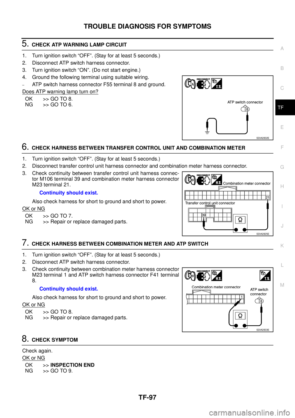
5.CHECK ATP WARNING LAMP CIRCUIT
1. Turn ignition switch “OFF”. (Stay for at least 5 seconds.)
2. Disconnect ATP switch harness connector.
3. Turn ignition switch “ON”. (Do not start engine.)
4. Ground the following terminal using suitable wiring.
–ATP switch harness connector F55 terminal 8 and ground.
Does ATP warning lamp turn on?
OK >> GO TO 8.
NG >> GO TO 6.
6.CHECK HARNESS BETWEEN TRANSFER CONTROL UNIT AND COMBINATION METER
1. Turn ignition switch “OFF”. (Stay for at least 5 seconds.)
2. Disconnect transfer control unit harness connector and combination meter harness connector.
3. Check continuity between transfer control unit harness connec-
tor M106 terminal 39 and combination meter harness connector
M23 terminal 21.
Also check harness for short to ground and short to power.
OK or NG
OK >> GO TO 7.
NG >> Repair or replace damaged parts.
7.CHECK HARNESS BETWEEN COMBINATION METER AND ATP SWITCH
1. Turn ignition switch “OFF”. (Stay for at least 5 seconds.)
2. Disconnect ATP switch harness connector.
3. Check continuity between combination meter harness connector
M23 terminal 1 and ATP switch harness connector F41 terminal
8.
Also check harness for short to ground and short to power.
OK or NG
OK >> GO TO 8.
NG >> Repair or replace damaged parts.
8.CHECK SYMPTOM
Check again.
OK or NG
OK >>INSPECTION END
NG >> GO TO 9.
SDIA2832E
Continuity should exist.
SDIA2825E
Continuity should exist.
SDIA2833E
Page 3065 of 3171
TF-98
TROUBLE DIAGNOSIS FOR SYMPTOMS
9.CHECK TRANSFER CONTROL UNIT
Check transfer control unit input/output signal. Refer toTF-38, "
Transfer Control Unit Input/Output Signal Ref-
erence Values".
OK or NG
OK >> GO TO 10.
NG >> Check transfer control unit pin terminals for damage or loose connection with harness connector.
If any items are damaged, repair or replace damaged parts.
10.CHECK TRANSFER INNER PARTS
1. Disassemble transfer assembly. Refer toTF-112, "
Disassembly and Assembly".
2. Check transfer inner parts.
OK or NG
OK >>INSPECTION END
NG >> Repair or replace damaged parts.
4WD Shift Indicator Lamp Repeats FlashingEDS0032H
SYMPTOM:
4WD shift indicator lamp keeps flashing.
DIAGNOSTIC PROCEDURE
1.CONFIRM THE SYMPTOM
1. Set4WDshiftswitchto“2WD”.
2. Move vehicle forward and backward, or drive straight increasing or decreasing under 20 km/h (12 MPH).
Dose 4WD shift indicator lamp keep flashing?
YES >> GO TO 2.
NO >>INSPECTION END
2.CHECK SYSTEM FOR WAIT DETECTION SWITCH
Perform trouble diagnosis for wait detection switch system. Refer toTF-63, "
Wait Detection Switch".
OK or NG
OK >> GO TO 3.
NG >> Repair or replace damaged parts.
3.CHECK SYSTEM FOR 4LO SWITCH
Perform trouble diagnosis for 4LO switch system. Refer toTF-56, "
4LO Switch".
OK or NG
OK >> GO TO 4.
NG >> Repair or replace damaged parts.
4.CHECK SYMPTOM
Check again.
OK or NG
OK >>INSPECTION END
NG >> GO TO 5.
Page 3066 of 3171
TROUBLE DIAGNOSIS FOR SYMPTOMS
TF-99
C
E
F
G
H
I
J
K
L
MA
B
TF
5.CHECK TRANSFER CONTROL UNIT
Check transfer control unit input/output signal. Refer toTF-38, "
Transfer Control Unit Input/Output Signal Ref-
erence Values".
OK or NG
OK >> GO TO 6.
NG >> Check transfer control unit pin terminals for damage or loose connection with harness connector.
If any items are damaged, repair or replace damaged parts.
6.CHECK TRANSFER INNER PARTS
1. Disassemble transfer assembly. Refer toTF-112, "
Disassembly and Assembly".
2. Check transfer inner parts.
OK or NG
OK >>INSPECTION END
NG >> Repair or replace damaged parts.
4WD Warning Lamp Flashes SlowlyEDS0032I
SYMPTOM:
While driving, 4WD warning lamp flashes slowly. (Continues to flash until turning ignition switch OFF.)
NOTE:
Slow flashing: 1 time/2 seconds
DIAGNOSTIC PROCEDURE
1.CHECK TIRES
Check the following.
lTire pressure
lWear condition
lLongitudinal tire size (There is no difference between longitudinal tires.)
OK or NG
OK >> GO TO 2.
NG >> Repair or replace damaged parts.
2.CHECK SYMPTOM
Check again.
OK or NG
OK >>INSPECTION END
NG >> GO TO 3.
3.CHECK TRANSFER CONTROL UNIT
Check transfer control unit input/output signal. Refer toTF-38, "
Transfer Control Unit Input/Output Signal Ref-
erence Values".
OK or NG
OK >>INSPECTION END
NG >> Check transfer control unit pin terminals for damage or loose connection with harness connector.
If any items are damaged, repair or replace damaged parts.