Page 3067 of 3171
TF-100
TRANSFER CONTROL UNIT
TRANSFER CONTROL UNIT
PFP:33084
Removal and InstallationEDS0032J
REMOVAL
1. Switch 4WD shift switch to 2WD and set transfer assembly to 2WD.
CAUTION:
When removal transfer control unit, transfer state must be at 2WD or AUTO.
2. Turn the ignition switch OFF and disconnect the battery cables.
3. Remove the lower instrument panel LH (LHD models) or lower instrument panel RH (RHD models). Refer
toIP-13, "
LOWER INSTRUMENT PANEL LH"(LHD models) orIP-13, "LOWER INSTRUMENT PANEL
LH"(RHD models).
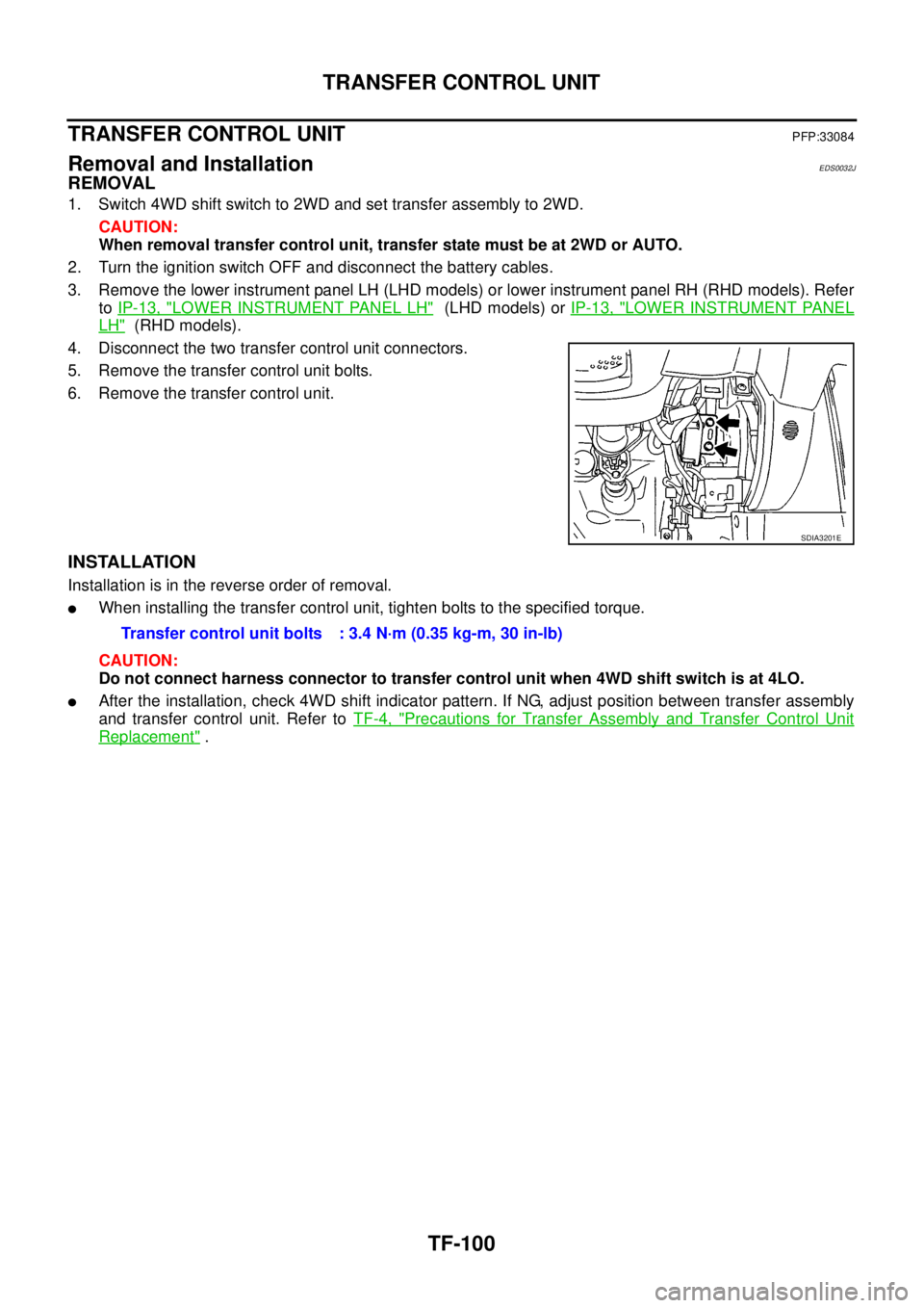
4. Disconnect the two transfer control unit connectors.
5. Remove the transfer control unit bolts.
6. Remove the transfer control unit.
INSTALLATION
Installation is in the reverse order of removal.
lWhen installing the transfer control unit, tighten bolts to the specified torque.
CAUTION:
Do not connect harness connector to transfer control unit when 4WD shift switch is at 4LO.
lAfter the installation, check 4WD shift indicator pattern. If NG, adjust position between transfer assembly
and transfer control unit. Refer toTF-4, "
Precautions for Transfer Assembly and Transfer Control Unit
Replacement".
SDIA3201E
Transfer control unit bolts : 3.4 N·m (0.35 kg-m, 30 in-lb)
Page 3073 of 3171
TF-106
TRANSFER CONTROL DEVICE
c. Tighten the bolts to the specified torque. Refer toTF-112, "COM-
PONENTS".
3. Install the breather hose to the transfer control device.
4. Connect the transfer control device connector.
5. After the installation, check the 4WD shift indicator pattern. If
NG, adjust the position between the transfer assembly and
transfer control unit. Refer toTF-4, "
Precautions for Transfer
Assembly and Transfer Control Unit Replacement".
SDIA2212E
Page 3079 of 3171
TF-112
TRANSFER ASSEMBLY
INSTALLATION
Note the following, and install in the reverse order of removal.
lTighten the bolts to specification.
lAfter the installation, check the transfer fluid level and fluid leak-
age. Refer toTF-12, "
FLUID LEAKAGE AND FLUID LEVEL".
lAfter filling, start the engine for one minute. Then stop the
engine and recheck the transfer fluid.
lAfter the installation, check the 4WD shift indicator pattern. If
NG, adjust the position between the transfer assembly and
transfer control unit. Refer toTF-4, "
Precautions for Transfer
Assembly and Transfer Control Unit Replacement".
Disassembly and AssemblyEDS0032P
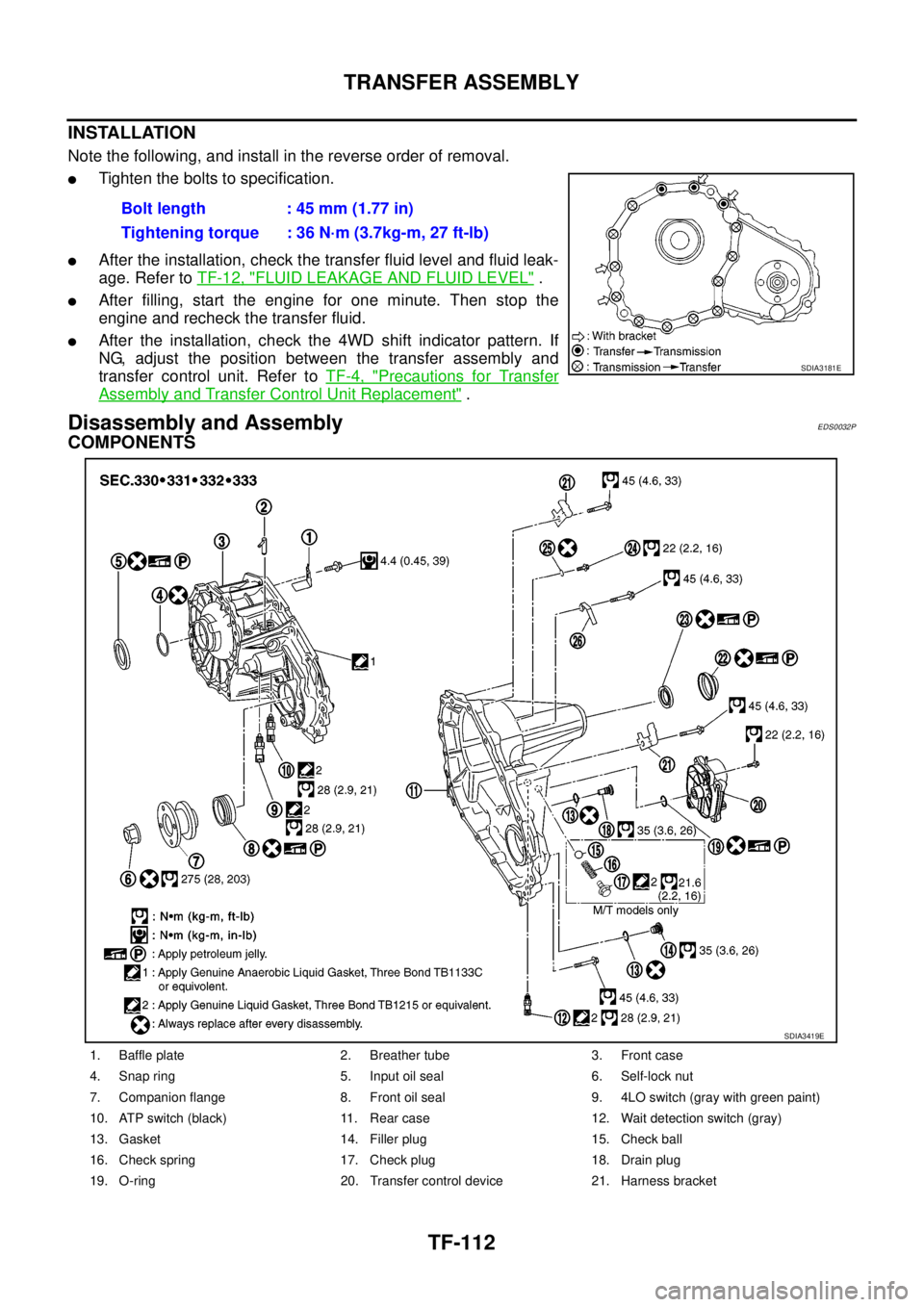
COMPONENTS
Bolt length : 45 mm (1.77 in)
Tightening torque : 36 N·m (3.7kg-m, 27 ft-lb)
SDIA3181E
1. Baffle plate 2. Breather tube 3. Front case
4. Snap ring 5. Input oil seal 6. Self-lock nut
7. Companion flange 8. Front oil seal 9. 4LO switch (gray with green paint)
10. ATP switch (black) 11. Rear case 12. Wait detection switch (gray)
13. Gasket 14. Filler plug 15. Check ball
16. Check spring 17. Check plug 18. Drain plug
19. O-ring 20. Transfer control device 21. Harness bracket
SDIA3419E
Page 3129 of 3171
WW-18
FRONT WIPER AND WASHER SYSTEM
CONSULT-II Function (BCM)
EKS00P53
CONSULT-II can display each diagnostic item using the diagnostic test modes shown following.
CONSULT-II OPERATION
CAUTION:
If CONSULT-II is used with no connection of CONSULT-II CONVERTER, malfunctions might be
detected in self-diagnosis depending on control unit which carries out CAN communication.
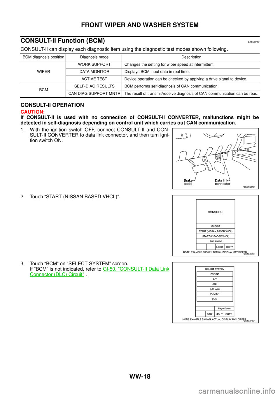
1. With the ignition switch OFF, connect CONSULT-II and CON-
SULT-II CONVERTER to data link connector, and then turn igni-
tion switch ON.
2. Touch “START (NISSAN BASED VHCL)”.
3. Touch “BCM” on “SELECT SYSTEM” screen.
If “BCM” is not indicated, refer toGI-50, "
CONSULT-II Data Link
Connector (DLC) Circuit".
BCM diagnosis position Diagnosis mode Description
WIPERWORK SUPPORT Changes the setting for wiper speed at intermittent.
DATA MONITOR Displays BCM input data in real time.
ACTIVE TEST Device operation can be checked by applying a drive signal to device.
BCMSELF-DIAG RESULTS BCM performs self-diagnosis of CAN communication.
CAN DIAG SUPPORT MNTR The result of transmit/receive diagnosis of CAN communication can be read.
BBIA0538E
BCIA0029E
BCIA0030E
Page 3130 of 3171
FRONT WIPER AND WASHER SYSTEM
WW-19
C
D
E
F
G
H
I
J
L
MA
B
WW
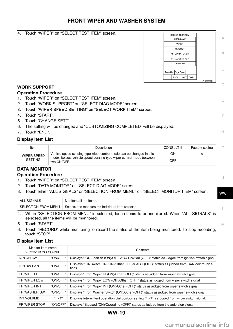
4. Touch “WIPER” on “SELECT TEST ITEM” screen.
WORK SUPPORT
Operation Procedure
1. Touch “WIPER” on “SELECT TEST ITEM” screen.
2. Touch “WORK SUPPORT” on “SELECT DIAG MODE” screen.
3. Touch “WIPER SPEED SETTING” on “SELECT WORK ITEM” screen.
4. Touch “START”.
5. Touch “CHANGE SETT”.
6. The setting will be changed and “CUSTOMIZING COMPLETED” will be displayed.
7. Touch “END”.
Display Item List
DATA MONITOR
Operation Procedure
1. Touch “WIPER” on “SELECT TEST ITEM” screen.
2. Touch “DATA MONITOR” on “SELECT DIAG MODE” screen.
3. Touch either “ALL SIGNALS” or “SELECTION FROM MENU” on “SELECT MONITOR ITEM” screen.
4. When “SELECTION FROM MENU” is selected, touch items to be monitored. When “ALL SIGNALS” is
selected, all the items will be monitored.
5. Touch “START”.
6. Touch “RECORD” while monitoring to record the status of the item being monitored. To stop recording,
touch “STOP”.
Display Item List
PKIB6096E
Item Description CONSULT-II Factory setting
WIPER SPEED
SETTINGVehicle speed sensing type wiper control mode can be changed in this
mode. Selects vehicle speed sensing type wiper control mode between
two ON/OFF.ON´
OFF —
ALL SIGNALS Monitors all the items.
SELECTION FROM MENU Selects and monitors the individual item selected.
Monitor item name
“OPERATION OR UNIT”Contents
IGN ON SW “ON/OFF” Displays “IGN Position (ON)/OFF, ACC Position (OFF)” status as judged from ignition switch signal.
IGN SW CAN “ON/OFF”Displays “IGN switch ON (ON)/Other OFF or ACC (OFF)” status as judged from CAN communica-
tions.
FR WIPER HI “ON/OFF” Displays “Front Wiper HI (ON)/Other (OFF)” status as judged from wiper switch signal.
FR WIPER LOW “ON/OFF” Displays “Front Wiper LOW (ON)/Other (OFF)” status as judged from wiper switch signal.
FR WIPER INT “ON/OFF” Displays “Front Wiper INT (ON)/Other (OFF)” status as judged from wiper switch signal.
FR WASHER SW “ON/OFF” Displays “Front Washer Switch (ON)/Other (OFF)” status as judged from wiper switch signal.
INT VOLUME “1 - 7” Displays intermittent operation dial position setting (1 - 7) as judged from wiper switch signal.
FR WIPER STOP “ON/OFF” Displays “Stopped (ON)/Operating (OFF)” status as judged from the auto stop signal.
Page 3132 of 3171
FRONT WIPER AND WASHER SYSTEM
WW-21
C
D
E
F
G
H
I
J
L
MA
B
WW
CONSULT-II Function (IPDM E/R)EKS00P54
CONSULT-II can display each diagnostic item using the diagnostic test modes shown following.
CONSULT-II OPERATION
CAUTION:
If CONSULT-II is used with no connection of CONSULT-II CONVERTER, malfunctions might be
detected in self-diagnosis depending on control unit which carries out CAN communication.
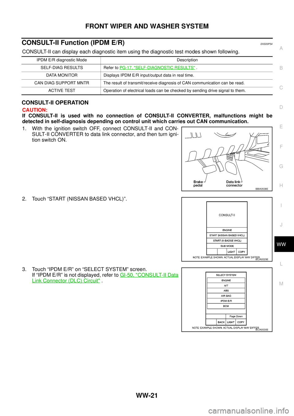
1. With the ignition switch OFF, connect CONSULT-II and CON-
SULT-II CONVERTER to data link connector, and then turn igni-
tion switch ON.
2. Touch “START (NISSAN BASED VHCL)”.
3. Touch “IPDM E/R” on “SELECT SYSTEM” screen.
If “IPDM E/R” is not displayed, refer toGI-50, "
CONSULT-II Data
Link Connector (DLC) Circuit".
IPDM E/R diagnostic Mode Description
SELF-DIAG RESULTS Refer toPG-17, "
SELF-DIAGNOSTIC RESULTS".
DATA MONITOR Displays IPDM E/R input/output data in real time.
CAN DIAG SUPPORT MNTR The result of transmit/receive diagnosis of CAN communication can be read.
ACTIVE TEST Operation of electrical loads can be checked by sending drive signal to them.
BBIA0538E
BCIA0029E
BCIA0030E
Page 3133 of 3171
WW-22
FRONT WIPER AND WASHER SYSTEM
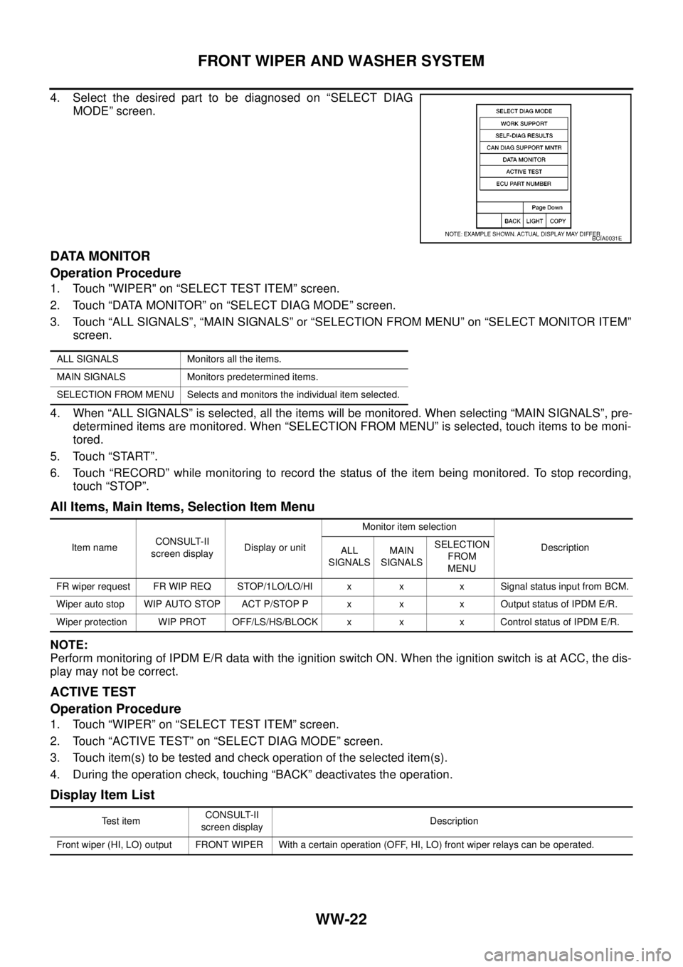
4. Select the desired part to be diagnosed on “SELECT DIAG
MODE” screen.
DATA MONITOR
Operation Procedure
1. Touch "WIPER" on “SELECT TEST ITEM” screen.
2. Touch “DATA MONITOR” on “SELECT DIAG MODE” screen.
3. Touch “ALL SIGNALS”, “MAIN SIGNALS” or “SELECTION FROM MENU” on “SELECT MONITOR ITEM”
screen.
4. When “ALL SIGNALS” is selected, all the items will be monitored. When selecting “MAIN SIGNALS”, pre-
determined items are monitored. When “SELECTION FROM MENU” is selected, touch items to be moni-
tored.
5. Touch “START”.
6. Touch “RECORD” while monitoring to record the status of the item being monitored. To stop recording,
touch “STOP”.
All Items, Main Items, Selection Item Menu
NOTE:
Perform monitoring of IPDM E/R data with the ignition switch ON. When the ignition switch is at ACC, the dis-
play may not be correct.
ACTIVE TEST
Operation Procedure
1. Touch “WIPER” on “SELECT TEST ITEM” screen.
2. Touch “ACTIVE TEST” on “SELECT DIAG MODE” screen.
3. Touch item(s) to be tested and check operation of the selected item(s).
4. During the operation check, touching “BACK” deactivates the operation.
Display Item List
BCIA0031E
ALL SIGNALS Monitors all the items.
MAIN SIGNALS Monitors predetermined items.
SELECTION FROM MENU Selects and monitors the individual item selected.
Item nameCONSULT-II
screen displayDisplay or unitMonitor item selection
Description
ALL
SIGNALSMAIN
SIGNALSSELECTION
FROM
MENU
FR wiper request FR WIP REQ STOP/1LO/LO/HI x x x Signal status input from BCM.
Wiper auto stop WIP AUTO STOP ACT P/STOP P x x x Output status of IPDM E/R.
Wiper protection WIP PROT OFF/LS/HS/BLOCK x x x Control status of IPDM E/R.
Te s t i t e mCONSULT-II
screen displayDescription
Front wiper (HI, LO) output FRONT WIPER With a certain operation (OFF, HI, LO) front wiper relays can be operated.
Page 3150 of 3171
HEADLAMP WASHER
WW-39
C
D
E
F
G
H
I
J
L
MA
B
WW
HEADLAMP WASHERPFP:28620
Components Parts and Harness Connector LocationEKS00P67
System DescriptionEKS00P68
Headlamp washer operates under the following conditions.
lWhen lighting switch is in 1ST position
lWhen daytime light system is operating
lWhen auto light system is operating (LOW beam is ON)
When the headlamp washer switch is ON position the BCM (body control module) receives input signal
requesting the headlamp washer operates. The CPU (central processing unit) of the IPDM E/R (intelligent
power distribution module engine room) controls the headlamp washer relay coil. When activated this relay
directs power headlamp washer motor.
SKIB6860E