2005 NISSAN NAVARA parking brake
[x] Cancel search: parking brakePage 2281 of 3171

MA-6
DESCRIPTION
ROAD TEST
Check clutch operation
Check foot brake operation
Check parking brake operation
Check steering operation, self-centering and steering wheel alignment
Check engine performance
Check for squeaks, rattles and noise from interior, suspension and brakes
Check heating, ventilation and air conditioning operation
Check radio, cassette and CD player operation
Check odometer and trip meter operation and cancelling
Check instruments for operation
Check automatic transmission/transaxle shift pattern and kickdown operation (if applicable)
Check cruise control and navigation system operation (if applicable)
ENGINE OPERATING AND HOT
Check idle speed
Check automatic transmission/transaxle oil level (if applicable)
FINAL INSPECTION
Remove vehicle protection kit
Fit interior mats and wheel covers
Check for interior and exterior metal and paint damage
Wash, clean interior and exterior
: Not applicable to this model
Page 2282 of 3171
GENERAL MAINTENANCE
MA-7
C
D
E
F
G
H
I
J
K
MA
B
MA
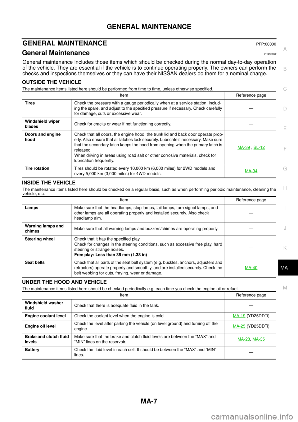
GENERAL MAINTENANCEPFP:00000
General MaintenanceELS001HT
General maintenance includes those items which should be checked during the normal day-to-day operation
of the vehicle. They are essential if the vehicle is to continue operating properly. The owners can perform the
checks and inspections themselves or they can have their NISSAN dealers do them for a nominal charge.
OUTSIDE THE VEHICLE
The maintenance items listed here should be performed from time to time, unless otherwise specified.
INSIDE THE VEHICLE
The maintenance items listed here should be checked on a regular basis, such as when performing periodic maintenance, cleaning the
vehicle, etc.
UNDER THE HOOD AND VEHICLE
The maintenance items listed here should be checked periodically e.g. each time you check the engine oil or refuel.Item Reference page
TiresCheck the pressure with a gauge periodically when at a service station, includ-
ing the spare, and adjust to the specified pressure if necessary. Check carefully
for damage, cuts or excessive wear.—
Windshield wiper
bladesCheck for cracks or wear if not functioning correctly. —
Doors and engine
hoodCheck that all doors, the engine hood, the trunk lid and back door operate prop-
erly. Also ensure that all latches lock securely. Lubricate if necessary. Make sure
that the secondary latch keeps the hood from opening when the primary latch is
released.
When driving in areas using road salt or other corrosive materials, check for
lubrication frequently.MA-39
,BL-12
Tire rotationTires should be rotated every 10,000 km (6,000 miles) for 2WD models and
every 5,000 km (3,000 miles) for 4WD models.MA-34
Item Reference page
LampsMake sure that the headlamps, stop lamps, tail lamps, turn signal lamps, and
other lamps are all operating properly and installed securely. Also check
headlamp aim.—
Warning lamps and
chimesMake sure that all warning lamps and buzzers/chimes are operating properly. —
Steering wheelCheck that it has the specified play.
Check for changes in the steering conditions, such as excessive free play, hard
steering or strange noises.
Free play: Less than 35 mm (1.38 in)—
Seat beltsCheck that all parts of the seat belt system (e.g. buckles, anchors, adjusters and
retractors) operate properly and smoothly, and are installed securely. Check the
belt webbing for cuts, fraying, wear or damage.MA-40
Item Reference page
Windshield washer
fluidCheck that there is adequate fluid in the tank. —
Engine coolant levelCheck the coolant level when the engine is cold.MA-19
(YD25DDTi)
Engine oil levelCheck the level after parking the vehicle (on level ground) and turning off the
engine.MA-25
(YD25DDTi)
Brake and clutch fluid
levelsMake sure that the brake and clutch fluid levels are between the “MAX” and
“MIN” lines on the reservoir.MA-28
,MA-35
BatteryCheck the fluid level in each cell. It should be between the “MAX” and “MIN”
lines.—
Page 2284 of 3171
PERIODIC MAINTENANCE
MA-9
C
D
E
F
G
H
I
J
K
MA
B
MA
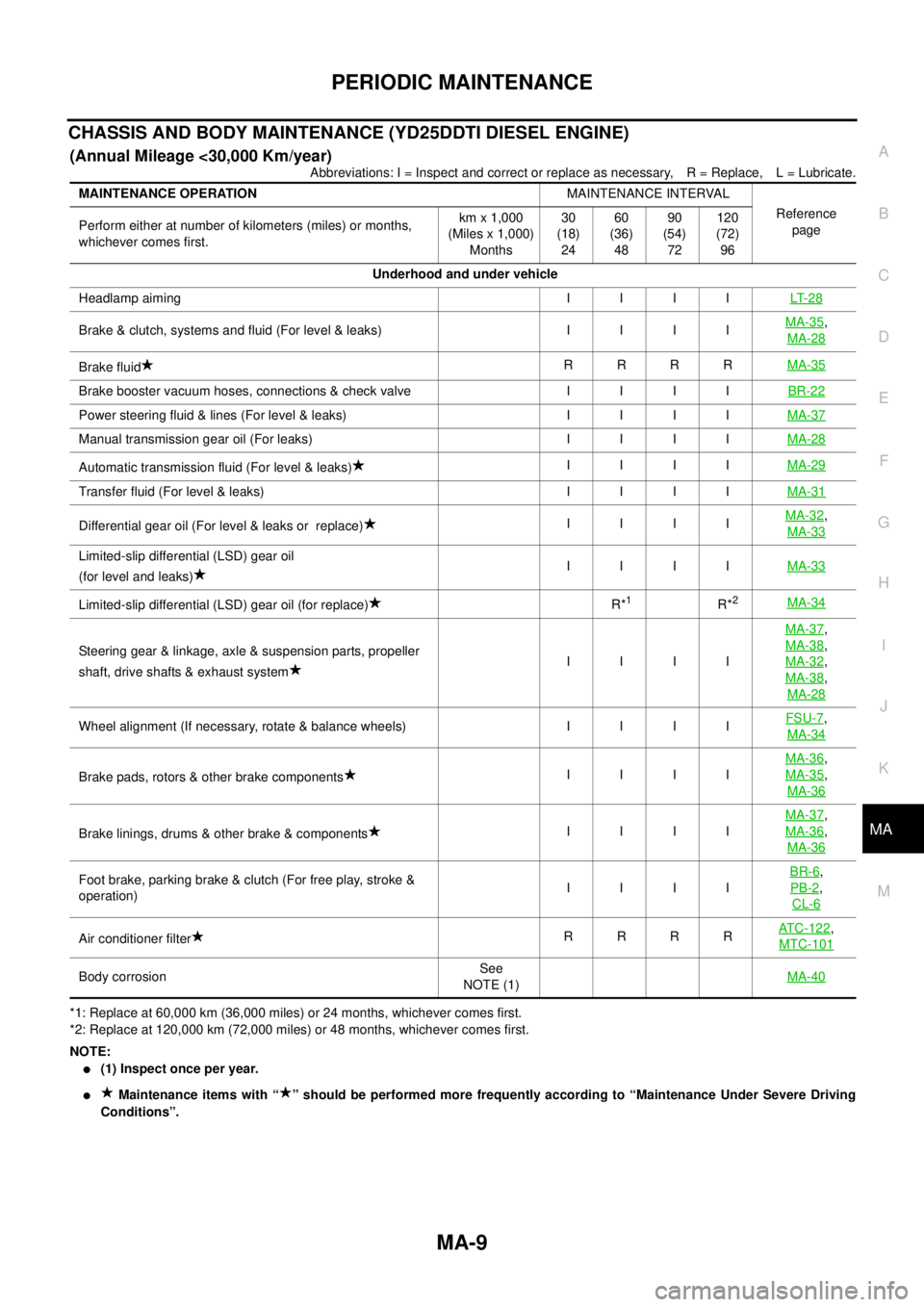
CHASSIS AND BODY MAINTENANCE (YD25DDTI DIESEL ENGINE)
(Annual Mileage <30,000 Km/year)
Abbreviations: I = Inspect and correct or replace as necessary, R = Replace, L = Lubricate.
*1: Replace at 60,000 km (36,000 miles) or 24 months, whichever comes first.
*2: Replace at 120,000 km (72,000 miles) or 48 months, whichever comes first.
NOTE:
l(1) Inspect once per year.
lMaintenance items with “ ” should be performed more frequently according to “Maintenance Under Severe Driving
Conditions”. MAINTENANCE OPERATIONMAINTENANCE INTERVAL
Reference
page Perform either at number of kilometers (miles) or months,
whichever comes first.km x 1,000
(Miles x 1,000)
Months30
(18)
2460
(36)
4890
(54)
72120
(72)
96
Underhood and under vehicle
Headlampaiming IIIILT- 2 8
Brake&clutch,systemsandfluid(Forlevel&leaks) IIIIMA-35,
MA-28
Brake fluidRRRRMA-35
Brakeboostervacuumhoses,connections&checkvalve IIIIBR-22
Powersteeringfluid&lines(Forlevel&leaks) IIIIMA-37
Manual transmission gear oil (For leaks)IIIIMA-28
Automatic transmission fluid (For level & leaks)IIIIMA-29
Transferfluid(Forlevel&leaks) IIIIMA-31
Differential gear oil (For level & leaks or replace)IIIIMA-32,
MA-33
Limited-slip differential (LSD) gear oil
(for level and leaks)IIIIMA-33
Limited-slip differential (LSD) gear oil (for replace)R*1R*2MA-34
Steering gear & linkage, axle & suspension parts, propeller
shaft, drive shafts & exhaust systemIIIIMA-37
,
MA-38
,
MA-32
,
MA-38
,
MA-28
Wheelalignment(Ifnecessary,rotate&balancewheels) IIIIFSU-7,
MA-34
Brake pads, rotors & other brake componentsIIIIMA-36
,
MA-35
,
MA-36
Brake linings, drums & other brake & componentsIIIIMA-37
,
MA-36
,
MA-36
Foot brake, parking brake & clutch (For free play, stroke &
operation)IIIIBR-6,
PB-2
,
CL-6
Air conditioner filterRRRRATC-122,
MTC-101
Body corrosionSee
NOTE (1)MA-40
Page 2287 of 3171
MA-12
PERIODIC MAINTENANCE
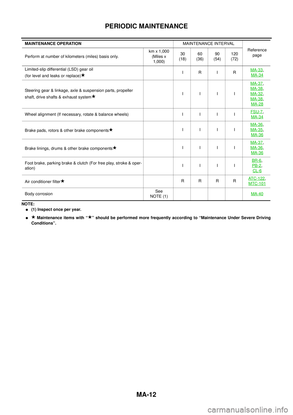
NOTE:
l(1) Inspect once per year.
lMaintenance items with “ ” should be performed more frequently according to “Maintenance Under Severe Driving
Conditions”. Limited-slip differential (LSD) gear oil
(for level and leaks or replace)IRIRMA-33
,
MA-34
Steering gear & linkage, axle & suspension parts, propeller
shaft, drive shafts & exhaust systemIIIIMA-37
,
MA-38
,
MA-32
,
MA-38
,
MA-28
Wheel alignment (If necessary, rotate & balance wheels) I I I IFSU-7,
MA-34
Brake pads, rotors & other brake componentsIIIIMA-36
,
MA-35
,
MA-36
Brake linings, drums & other brake componentsIIIIMA-37
,
MA-36
,
MA-36
Foot brake, parking brake & clutch (For free play, stroke & oper-
ation)IIIIBR-6,
PB-2
,
CL-6
Air conditioner filterRRRRAT C - 1 2 2,
MTC-101
Body corrosionSee
NOTE (1)MA-40
MAINTENANCE OPERATIONMAINTENANCE INTERVAL
Reference
page
Perform at number of kilometers (miles) basis only.km x 1,000
(Miles x
1,000)30
(18)60
(36)90
(54)120
(72)
Page 2304 of 3171
CHASSIS AND BODY MAINTENANCE
MA-29
C
D
E
F
G
H
I
J
K
MA
B
MA
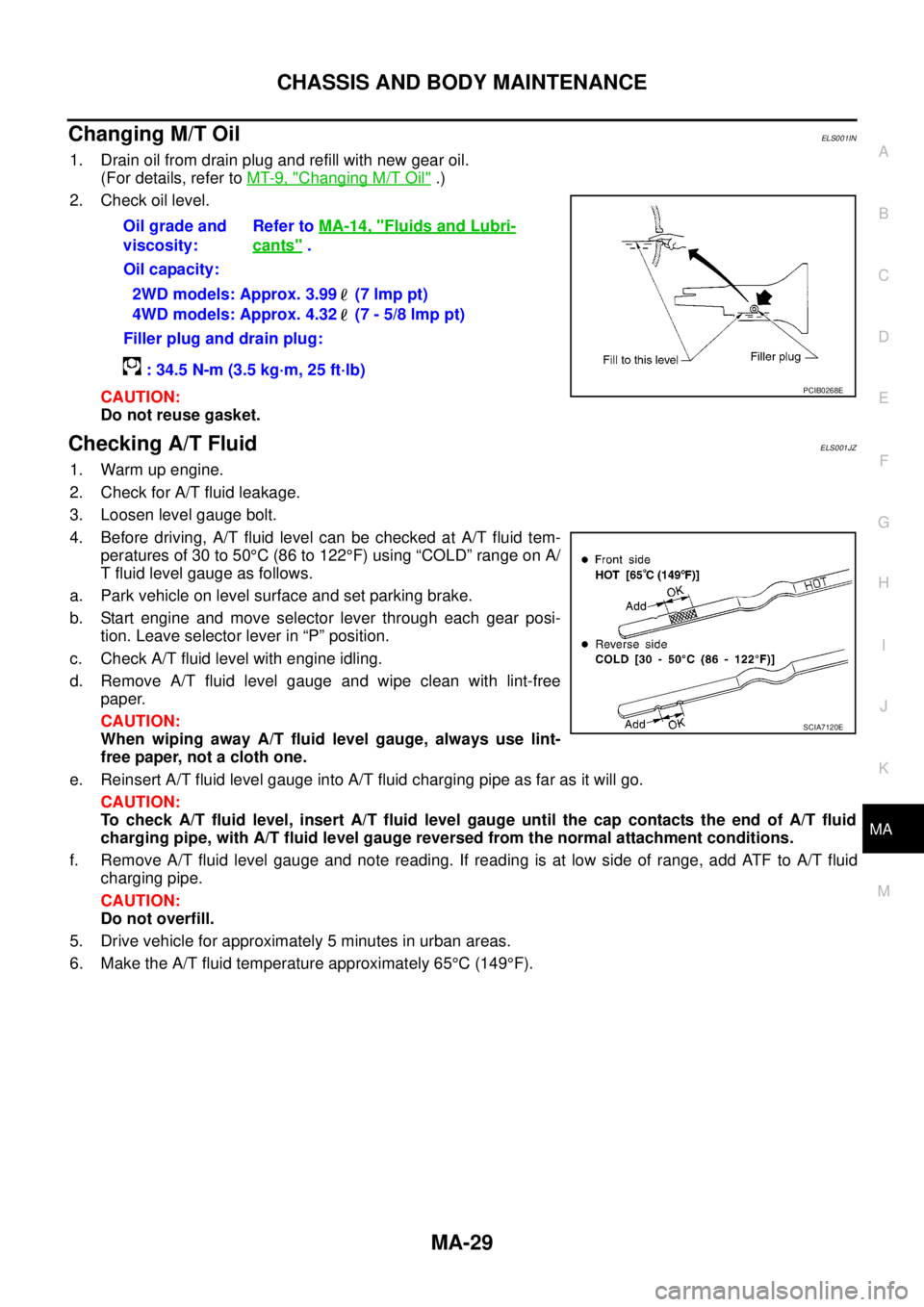
Changing M/T OilELS001IN
1. Drain oil from drain plug and refill with new gear oil.
(For details, refer toMT-9, "
Changing M/T Oil".)
2. Check oil level.
CAUTION:
Do not reuse gasket.
Checking A/T FluidELS001JZ
1. Warm up engine.
2. Check for A/T fluid leakage.
3. Loosen level gauge bolt.
4. Before driving, A/T fluid level can be checked at A/T fluid tem-
peraturesof30to50°C(86to122°F) using “COLD” range on A/
T fluid level gauge as follows.
a. Park vehicle on level surface and set parking brake.
b. Start engine and move selector lever through each gear posi-
tion. Leave selector lever in “P” position.
c. Check A/T fluid level with engine idling.
d. Remove A/T fluid level gauge and wipe clean with lint-free
paper.
CAUTION:
When wiping away A/T fluid level gauge, always use lint-
free paper, not a cloth one.
e. Reinsert A/T fluid level gauge into A/T fluid charging pipe as far as it will go.
CAUTION:
To check A/T fluid level, insert A/T fluid level gauge until the cap contacts the end of A/T fluid
charging pipe, with A/T fluid level gauge reversed from the normal attachment conditions.
f. Remove A/T fluid level gauge and note reading. If reading is at low side of range, add ATF to A/T fluid
charging pipe.
CAUTION:
Do not overfill.
5. Drive vehicle for approximately 5 minutes in urban areas.
6. Make the A/T fluid temperature approximately 65°C(149°F). Oil grade and
viscosity:Refer toMA-14, "
Fluids and Lubri-
cants".
Oil capacity:
2WD models: Approx. 3.99 (7 lmp pt)
4WD models: Approx. 4.32 (7 - 5/8 lmp pt)
Filler plug and drain plug:
: 34.5 N-m (3.5 kg·m, 25 ft·lb)
PCIB0268E
SCIA7120E
Page 2310 of 3171
CHASSIS AND BODY MAINTENANCE
MA-35
C
D
E
F
G
H
I
J
K
MA
B
MA
Checking Brake Fluid Level and LeaksELS001IZ
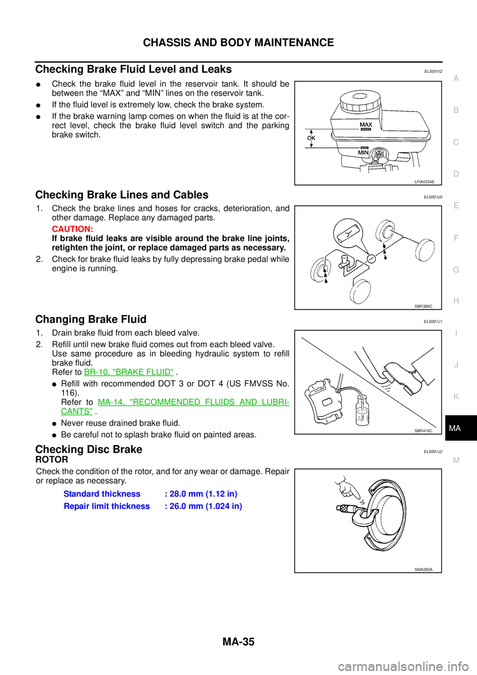
lCheck the brake fluid level in the reservoir tank. It should be
between the “MAX” and “MIN” lines on the reservoir tank.
lIf the fluid level is extremely low, check the brake system.
lIf the brake warning lamp comes on when the fluid is at the cor-
rect level, check the brake fluid level switch and the parking
brake switch.
Checking Brake Lines and CablesELS001J0
1. Check the brake lines and hoses for cracks, deterioration, and
other damage. Replace any damaged parts.
CAUTION:
If brake fluid leaks are visible around the brake line joints,
retighten the joint, or replace damaged parts as necessary.
2. Check for brake fluid leaks by fully depressing brake pedal while
engine is running.
Changing Brake FluidELS001J1
1. Drain brake fluid from each bleed valve.
2. Refill until new brake fluid comes out from each bleed valve.
Use same procedure as in bleeding hydraulic system to refill
brake fluid.
Refer toBR-10, "
BRAKE FLUID".
lRefill with recommended DOT 3 or DOT 4 (US FMVSS No.
11 6 ) .
Refer toMA-14, "
RECOMMENDED FLUIDS AND LUBRI-
CANTS".
lNever reuse drained brake fluid.
lBe careful not to splash brake fluid on painted areas.
Checking Disc BrakeELS001J2
ROTOR
Check the condition of the rotor, and for any wear or damage. Repair
or replace as necessary.
LFIA0234E
SBR389C
SBR419C
Standard thickness : 28.0 mm (1.12 in)
Repair limit thickness : 26.0 mm (1.024 in)
SMA260A
Page 2524 of 3171

PB-1
PARKING BRAKE SYSTEM
F BRAKES
CONTENTS
C
D
E
G
H
I
J
K
L
M
SECTIONPB
A
B
PB
PARKING BRAKE SYSTEM
PARKING BRAKE CONTROL ................................... 2
On-Vehicle Service ................................................... 2
INSPECTION ........................................................ 2
COMPONENTS INSPECTION ............................. 2
ADJUSTMENT ...................................................... 2Components ............................................................. 3
Removal and Installation .......................................... 4
REMOVAL ............................................................. 4
INSTALLATION ..................................................... 5
SERVICE DATA AND SPECIFICATIONS (SDS) ........ 6
Parking Brake Control .............................................. 6
Page 2525 of 3171
PB-2
PARKING BRAKE CONTROL
PARKING BRAKE CONTROL
PFP:36010
On-Vehicle ServiceEFS006AJ
INSPECTION
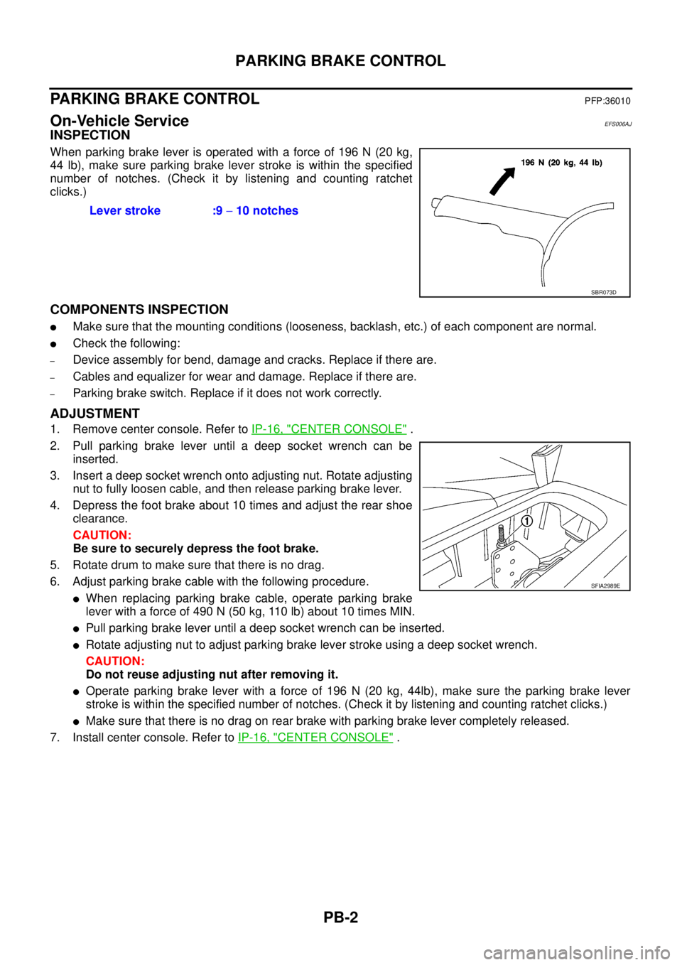
When parking brake lever is operated with a force of 196 N (20 kg,
44 lb), make sure parking brake lever stroke is within the specified
number of notches. (Check it by listening and counting ratchet
clicks.)
COMPONENTS INSPECTION
lMake sure that the mounting conditions (looseness, backlash, etc.) of each component are normal.
lCheck the following:
–Device assembly for bend, damage and cracks. Replace if there are.
–Cables and equalizer for wear and damage. Replace if there are.
–Parking brake switch. Replace if it does not work correctly.
ADJUSTMENT
1. Remove center console. Refer toIP-16, "CENTER CONSOLE".
2. Pull parking brake lever until a deep socket wrench can be
inserted.
3. Insert a deep socket wrench onto adjusting nut. Rotate adjusting
nut to fully loosen cable, and then release parking brake lever.
4. Depress the foot brake about 10 times and adjust the rear shoe
clearance.
CAUTION:
Be sure to securely depress the foot brake.
5. Rotate drum to make sure that there is no drag.
6. Adjust parking brake cable with the following procedure.
lWhen replacing parking brake cable, operate parking brake
leverwithaforceof490N(50kg,110lb)about10timesMIN.
lPull parking brake lever until a deep socket wrench can be inserted.
lRotate adjusting nut to adjust parking brake lever stroke using a deep socket wrench.
CAUTION:
Do not reuse adjusting nut after removing it.
lOperate parking brake lever with a force of 196 N (20 kg, 44lb), make sure the parking brake lever
stroke is within the specified number of notches. (Check it by listening and counting ratchet clicks.)
lMake sure that there is no drag on rear brake with parking brake lever completely released.
7. Install center console. Refer toIP-16, "
CENTER CONSOLE". Lever stroke :9-10 notches
SBR073D
SFIA2989E