2005 NISSAN NAVARA parking brake
[x] Cancel search: parking brakePage 819 of 3171
REAR DRUM BRAKE
BR-33
C
D
E
G
H
I
J
K
L
MA
B
BR
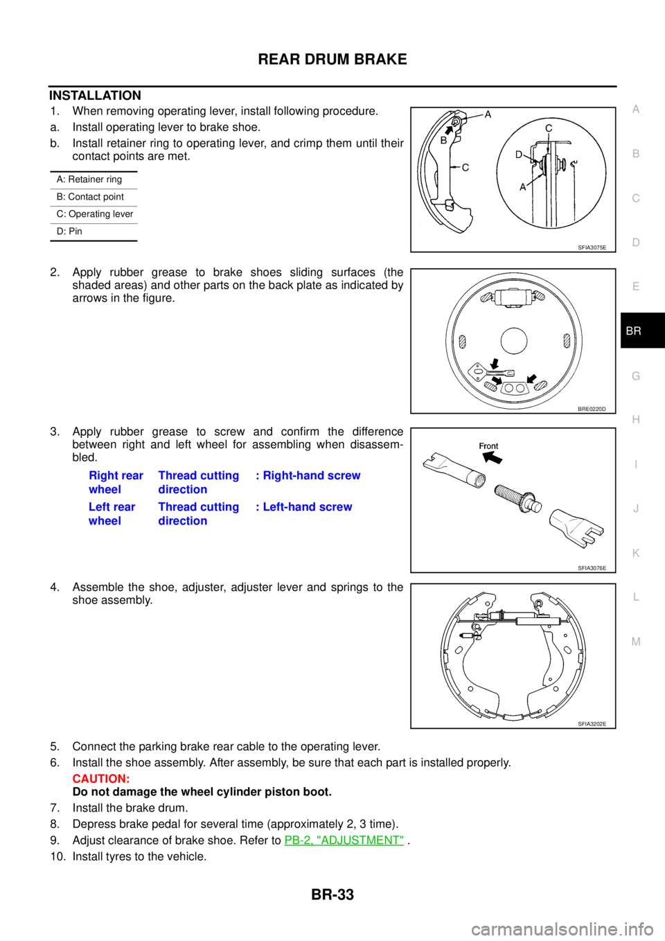
INSTALLATION
1. When removing operating lever, install following procedure.
a. Install operating lever to brake shoe.
b. Install retainer ring to operating lever, and crimp them until their
contact points are met.
2. Apply rubber grease to brake shoes sliding surfaces (the
shaded areas) and other parts on the back plate as indicated by
arrows in the figure.
3. Apply rubber grease to screw and confirm the difference
between right and left wheel for assembling when disassem-
bled.
4. Assemble the shoe, adjuster, adjuster lever and springs to the
shoe assembly.
5. Connect the parking brake rear cable to the operating lever.
6. Install the shoe assembly. After assembly, be sure that each part is installed properly.
CAUTION:
Do not damage the wheel cylinder piston boot.
7. Install the brake drum.
8. Depress brake pedal for several time (approximately 2, 3 time).
9. Adjust clearance of brake shoe. Refer toPB-2, "
ADJUSTMENT".
10. Install tyres to the vehicle.
A: Retainer ring
B: Contact point
C: Operating lever
D: Pin
SFIA3075E
BRE0220D
Right rear
wheelThread cutting
direction: Right-hand screw
Left rear
wheelThread cutting
direction: Left-hand screw
SFIA3076E
SFIA3202E
Page 823 of 3171
BRC-1
BRAKE CONTROL SYSTEM
F BRAKES
CONTENTS
C
D
E
G
H
I
J
K
L
M
SECTIONBRC
A
B
BRC
BRAKE CONTROL SYSTEM
ABS
PRECAUTIONS .......................................................... 3
Precautions for Supplemental Restraint System
(SRS)“AIRBAG”and“SEATBELTPRE-TEN-
SIONER” .................................................................. 3
Precautions for Brake System .................................. 3
Precautions for Brake Control .................................. 3
PREPARATION ........................................................... 4
Special Service Tools (SST) ..................................... 4
SYSTEM DESCRIPTION ............................................ 5
System Diagram ....................................................... 5
Functions .................................................................. 5
Operation That Is Not “System Error” ...................... 5
Fail-Safe Function .................................................... 5
ABS, EBD SYSTEM .............................................. 5
Hydraulic Circuit Diagram ........................................ 6
CAN COMMUNICATION ............................................ 7
System Description .................................................. 7
TROUBLE DIAGNOSIS .............................................. 8
How to Perform Trouble Diagnosis for Quick and
Accurate Repair ....................................................... 8
INTRODUCTION ................................................... 8
DIAGNOSIS FLOWCHART .................................. 9
ASKING COMPLAINTS ...................................... 10
EXAMPLE OF DIAGNOSIS SHEET ................... 10
Component Parts Location ...................................... 11
Schematic — ABS — ............................................. 12
Wiring Diagram — ABS — ..................................... 13
CONSULT- II Functions .......................................... 17
CONSULT-II MAIN FUNCTION ........................... 17
CONSULT-II BASIC OPERATION PROCEDURE
... 17
Self-Diagnosis ........................................................ 18
OPERATION PROCEDURE ............................... 18
ERASE MEMORY ............................................... 18
DISPLAY ITEM LIST ........................................... 18
Data Monitor ........................................................... 20
OPERATION PROCEDURE ............................... 20
DISPLAY ITEM LIST ........................................... 20Active Test .............................................................. 21
OPERATION PROCEDURE ................................ 21
SOLENOID VALVE .............................................. 22
ABS MOTOR ....................................................... 22
For Fast and Accurate Diagnosis ........................... 23
PRECAUTIONS FOR DIAGNOSIS ..................... 23
Basic Inspection ..................................................... 23
BASIC INSPECTION 1 BRAKE FLUID LEVEL,
LEAKS, AND BRAKE PADS ................................ 23
BASIC INSPECTION 2 POWER SYSTEM TER-
MINAL LOOSENESS AND BATTERY INSPEC-
TION .................................................................... 23
BASIC INSPECTION 3 ABS WARNING LAMP
AND BRAKE WARNING LAMP INSPECTION .... 24
Inspection 1 Wheel Sensor System ........................ 24
Inspection 2 ABS Actuator and Electric Unit (Control
Unit) ........................................................................ 26
Inspection 3 ABS Actuator Relay or ABS Motor
Relay Circuit ........................................................... 26
Inspection 4 CAN Communication Circuit .............. 28
Inspection 5 ABS Actuator and Electric Unit (Control
Unit) Power Supply and Ground Circuit .................. 28
Inspection 6 Brake Fluid Level Switch Circuit ......... 30
Inspection 7 Parking Brake Switch Circuit .............. 32
Inspection 8 Warning lamp system ......................... 33
Symptom 1: Excessive ABS Function Operation
Frequency ............................................................... 33
Symptom 2: Unexpected Pedal Reaction ............... 34
Symptom 3: The Stopping Distance Is Long .......... 34
Symptom 4: ABS Function Does Not Operate ....... 35
Symptom 5: Pedal Vibration or ABS Operation
Sound Occurs ......................................................... 35
Symptom 6: ABS Warning Lamp Indication Is Not
Normal .................................................................... 35
WHEEL SENSORS ................................................... 37
Removal and Installation ........................................ 37
REMOVAL ........................................................... 38
INSTALLATION ................................................... 38
Page 846 of 3171
![NISSAN NAVARA 2005 Repair Workshop Manual BRC-24
[ABS]
TROUBLE DIAGNOSIS
BASIC INSPECTION 3 ABS WARNING LAMP AND BRAKE WARNING LAMP INSPECTION
ON and OFF Timing for ABS Warning Lamp, Brake Warning Lamp
´:ON –:OFF
Note 1:Brake warning lamp NISSAN NAVARA 2005 Repair Workshop Manual BRC-24
[ABS]
TROUBLE DIAGNOSIS
BASIC INSPECTION 3 ABS WARNING LAMP AND BRAKE WARNING LAMP INSPECTION
ON and OFF Timing for ABS Warning Lamp, Brake Warning Lamp
´:ON –:OFF
Note 1:Brake warning lamp](/manual-img/5/57362/w960_57362-845.png)
BRC-24
[ABS]
TROUBLE DIAGNOSIS
BASIC INSPECTION 3 ABS WARNING LAMP AND BRAKE WARNING LAMP INSPECTION
ON and OFF Timing for ABS Warning Lamp, Brake Warning Lamp
´:ON –:OFF
Note 1:Brake warning lamp will turn on in case of operating parking brake (switch turned on) or of a actuating brake fluid level switch
(brake fluid is insufficient).
Note 2:After starting engine, turn OFF.
Check the following items when unsuitable for an above condition.
lABS warning lamp: Refer toBRC-28, "Inspection 4 CAN Communication Circuit".
lBrake waning lamp: Refer toBRC-28, "Inspection 4 CAN Communication Circuit",BRC-30, "Inspection 6
Brake Fluid Level Switch Circuit",BRC-32, "Inspection 7 Parking Brake Switch Circuit".
If malfunction is not found, refer toBRC-33, "
Inspection 8 Warning lamp system".
Inspection 1 Wheel Sensor SystemEFS005TZ
Check each part according to CONSULT-II self-diagnostic results, and then identify the parts to be replaced.
CAUTION:
Check each part between wheel sensor terminals.
INSPECTION PROCEDURE
1.CHECK SELF-DIAGNOSTIC RESULTS
Check self-diagnostic results.
Is above displayed in self-diagnosis display items?
YES >> GO TO 2.
NO >> INSPECTION END
2.CHECK TYRE
Check air pressure, wear and size.
Are air pressure, wear and size within standard values?
YES >> GO TO 3.
NO >> Adjust air pressure, or replace tyre.
Condition ABS warning lampBrake warning lamp
[Note 1]Remarks
Ignition SW OFF – — —
Approx. 2 seconds after ignition
switch is turned ON´´[Note 2] —
Approx. 2 seconds later after ignition
switch ON–´[Note 2]Go out 2 seconds after ignition
switch is turned ON.
ABS error´—There is an ABS actuator and
electric unit (control unit) error.
(Power, ground or system mal-
function)
EBD error´´—
Self-diagnostic results
FR RH SENSOR-1,-2
FR LH SENSOR- 1,-2
RR RH SENSOR-1,-2
RR LH SENSOR-1,- 2
ABS SENSOR [MALFUNCTION SIGNAL]
Page 854 of 3171
![NISSAN NAVARA 2005 Repair Workshop Manual BRC-32
[ABS]
TROUBLE DIAGNOSIS
Inspection 7 Parking Brake Switch Circuit
EFS005U6
INSPECTION PROCEDURE
1.CHECK PARKING BRAKE SWITCH
1. Turn ignition switch OFF and disconnect parking brake switch
conn NISSAN NAVARA 2005 Repair Workshop Manual BRC-32
[ABS]
TROUBLE DIAGNOSIS
Inspection 7 Parking Brake Switch Circuit
EFS005U6
INSPECTION PROCEDURE
1.CHECK PARKING BRAKE SWITCH
1. Turn ignition switch OFF and disconnect parking brake switch
conn](/manual-img/5/57362/w960_57362-853.png)
BRC-32
[ABS]
TROUBLE DIAGNOSIS
Inspection 7 Parking Brake Switch Circuit
EFS005U6
INSPECTION PROCEDURE
1.CHECK PARKING BRAKE SWITCH
1. Turn ignition switch OFF and disconnect parking brake switch
connector (LHD model: B12, RHD model: B109). For brake fluid
level switch, refer toDI-10, "
Wiring Diagram—METER—".
2. Check continuity between parking brake switch connector and
ground.
OK or NG
OK >> GO TO 2.
NG >> Replace parking brake switch.
2.CHECK HARNESS
1. Disconnect combination meter connector M23.
2. Check continuity between parking brake switch connector (LHD
model: B12, RHD model: B109), combination meter connector
M23 and ground.
OK or NG
OK >> INSPECTION END
NG >> If the open or short in harness, repair or replace harness.
SFIA2935E
Measurement condition Continuity
When the parking brake pedal is operated. Yes
When the parking brake pedal is not operated. No
SFIA3055E
Parking brake switch
(harness connector B12, B109)Combination meter
(harness connector M23)Continuity
131Yes
1 Ground No
Page 928 of 3171

DI-18
COMBINATION METERS
NOTE:
Some items are not available according to vehicle specification.
*: Monitor indicating “OFF” when brake warning lamp is on because of parking brake operation or low brake
fluid level continues.
Trouble DiagnosisEKS00L8M
HOW TO PERFORM TROUBLE DIAGNOSIS
1. Confirm the symptom or customer complaint.
2. Perform preliminary check. Refer toDI-19, "
PRELIMINARY CHECK".
3. According to the symptom chart, make sure of the symptom cause and repair or replace applicable parts.
Refer toDI-19, "
Symptom Chart".
4. Does the meter operate normally? If so, GO TO 5. If not, GO TO 2.
5. INSPECTION END
KEY G W/L [ON/OFF] X Indicates [ON/OFF] condition of KEY warning lamp (green).
KEY R W/L [ON/OFF] X Indicates [ON/OFF] condition of KEY warning lamp (red).
KEY KNOB W/L [ON/OFF] X Indicates [ON/OFF] condition of LOCK warning lamp.
M RANGE SW [ON/OFF] X X Indicates [ON/OFF] condition of manual mode range switch.
NM RANGE SW [ON/OFF] X XIndicates [ON/OFF] condition of except for manual mode range
switch.
AT SFT UP SW [ON/OFF] X X Indicates [ON/OFF] condition of A/T shift-up switch.
AT SFT DWN SW [ON/OFF] X X Indicates [ON/OFF] condition of A/T shift-down switch.
O/D OFF SW [ON/OFF] X Indicates [ON/OFF] condition of OD OFF switch.
BRAKE SW [ON/OFF] X Indicates [ON/OFF] condition of parking brake switch.
AT-M IND [ON/OFF] X X Indicates [ON/OFF] condition of A/T manual mode indicator.
AT-MGEAR[1,2,3,4,5] X XIndicates [1, 2, 3, 4, 5] condition of A/T manual mode gear
position.
P RANGE IND [ON/OFF] X X Indicates [ON/OFF] condition of A/T shift P range indicator.
R RANGE IND [ON/OFF] X X Indicates [ON/OFF] condition of A/T shift R range indicator.
N RANGE IND [ON/OFF] X X Indicates [ON/OFF] condition of A/T shift N range indicator.
D RANGE IND [ON/OFF] X X Indicates [ON/OFF] condition of A/T shift D range indicator.
4 RANGE IND [ON/OFF] X X Indicates [ON/OFF] condition of A/T shift 4 range indicator.
3 RANGE IND [ON/OFF] X X Indicates [ON/OFF] condition of A/T shift 3 range indicator.
2 RANGE IND [ON/OFF] X X Indicates [ON/OFF] condition of A/T shift 2 range indicator.
1 RANGE IND [ON/OFF] X X Indicates [ON/OFF] condition of A/T shift 1range indicator.
O/D OFF W/L [ON/OFF] X Indicates [ON/OFF] condition of OD OFF indicator lamp.
CRUISE IND [ON/OFF] X Indicates [ON/OFF] condition of CRUISE indicator lamp.
SET IND [ON/OFF] X Indicates [ON/OFF] condition of SET indicator lamp.
4WD LOCK SW [ON/OFF] X Indicates [ON/OFF] condition of 4WD LOCK switch.
4WD LOCK IND [ON/OFF] X Indicates [ON/OFF] condition of 4WD LOCK indicator lamp.
4WD W/L [ON/OFF] X Indicates [ON/OFF] condition of 4WD warning lamp.Display item [Unit]MAIN
SIGNALSSELECTION
FROM MENUContents
Page 1641 of 3171
HOW TO USE THIS MANUAL
GI-19
C
D
E
F
G
H
I
J
K
L
MB
GI
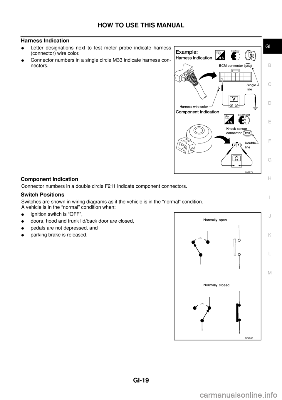
Harness Indication
lLetter designations next to test meter probe indicate harness
(connector) wire color.
lConnector numbers in a single circle M33 indicate harness con-
nectors.
Component Indication
Connector numbers in a double circle F211 indicate component connectors.
Switch Positions
Switches are shown in wiring diagrams as if the vehicle is in the “normal” condition.
A vehicle is in the “normal” condition when:
lignition switch is “OFF”,
ldoors, hood and trunk lid/back door are closed,
lpedals are not depressed, and
lparking brake is released.
AGI070
SGI860
Page 1758 of 3171
IDX-6
ALPHABETICAL INDEX
P
P/SCKT - Wiring diagram ................................WW-57
Park/Neutral position switch ............................EC-342
Park/neutral position switch (A/T) ......................AT-99
Park/neutral position switch (M/T) ........MT-12,MT-19
Parking brake control ...........................................PB-2
Personal lamp ...................................................LT-145
Pilot bushing replacement ..............................EM-111
Piston pin inspection .......................................EM-125
Piston ring inspection ......................................EM-126
Piston to bore clearance .................................EM-129
Planetary carrier (Transfer) ..............................TF-129
PNP/SW - Wiring diagram ...............................EC-343
POWER - Wiring diagram ....................................PG-5
Power seat .........................................................SE-10
Power steering fluid level ..................................MA-37
Power steering gear ...........................................PS-14
Power steering oil pump ....................................PS-25
Power steering system bleeding ..........................PS-6
Power supply routing ...........................................PG-4
Power window ...................................................GW-15
Precations for Leak detection dye ....ATC-14,MTC-14
Precautions (General) ...........................................GI-4
Pre-delivery inspection .......................................MA-5
Pressure plate - See Clutch cover .....................CL-17
Pressure switch 1 ..............................AT-139,AT-156
Pressure switch 2 ............................................AT-154
Pressure switch 3 ..............................AT-134,AT-158
Pressure switch 5 ..............................AT-144,AT-160
Pressure switch 6 ..............................AT-149,AT-162
Pressure test (A/T) .............................................AT-44
Priming pump .....................................................EC-23
Propeller shaft ............................................PR-3,PR-7
Propeller shaft inspection .................................MA-32
Propeller shaft on vehicle service ........................PR-7
Propeller shaft vibration .............................PR-3,PR-7
Q
Quick-glow system ...........................................EC-295
R
R/FOG - Wiring diagram .....................................LT-89
Radiator ................................................CO-11,CO-15
Rear bumper .......................................................EI-17
Rear case (Transfer) ...........................TF-114,TF-120
Rear combination lamp removal and installation ..........
LT-144
Rear cover packing replacement diff. ..............FFD-14
Rear door ..........................................................GW-38
Rear seat ...........................................................SE-29
Rear seat belt ............................................SB-7,SB-9
Rear window .....................................................GW-43
Rear window defogger ......................................GW-47
Refrigerant connection precaution ........ATC-5,MTC-5
Refrigerant discharging evacuating chargingATC-138,
MTC-118
Refrigerant general precaution ............ATC-5,MTC-5
Refrigerant lines ...........ATC-138,ATC-146,ATC-147,
MTC-118
,MTC-126,MTC-127
Refrigerant pressure sensor ............EC-325,ATC-92,
ATC-147
,MTC-85,MTC-127
Refrigeration cycle ...........................ATC-20,MTC-20
Relay box ..........................................................PG-85
Removal and installation (A/T) .........................AT-247
Removal and installation (Transfer) .................TF-111
Reverse idler shaft (M/T) ..................................MT-21
Reverse lamp switch (M/T) - See Back-up lamp switch
(M/T) .....................................................MT-12
,MT-19
Reverse main gear (M/T) ..................................MT-21
Revolution sensor (A/T) .....................AT-103,AT-238
Road wheel size .................................................GI-60
Rocker cover .....................................................EM-56
Room lamp ......................................................LT-145
Room lamp - See Interior lamp ........................LT-145
ROOM/L - Wiring diagram ...............................LT-149
RP/SEN - Wiring diagram ................................EC-326
S
S/SIG - Wiring diagram ....................................EC-348
SCTC/V - Wiring diagram ................................EC-219
SEAT - Wiring diagram ..........................SE-10,SE-11
Seat belt inspection ..............................SB-11,MA-40
Seat belt pre-tensioner ...................................SRS-47
Seat belt pre-tensioner disposal .....................SRS-49
Seat belt, front ...........................................SB-3,SB-5
Seat belt, rear ............................................SB-7,SB-9
Seat, front ..........................................................SE-20
Seat, rear ...........................................................SE-29
Self-diagnosis (Transfer) ...................................TF-49
SHIFT - Wiring diagram ...................................AT-213
Shift control (Transfer) .....................................TF-135
Shift control components (M/T) .........................MT-23
Shift fork (M/T) ..................................................MT-23
Shift lever ..........................................................MT-13
Shift lock system ..............................................AT-212
Shock absorber (front) ....................................FSU-11
Shock absorber (rear) .......................................RSU-6
Side air bag .....................................................SRS-43
Side air bag (satellite) sensor .........................SRS-46
Side curtain air bag .........................................SRS-44
Side trim ..............................................................EI-33
SMJ (super multiple junction) ...........................PG-81
Spare tire size .....................................................GI-60
Speedometer ........................................................DI-4
Spiral cable .....................................................SRS-38
SROOF - Wiring diagram ...................................RF-14
SRS - See Supplemental Restraint System .....SRS-6
SRS - Wiring diagram .....................................SRS-13
SRS Trouble diagnoses ....................................SRS-9
Stabilizer bar (front) ........................................FSU-12
Stall test (A/T) ....................................................AT-43
Standardized relay ............................................PG-79
START - Wiring diagram ....................................SC-28
Start signal .......................................................EC-348
Page 2280 of 3171
DESCRIPTION
MA-5
C
D
E
F
G
H
I
J
K
MA
B
MA
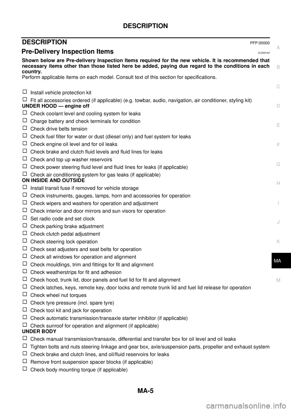
DESCRIPTIONPFP:00000
Pre-Delivery Inspection ItemsELS001K2
Shown below are Pre-delivery Inspection Items required for the new vehicle. It is recommended that
necessary items other than those listed here be added, paying due regard to the conditions in each
country.
Perform applicable items on each model. Consult text of this section for specifications.
Install vehicle protection kit
Fit all accessories ordered (if applicable) (e.g. towbar, audio, navigation, air conditioner, styling kit)
UNDER HOOD — engine off
Check coolant level and cooling system for leaks
Charge battery and check terminals for condition
Check drive belts tension
Check fuel filter for water or dust (diesel only) and fuel system for leaks
Check engine oil level and for oil leaks
Check brake and clutch fluid levels and fluid lines for leaks
Check and top up washer reservoirs
Check power steering fluid level and fluid lines for leaks (if applicable)
Check air conditioning system for gas leaks (if applicable)
ON INSIDE AND OUTSIDE
Install transit fuse if removed for vehicle storage
Check instruments, gauges, lamps, horn and accessories for operation
Check wipers and washers for operation and adjustment
Check interior and door mirrors and sun visors for operation
Set radio code and set clock
Check parking brake adjustment
Check clutch pedal adjustment
Check steering lock operation
Check seat adjusters and seat belts for operation
Check all windows for operation and alignment
Check mouldings, trim and fittings for fit and alignment
Check weatherstrips for fit and adhesion
Check hood, trunk lid, door panels and fuel lid for fit and alignment
Check latches, keys, remote key, door locks and remote trunk lid and fuel lid release for operation
Check wheel nut torques
Check tyre pressure (incl. spare tyre)
Check tool kit and jack for operation
Check automatic transmission/transaxle starter inhibitor (if applicable)
Check sunroof for operation and alignment (if applicable)
UNDER BODY
Check manual transmission/transaxle, differential and transfer box for oil level and oil leaks
Tighten bolts and nuts steering linkage and gear box, axle/suspension parts, propeller and exhaust system
Check brake and clutch lines, and oil/fluid reservoirs for leaks
Remove front suspension spacer blocks (if applicable)
Check body mounting torque (if applicable)