2005 NISSAN NAVARA parking brake
[x] Cancel search: parking brakePage 81 of 3171
TROUBLE DIAGNOSIS
AT-73
D
E
F
G
H
I
J
K
L
MA
B
AT
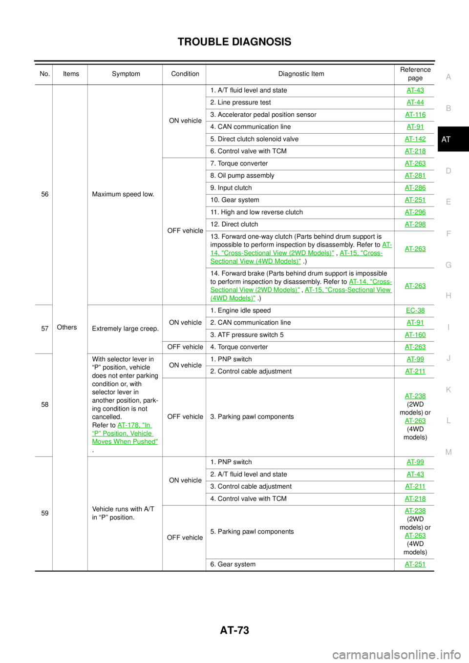
56
OthersMaximum speed low.ON vehicle1. A/T fluid level and stateAT- 4 3
2. Line pressure testAT- 4 4
3. Accelerator pedal position sensorAT- 11 6
4. CAN communication lineAT- 9 1
5. Direct clutch solenoid valveAT-142
6. Control valve with TCMAT-218
OFF vehicle7. Torque converterAT-263
8. Oil pump assemblyAT-281
9. Input clutchAT-286
10. Gear systemAT-251
11. High and low reverse clutchAT-296
12. Direct clutchAT-298
13. Forward one-way clutch (Parts behind drum support is
impossible to perform inspection by disassembly. Refer toAT-
14, "Cross-Sectional View (2WD Models)",AT- 1 5 , "Cross-
SectionalView(4WDModels)".)AT-263
14. Forward brake (Parts behind drum support is impossible
to perform inspection by disassembly. Refer toAT- 1 4 , "
Cross-
Sectional View (2WD Models)",AT- 1 5 , "Cross-Sectional View
(4WD Models)".)AT-263
57 Extremely large creep.ON vehicle1. Engine idle speedEC-382. CAN communication lineAT- 9 1
3. ATF pressure switch 5AT-160
OFF vehicle 4. Torque converterAT-263
58With selector lever in
“P” position, vehicle
does not enter parking
condition or, with
selector lever in
another position, park-
ing condition is not
cancelled.
Refer toAT-178, "
In
“P”Position, Vehicle
Moves When Pushed"
.ON vehicle1. PNP switchAT- 9 9
2. Control cable adjustmentAT- 2 11
OFF vehicle 3. Parking pawl componentsAT-238
(2WD
models) or
AT-263
(4WD
models)
59VehiclerunswithA/T
in “P” position.ON vehicle1. PNP switchAT- 9 9
2. A/T fluid level and stateAT- 4 3
3. Control cable adjustmentAT- 2 11
4. Control valve with TCMAT-218
OFF vehicle5. Parking pawl componentsAT-238
(2WD
models) or
AT-263
(4WD
models)
6. Gear systemAT-251
No. Items Symptom Condition Diagnostic ItemReference
page
Page 528 of 3171
AV-40
TERMINALS AND REFERENCE VALUE FOR CONTROL UNIT
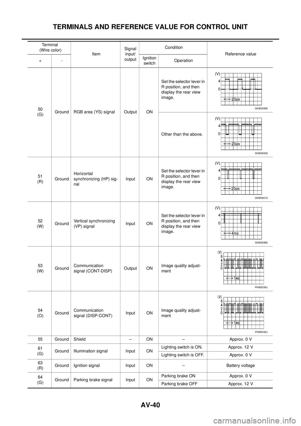
50
(G)Ground RGB area (YS) signal Output ONSet the selector lever in
R position, and then
display the rear view
image.
Other than the above.
51
(R)GroundHorizontal
synchronizing (HP) sig-
nalInput ONSet the selector lever in
R position, and then
display the rear view
image.
52
(W)GroundVertical synchronizing
(VP) signalInput ONSet the selector lever in
R position, and then
display the rear view
image.
53
(W)GroundCommunication
signal (CONT-DISP)Output ONImage quality adjust-
ment
54
(O)GroundCommunication
signal (DISP-CONT)Input ONImage quality adjust-
ment
55 Ground Shield – ON – Approx. 0 V
61
(G)Ground Illumination signal Input ONLighting switch is ON. Approx. 12 V
Lighting switch is OFF. Approx. 0 V
63
(R)Ground Ignition signal Input ON – Battery voltage
64
(G)Ground Parking brake signal Input ONParking brake ON Approx. 0 V
Parking brake OFF Approx. 12 V Terminal
(Wire color)
ItemSignal
input/
outputCondition
Reference value
+-Ignition
switchOperationSKIB3599E
SKIB3600E
SKIB3601E
SKIB3598E
PKIB5039J
PKIB5039J
Page 532 of 3171

AV-44
DIAGNOSIS SYSTEM
DIAGNOSIS SYSTEM
PFP:00000
Navigation System Diagnosis FunctionEKS00Q6H
lThere are 2 diagnosis functions (on board diagnosis and diagnosis using CONSULT-II), and it is neces-
sary to use them properly according to the condition. If the on board diagnosis starts, perform diagnosis
with on board diagnosis. If the on board diagnosis does not start (the cause being that the system is not
started, the switch operation is not activated, etc.), perform diagnosis using CONSULT-II.
lAt on board diagnosis, the NAVI control unit diagnosis function starts by switch operation and the NAVI
control unit performs the diagnosis for each unit of system.
lAt diagnosis using CONSULT-II, the NAVI control unit diagnosis function starts by the communication
between CONSULT-II and NAVI control unit, and the NAVI control unit performs the diagnosis for each
unit of system.
On Bord Self-Diagnosis FunctionEKS00Q6I
DESCRIPTION
lThe on board diagnosis function has a self-diagnosis mode for performing trouble diagnosis automatically
and a Confirmation/Adjustment mode for operating manually.
lSelf-diagnosis mode performs the diagnosis at NAVI control unit, connections between each unit that
composes the system, and connections between NAVI control unit and GPS antenna. It displays the
results on the display.
lConfirmation/Adjustment mode is used to monitor the vehicle signals requiring operation and judgement
by a technician (malfunctions that cannot be automatically judged by the system), the confirmation/adjust-
ment of setting value, the error history of system, and the communication condition of system.
DIAGNOSIS ITEM
Mode Description
Self Diagnosis
lNAVI control unit diagnosis (DVD-ROM drive will not be diagnosed when
no map DVD-ROM is in it.)
lThe connection diagnosis between NAVI control unit and GPS antenna
and the connection diagnosis between NAVI control unit and each unit
can be performed.
Confirma-
tion/Adjust-
mentDisplay DiagnosisThe tint can be confirmed by the color spectrum bar display. The shading
of color can be confirmed by the gradation bar display.
Vehicle SignalsDiagnosis of signals can be performed for vehicle speed, parking brake,
lights, ignition (ignition switch), and reverse.
Speaker Test The connection of a speaker can be confirmed by test tone.
NavigationSteering Angle
AdjustmentWhen there is a difference between the actual turning angle and the vehi-
cle mark turning angle, it can be adjusted.
Speed CalibrationWhen there is a difference between the current location mark and the
actual location, it can be adjusted.
Error HistoryThe system malfunction and its frequency that occurred in the past are dis-
played. When the malfunctioning item is selected, the time and place that
the selected malfunction last occurred are displayed.
Vehicle CAN Diagnosis The transmitting/receiving of CAN communication can be monitored.
AV COMM DiagnosisThe communication condition of each unit that composes the system can
be monitored.
Handsfree PhoneEach setting of hands-free volume adjustment, voice microphone test,
delete hands-free memory can be performed.
Bluetooth Passkey and device name can be confirmed/changed.
Delete Unit Commection Log The connection history and error history of unit can be deleted.
Page 537 of 3171
DIAGNOSIS SYSTEM
AV-49
C
D
E
F
G
H
I
J
L
MA
B
AV
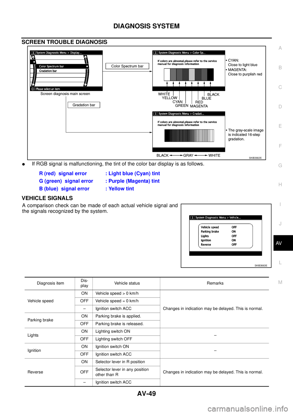
SCREEN TROUBLE DIAGNOSIS
lIf RGB signal is malfunctioning, the tint of the color bar display is as follows.
VEHICLE SIGNALS
Acomparisoncheckcanbemadeofeachactualvehiclesignaland
the signals recognized by the system.
SKIB3662E
R (red) signal error : Light blue (Cyan) tint
G (green) signal error : Purple (Magenta) tint
B (blue) signal error : Yellow tint
SKIB3663E
Diagnosis itemDis-
playVehicle status Remarks
Vehicle speedON Vehicle speed > 0 km/h
Changes in indication may be delayed. This is normal. OFF Vehicle speed = 0 km/h
– Ignition switch ACC
Parking brakeON Parking brake is applied.
OFF Parking brake is released.
LightsON Lighting switch ON
–
OFF Lighting switch OFF
IgnitionON Ignition switch ON
–
OFF Ignition switch ACC
ReverseON Selector lever in R position
Changes in indication may be delayed. This is normal. OFFSelector lever in any position
other than R
– Ignition switch ACC
Page 546 of 3171
AV-58
DIAGNOSIS SYSTEM
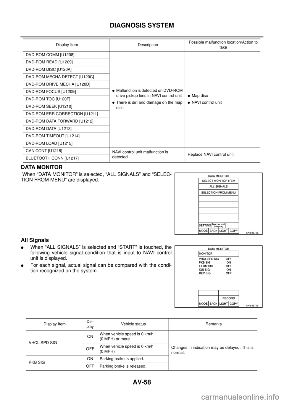
DATA MONITOR
When “DATA MONITOR” is selected, “ALL SIGNALS” and “SELEC-
TION FROM MENU” are displayed.
All Signals
lWhen “ALL SIGNALS” is selected and “START” is touched, the
following vehicle signal condition that is input to NAVI control
unit is displayed.
lFor each signal, actual signal can be compared with the condi-
tion recognized on the system.
DVD-ROM COMM [U1208]
lMalfunctionisdetectedonDVD-ROM
drive pickup lens in NAVI control unit
lThere is dirt and damage on the map
disc
lMap disc
lNAVI control unit DVD-ROM READ [U1209]
DVD-ROM DISC [U120A]
DVD-ROM MECHA DETECT [U120C]
DVD-ROM DRIVE MECHA [U120D]
DVD-ROM FOCUS [U120E]
DVD-ROM TOC [U120F]
DVD-ROM SEEK [U1210]
DVD-ROM ERR CORRECTION [U1211]
DVD-ROM DATA FORWARD [U1212]
DVD-ROM DATA [U1213]
DVD-ROM TIMEOUT [U1214]
DVD-ROM LOAD [U1215]
CAN CONT [U1216]
NAVI control unit malfunction is
detectedReplace NAVI control unit
BLUETOOTH CONN [U1217]Display Item DescriptionPossible malfunction location/Action to
take
SKIB3675E
SKIB3676E
Display ItemDis-
playVehicle status Remarks
VHCL SPD SIGONWhen vehicle speed is 0 km/h
(0 MPH) or more
Changes in indication may be delayed. This is
normal. OFFWhen vehicle speed is 0 km/h
(0 MPH)
PKB SIGON Parking brake is applied.
OFF Parking brake is released.
Page 796 of 3171
BR-10
BRAKE FLUID
BRAKE FLUID
PFP:KN100
On-board InspectionEFS005SI
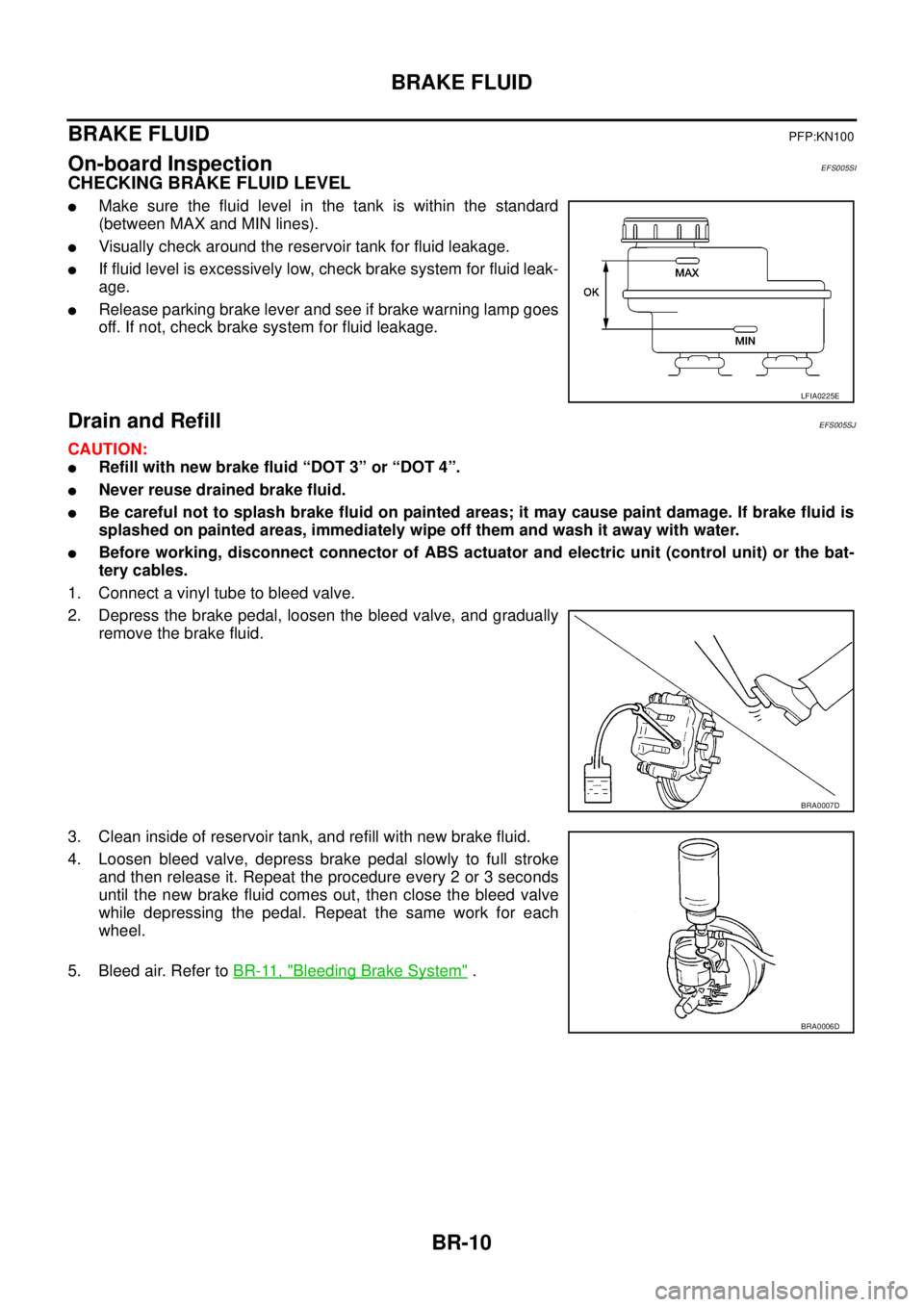
CHECKING BRAKE FLUID LEVEL
lMake sure the fluid level in the tank is within the standard
(between MAX and MIN lines).
lVisually check around the reservoir tank for fluid leakage.
lIf fluid level is excessively low, check brake system for fluid leak-
age.
lRelease parking brake lever and see if brake warning lamp goes
off. If not, check brake system for fluid leakage.
Drain and RefillEFS005SJ
CAUTION:
lRefill with new brake fluid “DOT 3” or “DOT 4”.
lNever reuse drained brake fluid.
lBe careful not to splash brake fluid on painted areas; it may cause paint damage. If brake fluid is
splashed on painted areas, immediately wipe off them and wash it away with water.
lBefore working, disconnect connector of ABS actuator and electric unit (control unit) or the bat-
tery cables.
1. Connect a vinyl tube to bleed valve.
2. Depress the brake pedal, loosen the bleed valve, and gradually
remove the brake fluid.
3. Clean inside of reservoir tank, and refill with new brake fluid.
4. Loosen bleed valve, depress brake pedal slowly to full stroke
and then release it. Repeat the procedure every 2 or 3 seconds
until the new brake fluid comes out, then close the bleed valve
while depressing the pedal. Repeat the same work for each
wheel.
5. Bleed air. Refer toBR-11, "
Bleeding Brake System".
LFIA0225E
BRA0007D
BRA0006D
Page 816 of 3171
BR-30
REAR DRUM BRAKE
REAR DRUM BRAKE
PFP:43206
ComponentsEFS006AF
WARNING:
Clean dust on drum and back plate with a vacuum dust collector to minimize the hazard of air borne
particles or other materials.
CAUTION:
Make sure parking brake lever is released completely.
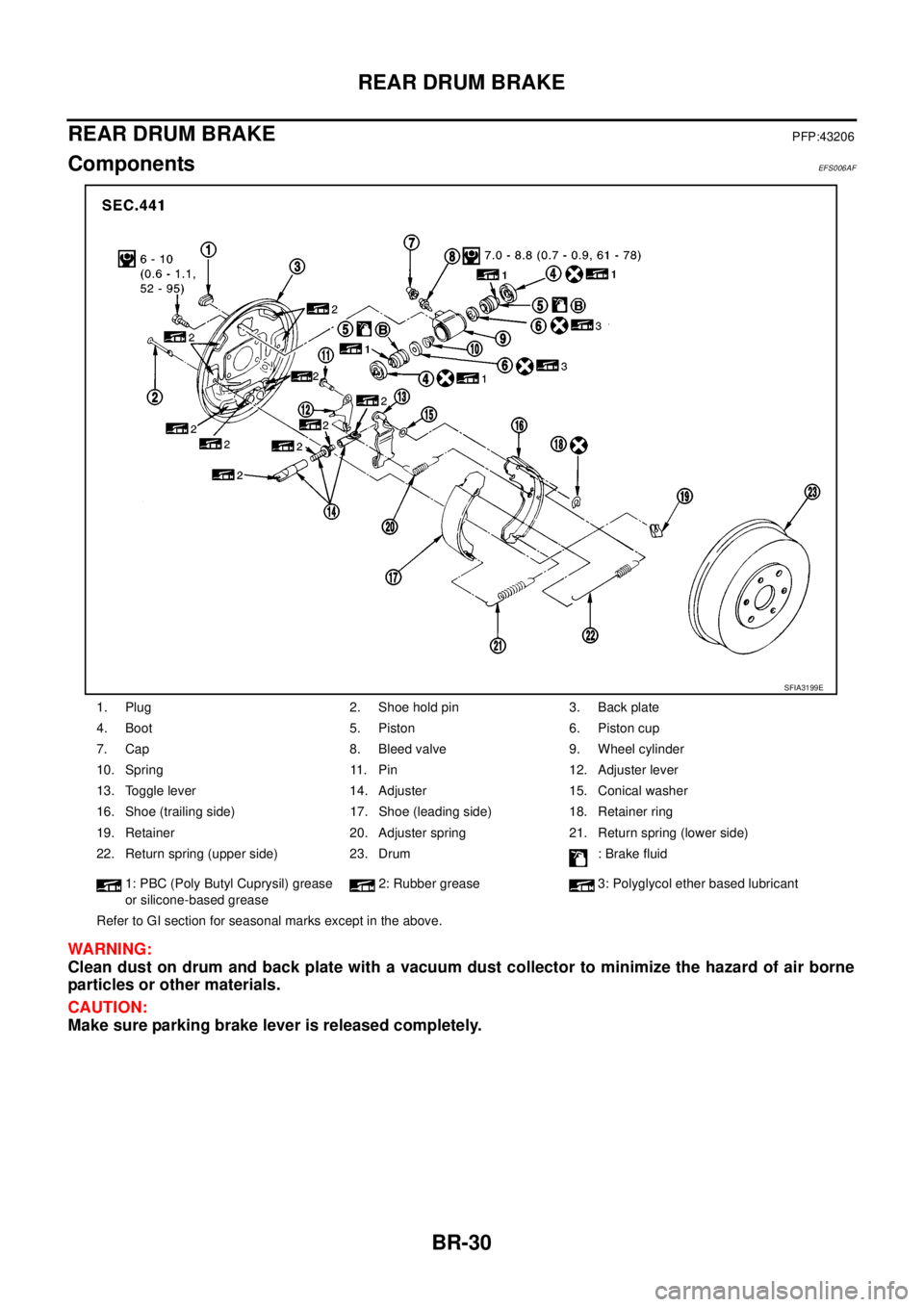
1. Plug 2. Shoe hold pin 3. Back plate
4. Boot 5. Piston 6. Piston cup
7. Cap 8. Bleed valve 9. Wheel cylinder
10. Spring 11. Pin 12. Adjuster lever
13. Toggle lever 14. Adjuster 15. Conical washer
16. Shoe (trailing side) 17. Shoe (leading side) 18. Retainer ring
19. Retainer 20. Adjuster spring 21. Return spring (lower side)
22. Return spring (upper side) 23. Drum : Brake fluid
1: PBC (Poly Butyl Cuprysil) grease
or silicone-based grease2: Rubber grease 3: Polyglycol ether based lubricant
Refer to GI section for seasonal marks except in the above.
SFIA3199E
Page 817 of 3171
REAR DRUM BRAKE
BR-31
C
D
E
G
H
I
J
K
L
MA
B
BR
Removal and Installation of Drum Brake AssemblyEFS006AG
REMOVAL
1. Remove tyre from the vehicle.
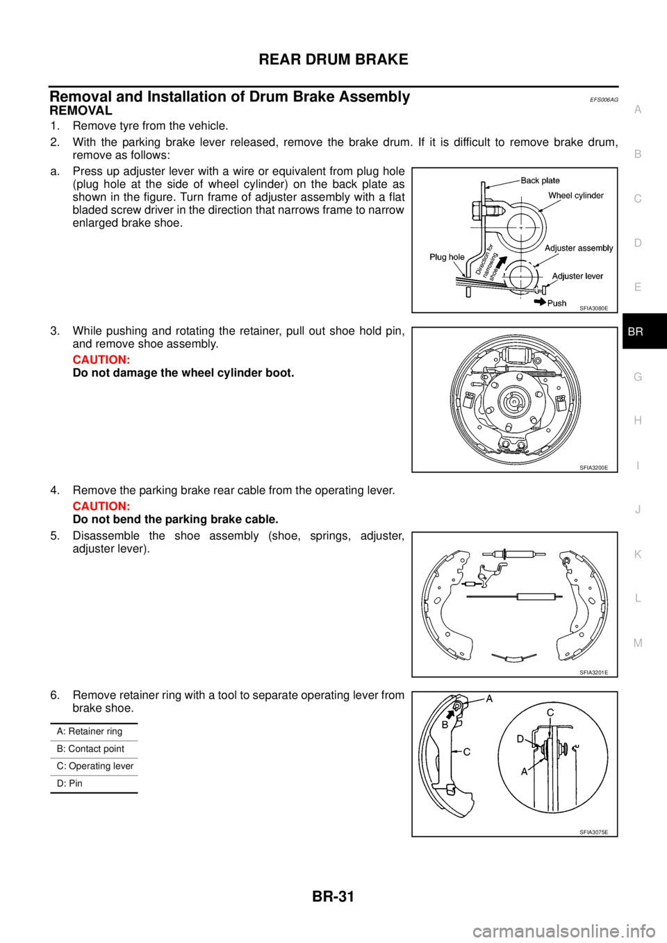
2. With the parking brake lever released, remove the brake drum. If it is difficult to remove brake drum,
remove as follows:
a. Press up adjuster lever with a wire or equivalent from plug hole
(plug hole at the side of wheel cylinder) on the back plate as
shown in the figure. Turn frame of adjuster assembly with a flat
bladed screw driver in the direction that narrows frame to narrow
enlarged brake shoe.
3. While pushing and rotating the retainer, pull out shoe hold pin,
and remove shoe assembly.
CAUTION:
Do not damage the wheel cylinder boot.
4. Remove the parking brake rear cable from the operating lever.
CAUTION:
Do not bend the parking brake cable.
5. Disassemble the shoe assembly (shoe, springs, adjuster,
adjuster lever).
6. Remove retainer ring with a tool to separate operating lever from
brake shoe.
SFIA3080E
SFIA3200E
SFIA3201E
A: Retainer ring
B: Contact point
C: Operating lever
D: Pin
SFIA3075E