Page 2526 of 3171
PARKING BRAKE CONTROL
PB-3
C
D
E
G
H
I
J
K
L
MA
B
PB
ComponentsEFS005S5
LHD MODEL
SFIA3203E
1. Device assembly 2. Parking brake switch 3. Adjusting nut
4. Front cable 5. Equalizer 6. Rear cable (LH)
7. Rear cable (RH) :Multi-purpose grease
Refer to GI section for symbol marks except in the above.
Page 2527 of 3171
PB-4
PARKING BRAKE CONTROL
RHD MODEL
Removal and InstallationEFS005S6
REMOVAL
1. Release parking brake lever.
2. Remove center console. Refer toIP-16, "
CENTER CONSOLE".
3. Disconnect parking brake switch connector.
4. Remove adjusting nut (1).
5. Remove device assembly mounting bolt and remove device
assembly from vehicle.
6. Remove front cable mounting nuts and remove front cable from
vehicle.
7. Remove tyre from vehicle.
8. Remove center muffler. Refer toEX-2, "
EXHAUST SYSTEM".
9. Remove propeller shaft. Refer toPR-7, "
REAR PROPELLER
SHAFT".
10. Remove rear cable from toggle lever.
11. Remove rear cable mounting nuts, bolts, and remove rear cable
assembly from vehicle.
SFIA3204E
1. Device assembly 2. Parking brake switch 3. Adjusting nut
4. Front cable 5. Equalizer 6. Rear cable (LH)
7. Rear cable (RH) : Multi-purpose grease
Refer to GI section for symbol marks except in the above.
SFIA2989E
Page 2528 of 3171
PARKING BRAKE CONTROL
PB-5
C
D
E
G
H
I
J
K
L
MA
B
PB
INSTALLATION
1. Installation is in the reverse order of the removal. Refer toPB-3, "Components"for tightening torque.
2. Adjust parking brake. Refer toPB-2, "
ADJUSTMENT".
Page 2529 of 3171
PB-6
SERVICE DATA AND SPECIFICATIONS (SDS)
SERVICE DATA AND SPECIFICATIONS (SDS)
PFP:00030
Parking Brake ControlEFS005SA
Control typeCenter lever
Number of notches [under a force of 196 N (20 kg, 44 lb)] 9 -10 notches
Number of notches when warning lamp switch comes on. 1 notch
Page 2624 of 3171

REAR PROPELLER SHAFT
PR-9
C
E
F
G
H
I
J
K
L
MA
B
PR
REMOVAL
1. Move the A/T select lever to the N position or set M/T shift lever to neutral position.
2. Release the parking brake.
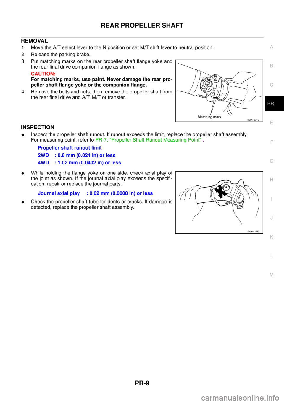
3. Put matching marks on the rear propeller shaft flange yoke and
the rear final drive companion flange as shown.
CAUTION:
For matching marks, use paint. Never damage the rear pro-
peller shaft flange yoke or the companion flange.
4. Remove the bolts and nuts, then remove the propeller shaft from
the rear final drive and A/T, M/T or transfer.
INSPECTION
lInspect the propeller shaft runout. If runout exceeds the limit, replace the propeller shaft assembly.
For measuring point, refer toPR-7, "
Propeller Shaft Runout Measuring Point".
lWhile holding the flange yoke on one side, check axial play of
the joint as shown. If the journal axial play exceeds the specifi-
cation, repair or replace the journal parts.
lCheck the propeller shaft tube for dents or cracks. If damage is
detected, replace the propeller shaft assembly.
PDIA1071E
Propeller shaft runout limit
2WD : 0.6 mm (0.024 in) or less
4WD : 1.02 mm (0.0402 in) or less
Journal axial play : 0.02 mm (0.0008 in) or less
LDIA0117E
Page 2635 of 3171

PS-8
STEERING WHEEL
STEERING WHEEL
PFP:48430
On-Vehicle Inspection and ServiceEGS001LG
CHECKING CONDITION OF INSTALLATION
lCheck installation conditions of steering gear assembly, front suspension assembly, axle and steering col-
umn assembly.
lCheck if movement exists when steering wheel is moved up and down, to the left and right and to the axial
direction.
lCheck steering gear assembly mounting bolts and nuts for looseness. Refer toPS-14, "COMPONENT".
CHECKING STEERING WHEEL PLAY
lTurn steering wheel so that front wheels come to the straight-ahead position. Start engine and lightly turn
steering wheel to the left and right until front wheels start to move. Measure steering wheel movement on
the outer circumference.
lWhen the measurement value is outside the standard value, check backlash for each joint of steering col-
umn assembly and installation condition of steering gear assembly.
CHECKING NEUTRAL POSITION STEERING WHEEL
lMake sure that steering gear assembly, steering column assembly and steering wheel are installed in the
correct position.
lPerform neutral position inspection after wheel alignment. Refer toFSU-7, "Front Wheel Alignment".
lSet vehicle to the straight-ahead position and confirm steering wheel is in the neutral position.
lLoosen outer socket lock nut and turn inner socket to left and right equally to make fine adjustment if
steering wheel is not in the neutral position.
CHECKING STEERING WHEEL TURNING FORCE
1. Park vehicle on a level and dry surface, set parking brake.
2. Start engine.
3. Bring power steering fluid up to adequate operating temperature. [Make sure temperature of fluid is
approximately 50 to 80°C(122to176°F).]
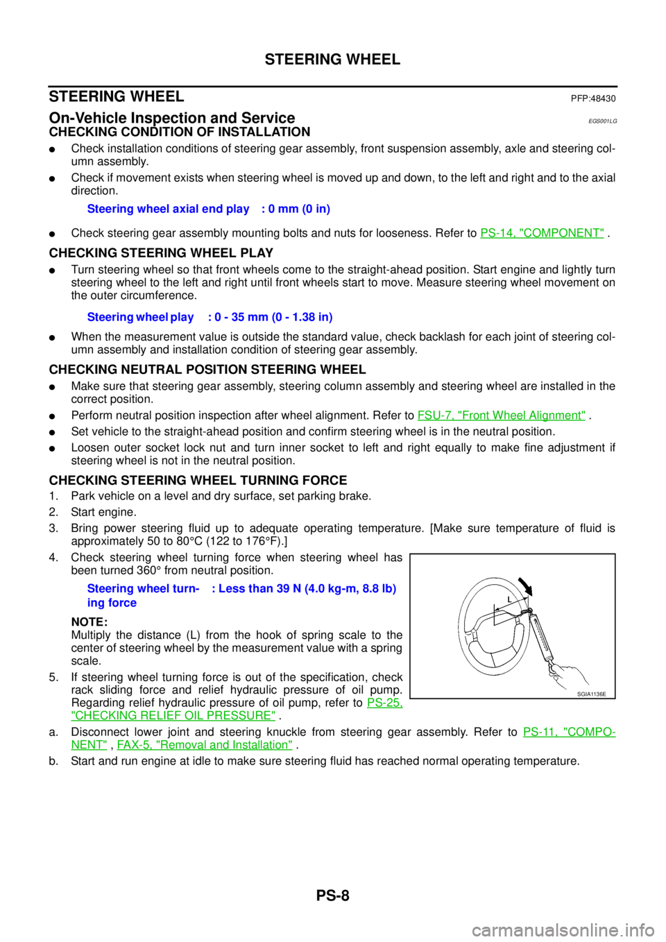
4. Check steering wheel turning force when steering wheel has
been turned 360°from neutral position.
NOTE:
Multiply the distance (L) from the hook of spring scale to the
center of steering wheel by the measurement value with a spring
scale.
5. If steering wheel turning force is out of the specification, check
rack sliding force and relief hydraulic pressure of oil pump.
Regarding relief hydraulic pressure of oil pump, refer toPS-25,
"CHECKING RELIEF OIL PRESSURE".
a. Disconnect lower joint and steering knuckle from steering gear assembly. Refer toPS-11, "
COMPO-
NENT",FAX-5, "Removal and Installation".
b. Start and run engine at idle to make sure steering fluid has reached normal operating temperature.Steering wheel axial end play : 0 mm (0 in)
Steering wheel play : 0 - 35 mm (0 - 1.38 in)
Steering wheel turn-
ing force: Less than 39 N (4.0 kg-m, 8.8 lb)
SGIA1136E
Page 2671 of 3171
![NISSAN NAVARA 2005 Repair Workshop Manual RAX-8
[M226]
AXLE SHAFT
REMOVAL
1. Remove the wheel.
2. Remove the rear brake drum. Refer toBR-31, "
Removal and Installation of Drum Brake Assembly".
3. Remove four lock nuts and spring washers secur NISSAN NAVARA 2005 Repair Workshop Manual RAX-8
[M226]
AXLE SHAFT
REMOVAL
1. Remove the wheel.
2. Remove the rear brake drum. Refer toBR-31, "
Removal and Installation of Drum Brake Assembly".
3. Remove four lock nuts and spring washers secur](/manual-img/5/57362/w960_57362-2670.png)
RAX-8
[M226]
AXLE SHAFT
REMOVAL
1. Remove the wheel.
2. Remove the rear brake drum. Refer toBR-31, "
Removal and Installation of Drum Brake Assembly".
3. Remove four lock nuts and spring washers securing the axle
shaft retainer to the rear axle case.
4. Using a wire, suspend the baffle plate to the sub frame.
NOTE:
Brake hose and brake cable do not need to be disconnected from the baffle plate and wheel cylinder.
CAUTION:
lBe careful not to deform brake tube.
lDo not bend the parking brake cable.
lWhile removing drum, never depress brake pedal because the piston will pop out.
5. Remove the axle shaft assembly from the rear axle case as
shown.
6. Using a puller remove the bearing cup from the rear axle case.
CAUTION:
lThe axle shaft bearing cup may stay in place in the axle
shaft housing. Remove the cup carefully so as not to
damage the inner surface of the axle shaft housing.
7. Usingapuller,removetheaxleshaftguideandoilsealfromthe
rear axle case.
NOTE:
Rear final drive oil will spill while removing the oil seal. Use a drain pan under the rear axle case to drain
oil.
10. Baffle plate 11. Bearing cup 12. Axle shaft guide
13. Oil seal 14. Breather 15. Rear axle case
LDIA0112E
WDIA0182E
Tool number : ST33290001
Tool number : ST33290001
MDIB9050E
Page 2829 of 3171

SB-12
SEAT BELTS
SEAT BELT RETRACTOR ON-VEHICLE CHECK
Emergency Locking Retractors (ELR)
NOTE:
All seat belt retractors are of the Emergency Locking Retractors (ELR) type. In an emergency (sudden stop)
the retractor will lock and prevent the belt from extending any further.
Check the seat belt retractors using the following test(s) to determine if a retractor assembly is operating prop-
erly.
ELR Function Stationary Check
Grasp the shoulder belt and pull forward quickly. The retractor should lock and prevent the belt from extending
further.
ELR Function Moving Check
WARNING:
Perform the following test in a safe, open area clear of other vehicles and obstructions (for example, a
large, empty parking lot). Road surface must be paved and dry. DO NOT perform the following test on
wet or gravel roads or on public streets and highways. This could result in an accident and serious
personal injury. The driver and passenger must be prepared to brace themselves in the event the
retractor does not lock.
1. Fasten drivers seat belt. Buckle a passenger into the seat for the belt that is to be tested.
2. Proceed to the designated safe area.
3. Drive the vehicle at approximately 16 km/h (10 MPH). Notify any passengers of a pending sudden stop.
The driver and passenger must be prepared to brace themselves in the event the retractor does not lock.
Apply brakes firmly and make a very hard stop.
During stop, seat belts should lock and not be extended. If the seat belt retractor assembly does not lock, per-
form the retractor off-vehicle check.
SEAT BELT RETRACTOR OFF-VEHICLE CHECK
1. Remove the seat belt retractor assembly.
2. Slowly pull out belt while tilting the retractor assembly forward from the mounted position without twisting
the retractor assembly as shown in the illustration.