2005 NISSAN NAVARA oil level
[x] Cancel search: oil levelPage 249 of 3171
ON-VEHICLE SERVICE
AT-241
D
E
F
G
H
I
J
K
L
MA
B
AT
Installation
CAUTION:
After completing installation, check A/T fluid leakage, A/T fluid level and A/T position. Refer toAT- 1 2 ,
"Checking A/T Fluid",AT- 2 11 , "Checking of A/T Position".
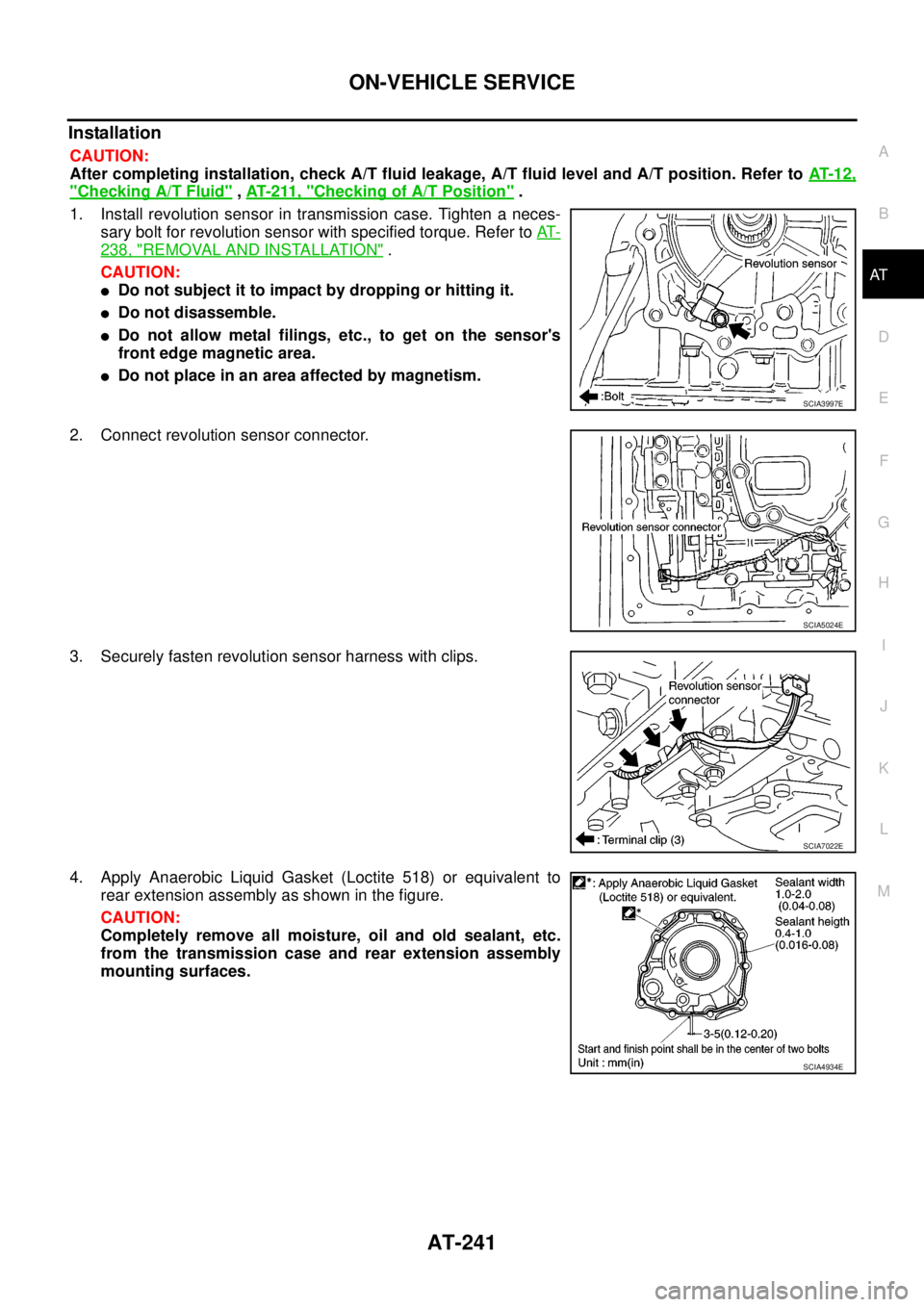
1. Install revolution sensor in transmission case. Tighten a neces-
sary bolt for revolution sensor with specified torque. Refer toAT-
238, "REMOVAL AND INSTALLATION".
CAUTION:
lDo not subject it to impact by dropping or hitting it.
lDo not disassemble.
lDo not allow metal filings, etc., to get on the sensor's
front edge magnetic area.
lDo not place in an area affected by magnetism.
2. Connect revolution sensor connector.
3. Securely fasten revolution sensor harness with clips.
4. Apply Anaerobic Liquid Gasket (Loctite 518) or equivalent to
rear extension assembly as shown in the figure.
CAUTION:
Completely remove all moisture, oil and old sealant, etc.
from the transmission case and rear extension assembly
mounting surfaces.
SCIA3997E
SCIA5024E
SCIA7022E
SCIA4934E
Page 480 of 3171
ATC-146
REFRIGERANT LINES
BREAK-IN OPERATION
When replacing compressor clutch assembly, always conduct the break-in operation. This is done by engag-
ing and disengaging the clutch about 30 times. Break-in operation raises the level of transmitted torque.
Removal and Installation for High-pressure Flexible A/C HoseEJS006CP
REMOVAL
1. Remove the front left wheel and tire assembly. Refer toWT-5, "Rotation".
2. Remove the front left mud guard.
3. Remove the front left splash shield.
4. Discharge the refrigerant. Refer toATC-138, "
HFC-134a (R-134a) Service Procedure".
5. Remove the high-pressure flexible A/C hose. Refer toATC-140, "
Components".
CAUTION:
Cap or wrap the joint of the pipe with suitable material such as vinyl tape to avoid the entry of air.
INSTALLATION
Installation is in the reverse order of removal.
Refer toATC-140, "
Components".
CAUTION:
lReplace the O-ring of the high-pressure flexible A/C hose with a new one, then apply compressor
oil to it for installation.
lAfter charging refrigerant, check for leaks.
Removal and Installation for High-pressure A/C PipeEJS006CQ
REMOVAL
1. Remove the front right wheel and tire assembly. Refer toWT-5, "Rotation".
2. Remove the front right mud guard.
3. Remove the front right splash shield.
4. Discharge the refrigerant. Refer toATC-138, "
HFC-134a (R-134a) Service Procedure".
5. Remove the low pressure A/C pipe. Refer toATC-147, "
Removal and Installation for Low-pressure A/C
Pipe".
6. Remove the high-pressure A/C pipe. Refer toATC-146, "
Removal and Installation for High-pressure A/C
Pipe".
CAUTION:
Cap or wrap the joint of the pipe with suitable material such as vinyl tape to avoid the entry of air.
INSTALLATION
Installation is in the reverse order of removal.
Refer toATC-140, "
Components".
CAUTION:
lReplace the O-ring of the high-pressure A/C pipe with a new one, then apply compressor oil to it
for installation.
lAfter charging refrigerant, check for leaks.
Removal and Installation for Low-pressure Flexible A/C HoseEJS006CR
REMOVAL
1. Remove the front right wheel and tire assembly. Refer toWT-5, "Rotation".
2. Remove the front right mud guard.
3. Remove the front right splash shield.
4. Discharge the refrigerant. Refer toATC-138, "
HFC-134a (R-134a) Service Procedure".
CAUTION:
Cap or wrap the joint of the pipe with suitable material such as vinyl tape to avoid the entry of air.
5. Remove the low-pressure flexible A/C hose. Refer toATC-140, "
Components".
INSTALLATION
Installation is in the reverse order of removal.
Refer toATC-140, "
Components".
Page 825 of 3171
![NISSAN NAVARA 2005 Repair Workshop Manual PRECAUTIONS
BRC-3
[ABS]
C
D
E
G
H
I
J
K
L
MA
B
BRC
[ABS]PRECAUTIONSPFP:00001
Precautions for Supplemental Restraint System (SRS) “AIR BAG” and “SEAT
BELT PRE-TENSIONER”
EFS006DM
The Supplement NISSAN NAVARA 2005 Repair Workshop Manual PRECAUTIONS
BRC-3
[ABS]
C
D
E
G
H
I
J
K
L
MA
B
BRC
[ABS]PRECAUTIONSPFP:00001
Precautions for Supplemental Restraint System (SRS) “AIR BAG” and “SEAT
BELT PRE-TENSIONER”
EFS006DM
The Supplement](/manual-img/5/57362/w960_57362-824.png)
PRECAUTIONS
BRC-3
[ABS]
C
D
E
G
H
I
J
K
L
MA
B
BRC
[ABS]PRECAUTIONSPFP:00001
Precautions for Supplemental Restraint System (SRS) “AIR BAG” and “SEAT
BELT PRE-TENSIONER”
EFS006DM
The Supplemental Restraint System such as “AIR BAG” and “SEAT BELT PRE-TENSIONER”, used along
with a front seat belt, helps to reduce the risk or severity of injury to the driver and front passenger for certain
types of collision. Information necessary to service the system safely is included in the SRS and SB section of
this Service Manual.
WARNING:
lTo avoid rendering the SRS inoperative, which could increase the risk of personal injury or death
in the event of a collision which would result in air bag inflation, all maintenance must be per-
formed by an authorized NISSAN/INFINITI dealer.
lImproper maintenance, including incorrect removal and installation of the SRS, can lead to per-
sonal injury caused by unintentional activation of the system. For removal of Spiral Cable and Air
Bag Module, see the SRS section.
lDo not use electrical test equipment on any circuit related to the SRS unless instructed to in this
Service Manual. SRS wiring harnesses can be identified by yellow and/or orange harnesses or
harness connectors.
Precautions for Brake SystemEFS005TG
lRecommended fluid is brake fluid “DOT 3” or “DOT 4”.
lNever reuse drained brake fluid.
lBe careful not to splash brake fluid on painted areas.If brake fluid is splashed, wipe it off and flush area
with water immediately.
lNever use mineral oils such as gasoline or kerosene. They will ruin rubber parts of the hydraulic system.
lUse flare nut wrench when removing flare nuts, and use a flare
nut torque wrench when tighten flare nuts.
lBrake system is an important safety part.If a brake fluid leak is
detected, always disassemble the affected part.If a malfunction
is detected, replace part with new one.
lBefore working, turn ignition switch OFF and disconnect con-
nector of ABS actuator and electric unit (control unit) or the bat-
tery cables.
lWhen installing brake tube and hose, be sure to torque.
WARNING:
Clean brake pads and shoes with a waster cloth, then wipe with
a dust collector.
Precautions for Brake ControlEFS005TH
lJust after starting vehicle after ignition switch ON, brake pedal may vibrate or motor operating noise may
be heard from engine room. This is a normal status of operation check.
lStopping distance may be longer than that of vehicles without ABS when vehicle drives on rough, gravel,
or snow-covered (fresh, deep snow) roads.
lWhen an error is indicated by ABS or another warning lamp, collect all necessary information from cus-
tomer (what symptoms are present under what conditions) and check for simple causes before starting
diagnostic servicing. Besides electrical system inspection, check brake booster operation, brake fluid
level, and fluid leaks.
lIf tyre size and type are used in an improper combination, or brake pads are not Genuine NISSAN parts,
stopping distance or steering stability may deteriorate.
lIf there is a radio, antenna, or antenna lead-in wire (including wiring) near control module, ABS function
may have a malfunction or error.
lIf aftermarket parts (car stereo, CD player, etc.) have been installed, check for incidents such as harness
pinches, open circuits, and improper wiring.
SBR820BA
Page 908 of 3171
CO-24
THERMOSTAT AND WATER PIPING
Removal and Installation
EBS01E6X
WARNING:
Do not remove radiator cap and/or reservoir tank cap when engine is hot. Serious burns could occur
from high pressure engine coolant escaping from radiator and/or reservoir tank.
REMOVAL
1. Remove front engine undercover and middle engine undercover. Refer toEI-15, "FRONT BUMPER".
2. Drain engine coolant from radiator drain plug at the bottom of radiator, and from water drain plug at the
side of cylinder block. Refer toCO-7, "
Changing Engine Coolant"andEM-110, "CYLINDER BLOCK".
CAUTION:
Perform this step when engine is cold.
3. Remove engine cover. Refer toEM-20, "
INTAKE MANIFOLD".
4. Disconnect radiator hoses (upper and lower) from engine side. Refer toCO-11, "
RADIATOR".
5. Remove air inlet pipe and air duct between air cleaner case and turbocharger. Refer toEM-15, "
AIR
CLEANER AND AIR DUCT"andEM-28, "TURBO CHARGER".
6. Remove water outlet, water inlet and thermostat.
7. Remove thermostat housing.
8. Disconnect heater return hose and water hoses at heater return pipe side, and remove heater return pipe.
9. Remove oil level gauge guide mounting bolt, vacuum hoses (to turbocharger boost control solenoid valve)
and spill hose. Refer toEM-36, "
OIL PAN AND OIL STRAINER",EM-20, "INTAKE MANIFOLD"andEM-
44, "INJECTION TUBE AND FUEL INJECTOR".
10. Disconnect water hoses (to EGR cooler) (A/T models), vacuum hoses and heater feed hose at heater
feed pipe side, and remove heater feed pipe. Refer toEM-20, "
INTAKE MANIFOLD".
INSPECTION AFTER REMOVAL
Thermostat
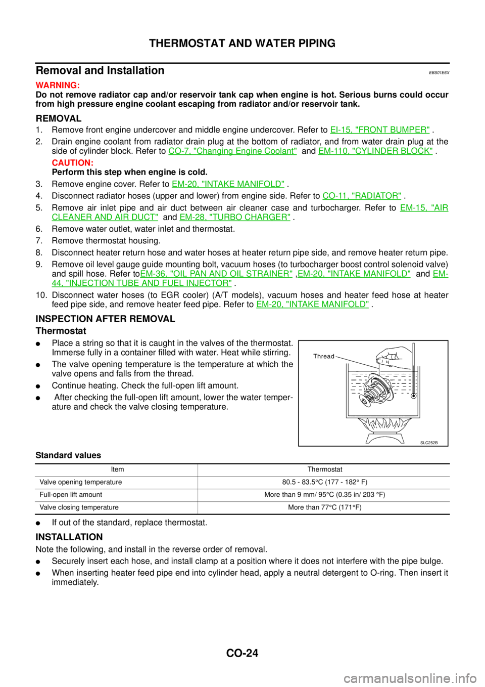
lPlace a string so that it is caught in the valves of the thermostat.
Immerse fully in a container filled with water. Heat while stirring.
lThe valve opening temperature is the temperature at which the
valve opens and falls from the thread.
lContinue heating. Check the full-open lift amount.
lAfter checking the full-open lift amount, lower the water temper-
ature and check the valve closing temperature.
Standard values
lIf out of the standard, replace thermostat.
INSTALLATION
Note the following, and install in the reverse order of removal.
lSecurely insert each hose, and install clamp at a position where it does not interfere with the pipe bulge.
lWhen inserting heater feed pipe end into cylinder head, apply a neutral detergent to O-ring. Then insert it
immediately.
SLC252B
Item Thermostat
Valve opening temperature 80.5 - 83.5°C (177 - 182°F)
Full-open lift amount More than 9 mm/ 95°C (0.35 in/ 203°F)
Valve closing temperature More than 77°C(171°F)
Page 911 of 3171

DI-1
DRIVER INFORMATION SYSTEM
K ELECTRICAL
CONTENTS
C
D
E
F
G
H
I
J
L
M
SECTIONDI
A
B
DI
DRIVER INFORMATION SYSTEM
PRECAUTION ............................................................ 3
Precautions for Supplemental Restraint System
(SRS)“AIRBAG”and“SEATBELTPRE-TEN-
SIONER” .................................................................. 3
Wiring Diagrams and Trouble Diagnosis .................. 3
COMBINATION METERS ........................................... 4
System Description .................................................. 4
UNIFIED METER CONTROL UNIT ...................... 4
POWER SUPPLY AND GROUND CIRCUIT ........ 4
SPEEDOMETER ................................................... 4
TACHOMETER ..................................................... 4
WATER TEMPERATURE GAUGE ........................ 4
FUEL GAUGE ....................................................... 5
ODO/TRIP METER ............................................... 5
TRIP COMPUTER ................................................ 5
ENGINE OIL MAINTENANCE INFORMATION..... 6
METER ILLUMINATION CONTROL ..................... 6
CLOCK .................................................................. 6
AMBIENT AIR TEMPERATURE INDICATION ...... 6
Component Parts and Harness Connector Location..... 7
Arrangement of Combination Meter ......................... 8
Internal Circuit .......................................................... 9
Wiring Diagram — METER — ................................ 10
Terminals and Reference Value for Combination
Meter ...................................................................... 12
Self-Diagnosis Mode of Combination Meter ........... 13
FUNCTION .......................................................... 13
OPERATION PROCEDURE ............................... 13
TEST ITEM ......................................................... 13
CONSULT-II Function (METER) ............................. 15
CONSULT-II BASIC OPERATION ....................... 15
SELF-DIAG RESULTS ........................................ 16
DATA MONITOR ................................................. 17
Trouble Diagnosis .................................................. 18
HOW TO PERFORM TROUBLE DIAGNOSIS ... 18
PRELIMINARY CHECK ...................................... 19
Symptom Chart ...................................................... 19
Power Supply and Ground Circuit Inspection ........ 19
Vehicle Speed Signal Inspection ............................ 20
Engine Speed Signal Inspection ............................ 21Engine Coolant Temperature Signal Inspection ..... 21
Fuel Level Sensor Signal Inspection ...................... 22
Ambient Sensor Signal Inspection .......................... 24
Fuel Gauge Fluctuates, Indicates Wrong Value, or
Varies ...................................................................... 25
Fuel Gauge Does Not Move to Full position ........... 25
DTC [U1000] CAN Communication Circuit ............. 26
DTC [B2205] Vehicle Speed Circuit ........................ 26
Electrical Components Inspection .......................... 27
FUEL LEVEL SENSOR UNIT CHECK ................ 27
AMBIENT SENSOR CHECK ............................... 27
Removal and Installation of Combination Meter ..... 27
WARNING LAMPS .................................................... 28
System Description ................................................. 28
OIL PRESSURE WARNING LAMP ..................... 28
Component Parts and Harness Connector Location... 28
Schematic ............................................................... 29
Wiring Diagram — WARN — .................................. 30
A/T MODELS ....................................................... 30
M/T MODELS ...................................................... 37
Oil Pressure Warning Lamp Stays Off (Ignition
Switch ON) ............................................................. 44
Oil Pressure Warning Lamp Does Not Turn Off (Oil
Pressure Is Normal) ................................................ 45
Oil Pressure Warning Lamp Keeps Blinking (Oil
Level Is Normal) ..................................................... 46
Component Inspection ............................................ 47
OIL PRESSURE SWITCH ................................... 47
OIL LEVEL SENSOR .......................................... 47
A/T INDICATOR ........................................................ 48
System Description ................................................. 48
Wiring Diagram — AT/IND — ................................. 49
A/T Indicator Does Not Illuminate ........................... 50
WARNING CHIME ..................................................... 51
System Description ................................................. 51
POWER SUPPLY AND GROUND CIRCUIT ....... 51
LIGHT WARNING CHIME ................................... 51
KEY REMINDER WARNING CHIME .................. 51
LOW-FUEL WARNING CHIME ........................... 51
SEAT BELT WARNING CHIME ........................... 52
Page 929 of 3171
COMBINATION METERS
DI-19
C
D
E
F
G
H
I
J
L
MA
B
DI
PRELIMINARY CHECK
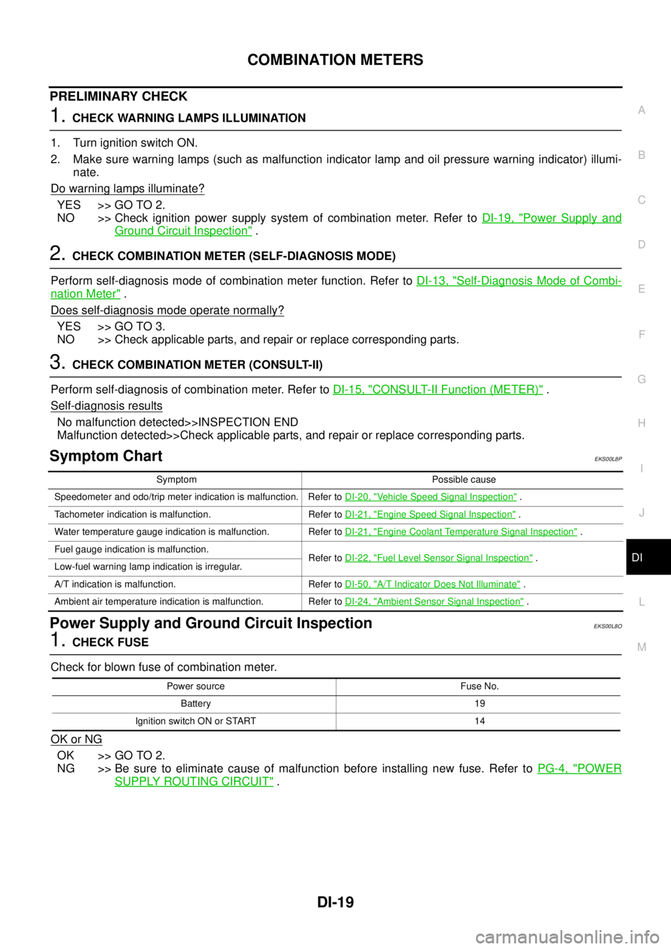
1.CHECK WARNING LAMPS ILLUMINATION
1. Turn ignition switch ON.
2. Make sure warning lamps (such as malfunction indicator lamp and oil pressure warning indicator) illumi-
nate.
Do warning lamps illuminate?
YES >> GO TO 2.
NO >> Check ignition power supply system of combination meter. Refer toDI-19, "
Power Supply and
Ground Circuit Inspection".
2.CHECK COMBINATION METER (SELF-DIAGNOSIS MODE)
Perform self-diagnosis mode of combination meter function. Refer toDI-13, "
Self-Diagnosis Mode of Combi-
nation Meter".
Does self-diagnosis mode operate normally?
YES >> GO TO 3.
NO >> Check applicable parts, and repair or replace corresponding parts.
3.CHECK COMBINATION METER (CONSULT-II)
Perform self-diagnosis of combination meter. Refer toDI-15, "
CONSULT-II Function (METER)".
Self-diagnosis results
No malfunction detected>>INSPECTION END
Malfunction detected>>Check applicable parts, and repair or replace corresponding parts.
Symptom ChartEKS00L8P
Power Supply and Ground Circuit InspectionEKS00L8O
1.CHECK FUSE
Check for blown fuse of combination meter.
OK or NG
OK >> GO TO 2.
NG >> Be sure to eliminate cause of malfunction before installing new fuse. Refer toPG-4, "
POWER
SUPPLY ROUTING CIRCUIT".
Symptom Possible cause
Speedometer and odo/trip meter indication is malfunction. Refer toDI-20, "
Vehicle Speed Signal Inspection".
Tachometer indication is malfunction. Refer toDI-21, "
Engine Speed Signal Inspection".
Water temperature gauge indication is malfunction. Refer toDI-21, "
Engine Coolant Temperature Signal Inspection".
Fuel gauge indication is malfunction.
Refer toDI-22, "
Fuel Level Sensor Signal Inspection".
Low-fuel warning lamp indication is irregular.
A/T indication is malfunction. Refer toDI-50, "
A/T Indicator Does Not Illuminate".
Ambient air temperature indication is malfunction. Refer toDI-24, "
Ambient Sensor Signal Inspection".
Power source Fuse No.
Battery 19
Ignition switch ON or START 14
Page 938 of 3171
DI-28
WARNING LAMPS
WARNING LAMPS
PFP:24814
System DescriptionEKS00MHA
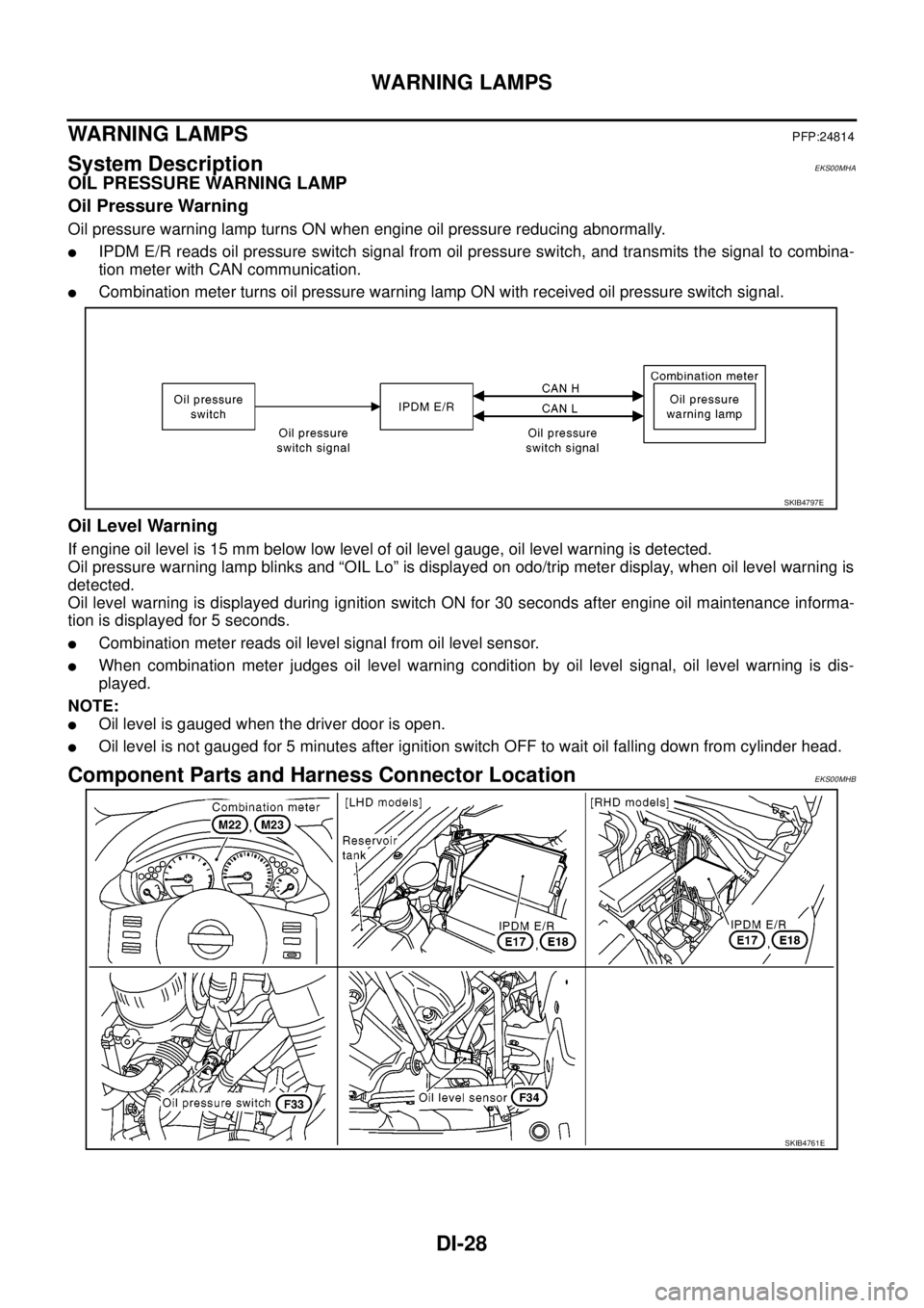
OIL PRESSURE WARNING LAMP
Oil Pressure Warning
Oil pressure warning lamp turns ON when engine oil pressure reducing abnormally.
lIPDM E/R reads oil pressure switch signal from oil pressure switch, and transmits the signal to combina-
tion meter with CAN communication.
lCombination meter turns oil pressure warning lamp ON with received oil pressure switch signal.
Oil Level Warning
If engine oil level is 15 mm below low level of oil level gauge, oil level warning is detected.
Oil pressure warning lamp blinks and “OIL Lo” is displayed on odo/trip meter display, when oil level warning is
detected.
Oil level warning is displayed during ignition switch ON for 30 seconds after engine oil maintenance informa-
tion is displayed for 5 seconds.
lCombination meter reads oil level signal from oil level sensor.
lWhen combination meter judges oil level warning condition by oil level signal, oil level warning is dis-
played.
NOTE:
lOil level is gauged when the driver door is open.
lOil level is not gauged for 5 minutes after ignition switch OFF to wait oil falling down from cylinder head.
Component Parts and Harness Connector LocationEKS00MHB
SKIB4797E
SKIB4761E
Page 956 of 3171
DI-46
WARNING LAMPS
5.CHECK IPDM E/R (CONSULT-II)
Perform self-diagnosis of IPDM E/R. Refer toPG-16, "
CONSULT-II Function (IPDM E/R)".
Self-diagnosis results
No malfunction detected>>Replace combination meter.
Malfunction detected>> Check applicable parts, and repair or replace corresponding parts.
Oil Pressure Warning Lamp Keeps Blinking (Oil Level Is Normal)EKS00MM6
NOTE:
For engine oil level inspection, refer toLU-5, "
ENGINE OIL LEVEL".
If combination meter detects that oil level sensor is open or short circuit, oil level warning is displayed.
1.CHECK OIL LEVEL SENSOR
1. Turn ignition switch OFF.
2. Disconnect oil level sensor connector.
3. Check oil level sensor. Refer toDI-47, "
OIL LEVEL SENSOR".
OK or NG
OK >> GO TO 2.
NG >> Replace oil level sensor.
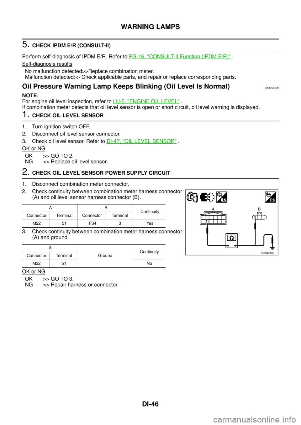
2.CHECK OIL LEVEL SENSOR POWER SUPPLY CIRCUIT
1. Disconnect combination meter connector.
2. Check continuity between combination meter harness connector
(A) and oil level sensor harness connector (B).
3. Check continuity between combination meter harness connector
(A) and ground.
OK or NG
OK >> GO TO 3.
NG >> Repair harness or connector.
AB
Continuity
Connector Terminal Connector Terminal
M22 51 F34 3 Yes
A
GroundContinuity
Connector Terminal
M22 51 No
SKIB4799E