2005 NISSAN NAVARA oil level
[x] Cancel search: oil levelPage 957 of 3171
WARNING LAMPS
DI-47
C
D
E
F
G
H
I
J
L
MA
B
DI
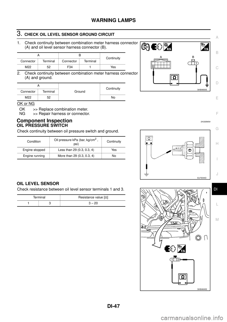
3.CHECK OIL LEVEL SENSOR GROUND CIRCUIT
1. Check continuity between combination meter harness connector
(A) and oil level sensor harness connector (B).
2. Check continuity between combination meter harness connector
(A) and ground.
OK or NG
OK >> Replace combination meter.
NG >> Repair harness or connector.
Component InspectionEKS00M54
OIL PRESSURE SWITCH
Check continuity between oil pressure switch and ground.
OIL LEVEL SENSOR
Check resistance between oil level sensor terminals 1 and 3.
AB
Continuity
Connector Terminal Connector Terminal
M22 52 F34 1 Yes
A
GroundContinuity
Connector Terminal
M22 52 No
SKIB4800E
ConditionOil pressure kPa (bar, kg/cm2,
psi)Continuity
Engine stopped Less than 29 (0.3, 0.3, 4) Yes
Engine running More than 29 (0.3, 0.3, 4) No
ELF0044D
Terminal Resistance value [W]
13 3–20
SKIB4845E
Page 1113 of 3171
DTC P0217 ENGINE OVER TEMPERATURE
EC-133
C
D
E
F
G
H
I
J
K
L
MA
EC
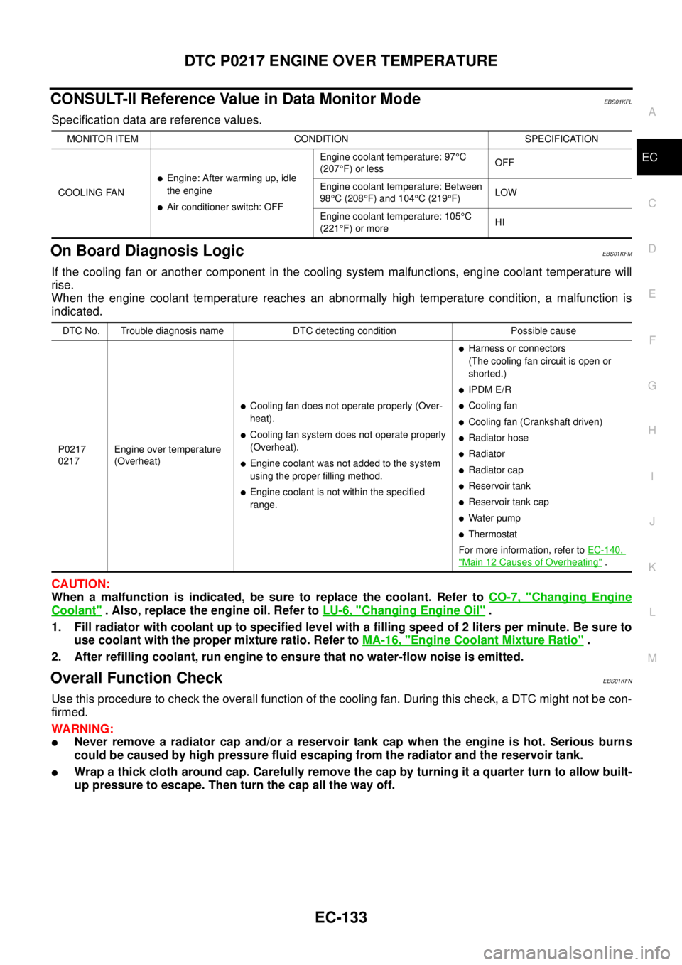
CONSULT-II Reference Value in Data Monitor ModeEBS01KFL
Specification data are reference values.
On Board Diagnosis LogicEBS01KFM
If the cooling fan or another component in the cooling system malfunctions, engine coolant temperature will
rise.
When the engine coolant temperature reaches an abnormally high temperature condition, a malfunction is
indicated.
CAUTION:
When a malfunction is indicated, be sure to replace the coolant. Refer toCO-7, "
Changing Engine
Coolant". Also, replace the engine oil. Refer toLU-6, "Changing Engine Oil".
1. Fill radiator with coolant up to specified level with a filling speed of 2 liters per minute. Be sure to
use coolant with the proper mixture ratio. Refer toMA-16, "
Engine Coolant Mixture Ratio".
2. After refilling coolant, run engine to ensure that no water-flow noise is emitted.
Overall Function CheckEBS01KFN
Use this procedure to check the overall function of the cooling fan. During this check, a DTC might not be con-
firmed.
WARNING:
lNever remove a radiator cap and/or a reservoir tank cap when the engine is hot. Serious burns
could be caused by high pressure fluid escaping from the radiator and the reservoir tank.
lWrap a thick cloth around cap. Carefully remove the cap by turning it a quarter turn to allow built-
up pressure to escape. Then turn the cap all the way off.
MONITOR ITEM CONDITION SPECIFICATION
COOLING FAN
lEngine: After warming up, idle
the engine
lAir conditioner switch: OFFEngine coolant temperature: 97°C
(207°F) or lessOFF
Engine coolant temperature: Between
98°C (208°F) and 104°C(219°F)LOW
Engine coolant temperature: 105°C
(221°F) or moreHI
DTC No. Trouble diagnosis name DTC detecting condition Possible cause
P0217
0217Engine over temperature
(Overheat)
lCooling fan does not operate properly (Over-
heat).
lCooling fan system does not operate properly
(Overheat).
lEngine coolant was not added to the system
using the proper filling method.
lEngine coolant is not within the specified
range.
lHarness or connectors
(The cooling fan circuit is open or
shorted.)
lIPDM E/R
lCooling fan
lCooling fan (Crankshaft driven)
lRadiator hose
lRadiator
lRadiator cap
lReservoir tank
lReservoir tank cap
lWater pump
lThermostat
For more information, refer toEC-140,
"Main 12 Causes of Overheating".
Page 1403 of 3171
INTAKE MANIFOLD
EM-21
C
D
E
F
G
H
I
J
K
L
MA
EM
lRefer toGI-10, "Components"for symbol marks except in the above.
Removal and InstallationEBS01EJF
REMOVAL
WARNING:
To avoid the danger of being scalded, do not drain engine coolant when engine is hot.
1. Drain engine coolant. Refer toCO-7, "
Changing Engine Coolant".
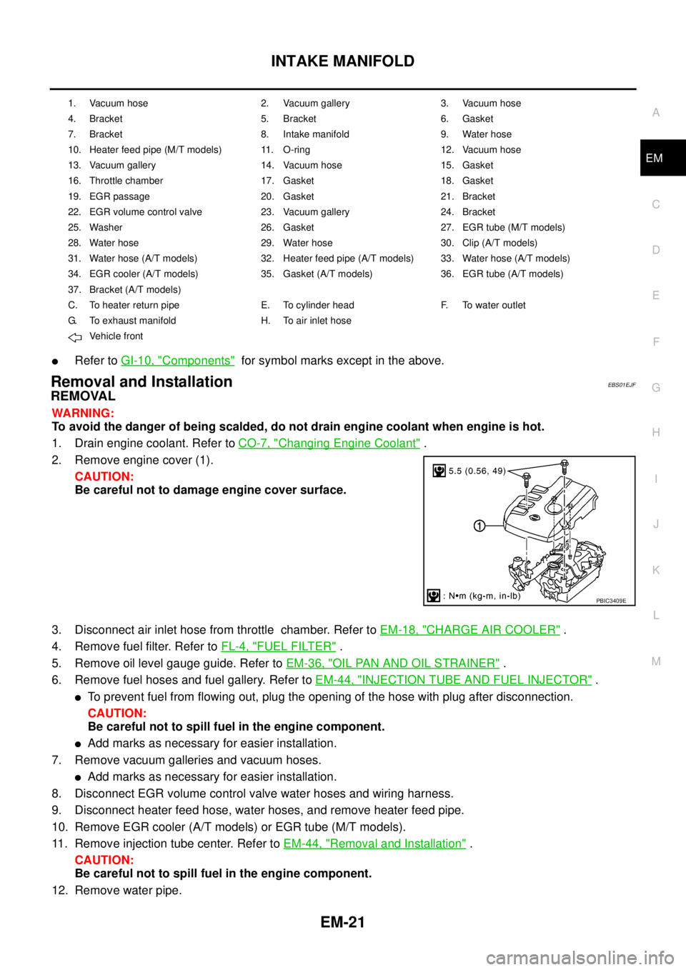
2. Remove engine cover (1).
CAUTION:
Be careful not to damage engine cover surface.
3. Disconnect air inlet hose from throttle chamber. Refer toEM-18, "
CHARGE AIR COOLER".
4. Remove fuel filter. Refer toFL-4, "
FUEL FILTER".
5. Remove oil level gauge guide. Refer toEM-36, "
OIL PAN AND OIL STRAINER".
6. Remove fuel hoses and fuel gallery. Refer toEM-44, "
INJECTION TUBE AND FUEL INJECTOR".
lTo prevent fuel from flowing out, plug the opening of the hose with plug after disconnection.
CAUTION:
Be careful not to spill fuel in the engine component.
lAdd marks as necessary for easier installation.
7. Remove vacuum galleries and vacuum hoses.
lAdd marks as necessary for easier installation.
8. Disconnect EGR volume control valve water hoses and wiring harness.
9. Disconnect heater feed hose, water hoses, and remove heater feed pipe.
10. Remove EGR cooler (A/T models) or EGR tube (M/T models).
11. Remove injection tube center. Refer toEM-44, "
Removal and Installation".
CAUTION:
Be careful not to spill fuel in the engine component.
12. Remove water pipe.
1. Vacuum hose 2. Vacuum gallery 3. Vacuum hose
4. Bracket 5. Bracket 6. Gasket
7. Bracket 8. Intake manifold 9. Water hose
10. Heater feed pipe (M/T models) 11. O-ring 12. Vacuum hose
13. Vacuum gallery 14. Vacuum hose 15. Gasket
16. Throttle chamber 17. Gasket 18. Gasket
19. EGR passage 20. Gasket 21. Bracket
22. EGR volume control valve 23. Vacuum gallery 24. Bracket
25. Washer 26. Gasket 27. EGR tube (M/T models)
28. Water hose 29. Water hose 30. Clip (A/T models)
31. Water hose (A/T models) 32. Heater feed pipe (A/T models) 33. Water hose (A/T models)
34. EGR cooler (A/T models) 35. Gasket (A/T models) 36. EGR tube (A/T models)
37. Bracket (A/T models)
C. To heater return pipe E. To cylinder head F. To water outlet
G. To exhaust manifold H. To air inlet hose
Vehicle front
PBIC3409E
Page 1414 of 3171
EM-32
TURBO CHARGER
Turbocharger Boost Control Actuator
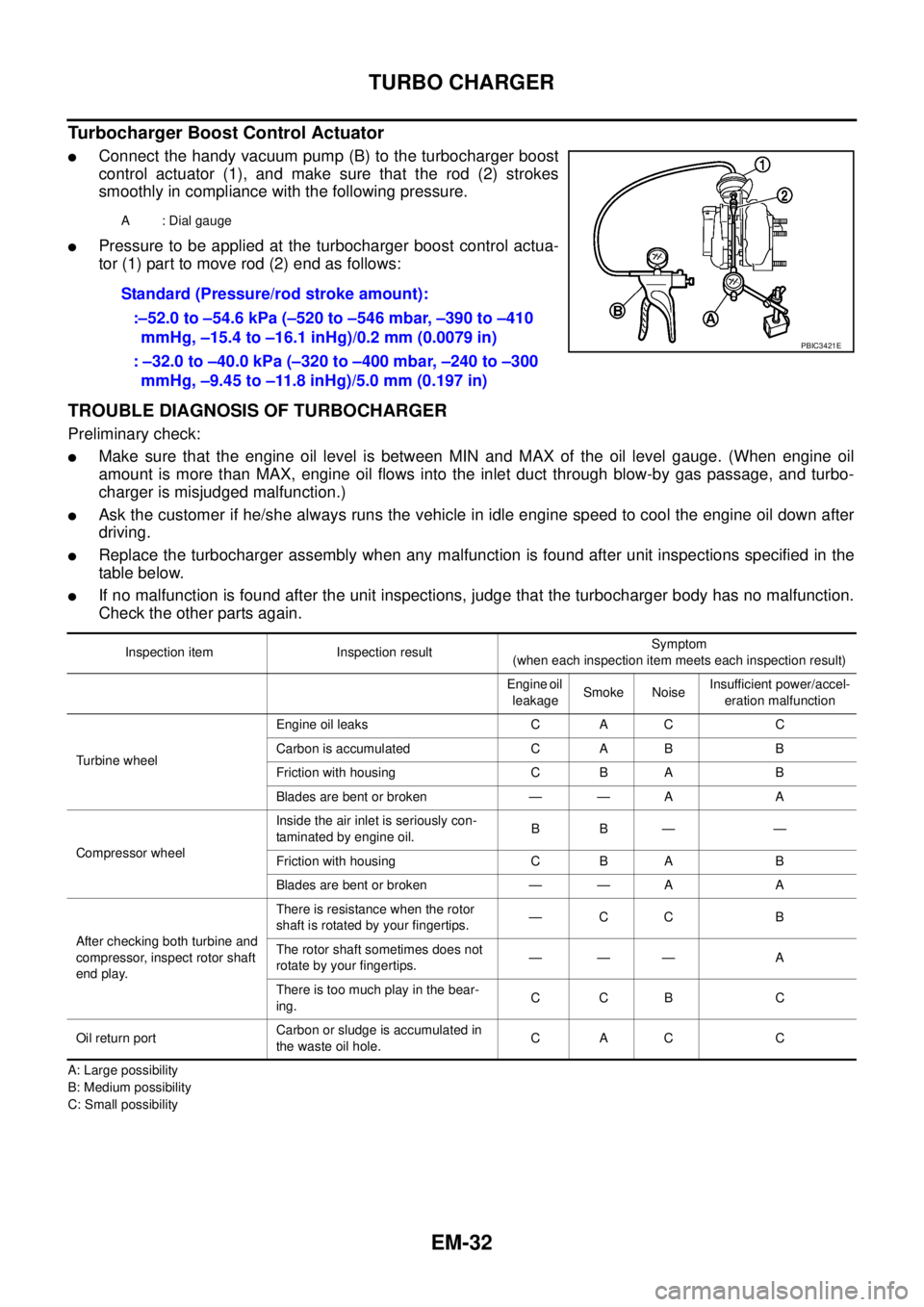
lConnect the handy vacuum pump (B) to the turbocharger boost
control actuator (1), and make sure that the rod (2) strokes
smoothly in compliance with the following pressure.
lPressure to be applied at the turbocharger boost control actua-
tor (1) part to move rod (2) end as follows:
TROUBLE DIAGNOSIS OF TURBOCHARGER
Preliminary check:
lMake sure that the engine oil level is between MIN and MAX of the oil level gauge. (When engine oil
amount is more than MAX, engine oil flows into the inlet duct through blow-by gas passage, and turbo-
charger is misjudged malfunction.)
lAsk the customer if he/she always runs the vehicle in idle engine speed to cool the engine oil down after
driving.
lReplace the turbocharger assembly when any malfunction is found after unit inspections specified in the
table below.
lIf no malfunction is found after the unit inspections, judge that the turbocharger body has no malfunction.
Check the other parts again.
A: Large possibility
B: Medium possibility
C: Small possibilityA : Dial gauge
Standard (Pressure/rod stroke amount):
:–52.0 to –54.6 kPa (–520 to –546 mbar, –390 to –410
mmHg, –15.4 to –16.1 inHg)/0.2 mm (0.0079 in)
: –32.0 to –40.0 kPa (–320 to –400 mbar, –240 to –300
mmHg, –9.45 to –11.8 inHg)/5.0 mm (0.197 in)
PBIC3421E
Inspection item Inspection resultSymptom
(when each inspection item meets each inspection result)
Engine oil
leakageSmoke NoiseInsufficient power/accel-
eration malfunction
Turbine wheelEngine oil leaks C A C C
Carbon is accumulated C A B B
Friction with housing C B A B
Blades are bent or broken — — A A
Compressor wheelInside the air inlet is seriously con-
taminated by engine oil.BB— —
Friction with housing C B A B
Blades are bent or broken — — A A
After checking both turbine and
compressor, inspect rotor shaft
end play.There is resistance when the rotor
shaft is rotated by your fingertips.—CC B
The rotor shaft sometimes does not
rotate by your fingertips.——— A
There is too much play in the bear-
ing.CCB C
Oil return portCarbon or sludge is accumulated in
the waste oil hole.CAC C
Page 1418 of 3171
EM-36
OIL PAN AND OIL STRAINER
OIL PAN AND OIL STRAINER
P F P : 1111 0
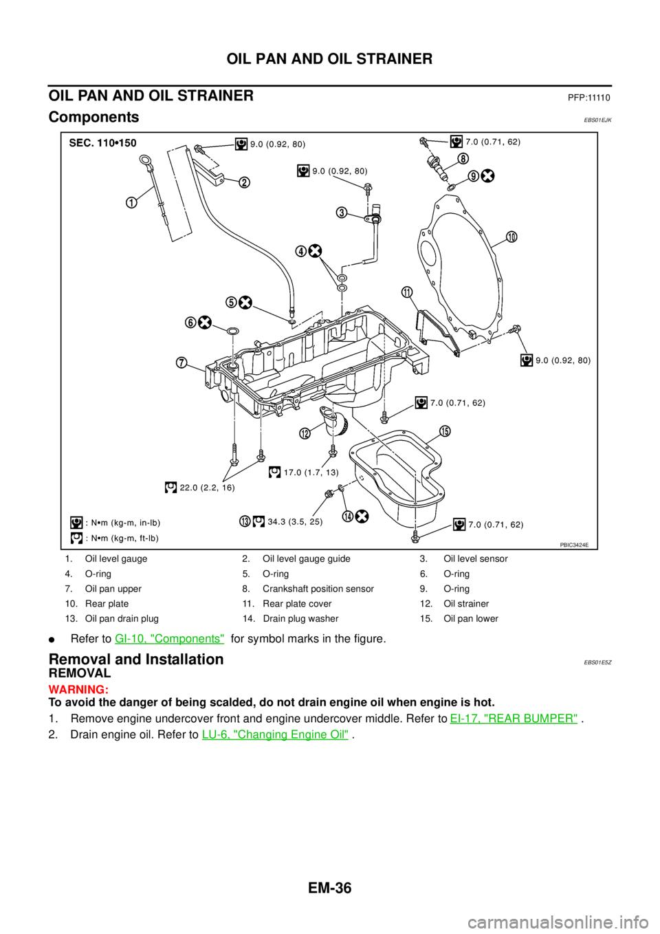
ComponentsEBS01EJK
lRefer toGI-10, "Components"for symbol marks in the figure.
Removal and InstallationEBS01E5Z
REMOVAL
WARNING:
To avoid the danger of being scalded, do not drain engine oil when engine is hot.
1. Remove engine undercover front and engine undercover middle. Refer toEI-17, "
REAR BUMPER".
2. Drain engine oil. Refer toLU-6, "
Changing Engine Oil".
1. Oil level gauge 2. Oil level gauge guide 3. Oil level sensor
4. O-ring 5. O-ring 6. O-ring
7. Oil pan upper 8. Crankshaft position sensor 9. O-ring
10. Rear plate 11. Rear plate cover 12. Oil strainer
13. Oil pan drain plug 14. Drain plug washer 15. Oil pan lower
PBIC3424E
Page 1419 of 3171
OIL PAN AND OIL STRAINER
EM-37
C
D
E
F
G
H
I
J
K
L
MA
EM
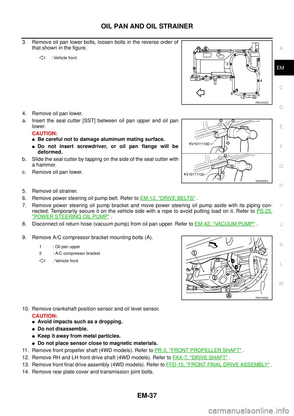
3. Remove oil pan lower bolts, loosen bolts in the reverse order of
that shown in the figure.
4. Remove oil pan lower.
a. Insert the seal cutter [SST] between oil pan upper and oil pan
lower.
CAUTION:
lBe careful not to damage aluminum mating surface.
lDo not insert screwdriver, or oil pan flange will be
deformed.
b. Slide the seal cutter by tapping on the side of the seal cutter with
a hammer.
c. Remove oil pan lower.
5. Remove oil strainer.
6. Remove power steering oil pump belt. Refer toEM-12, "
DRIVE BELTS".
7. Remove power steering oil pump bracket and move power steering oil pump aside with its piping con-
nected. Temporarily secure it on the vehicle side with a rope to avoid putting load on it. Refer toPS-25,
"POWER STEERING OIL PUMP".
8. Disconnect oil return hose (vacuum pump) from oil pan upper. Refer toEM-42, "
VACUUM PUMP".
9. Remove A/C compressor bracket mounting bolts (A).
10. Remove crankshaft position sensor and oil level sensor.
CAUTION:
lAvoid impacts such as a dropping.
lDo not disassemble.
lKeep it away from metal particles.
lDo not place sensor close to magnetic materials.
11. Remove front propeller shaft (4WD models). Refer toPR-3, "
FRONT PROPELLER SHAFT".
12. Remove RH and LH front drive shaft (4WD models). Refer toFAX-7, "
DRIVE SHAFT".
13. Remove front final drive assembly (4WD models). Refer toFFD-15, "
FRONT FINAL DRIVE ASSEMBLY".
14. Remove rear plate cover and transmission joint bolts.
: Vehicle front
PBIC3425E
SEM365EA
1 : Oil pan upper
2 : A/C compressor bracket
: Vehicle front
PBIC3426E
Page 1422 of 3171
EM-40
OIL PAN AND OIL STRAINER
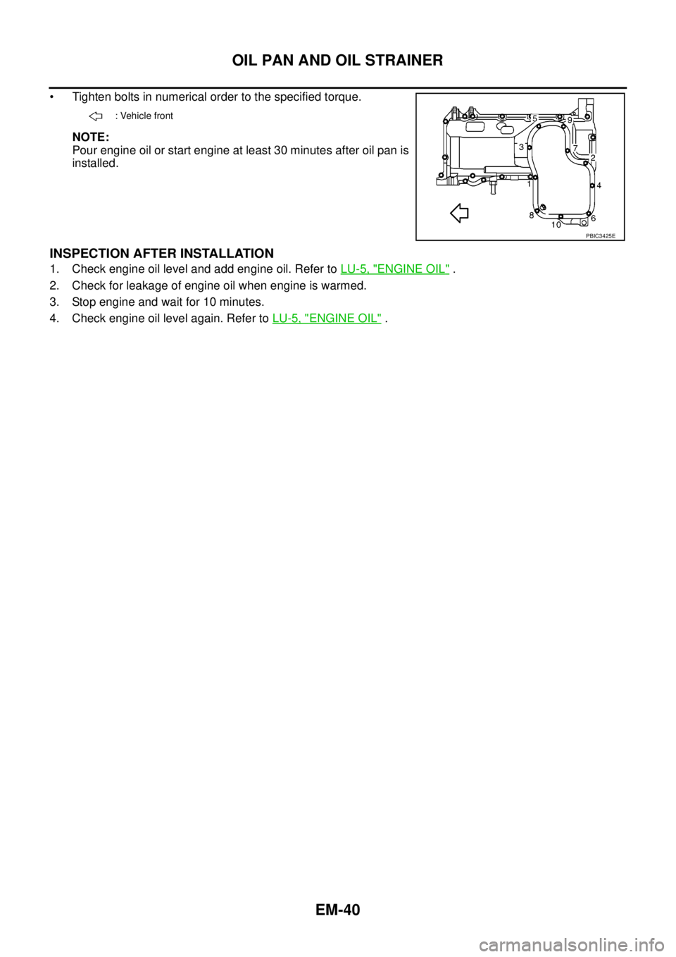
• Tighten bolts in numerical order to the specified torque.
NOTE:
Pour engine oil or start engine at least 30 minutes after oil pan is
installed.
INSPECTION AFTER INSTALLATION
1. Check engine oil level and add engine oil. Refer toLU-5, "ENGINE OIL".
2. Check for leakage of engine oil when engine is warmed.
3. Stop engine and wait for 10 minutes.
4. Check engine oil level again. Refer toLU-5, "
ENGINE OIL".
: Vehicle front
PBIC3425E
Page 1447 of 3171
CAMSHAFT
EM-65
C
D
E
F
G
H
I
J
K
L
MA
EM
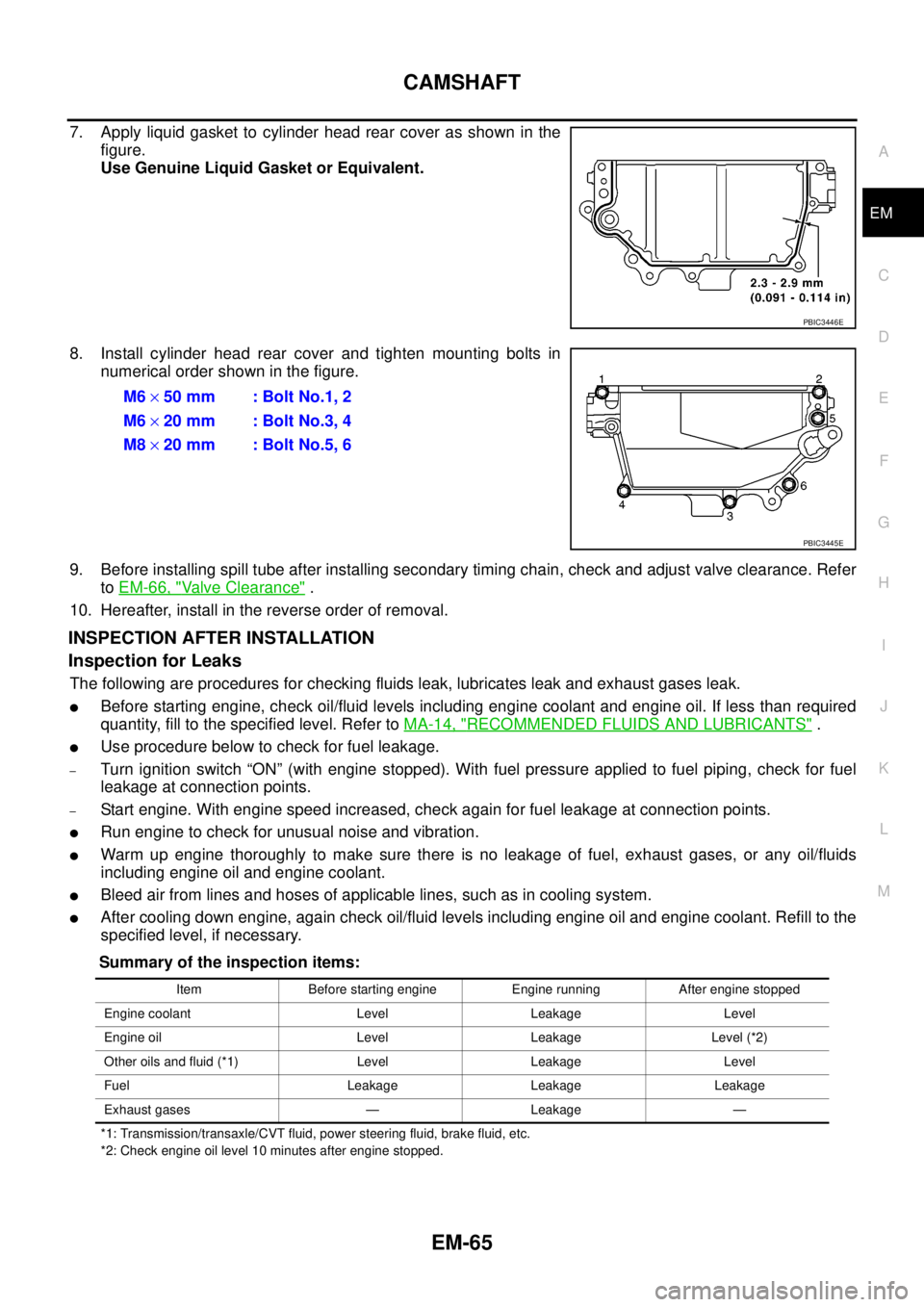
7. Apply liquid gasket to cylinder head rear cover as shown in the
figure.
Use Genuine Liquid Gasket or Equivalent.
8. Install cylinder head rear cover and tighten mounting bolts in
numerical order shown in the figure.
9. Before installing spill tube after installing secondary timing chain, check and adjust valve clearance. Refer
toEM-66, "
Valve Clearance".
10. Hereafter, install in the reverse order of removal.
INSPECTION AFTER INSTALLATION
Inspection for Leaks
The following are procedures for checking fluids leak, lubricates leak and exhaust gases leak.
lBefore starting engine, check oil/fluid levels including engine coolant and engine oil. If less than required
quantity, fill to the specified level. Refer toMA-14, "
RECOMMENDED FLUIDS AND LUBRICANTS".
lUse procedure below to check for fuel leakage.
–Turn ignition switch “ON” (with engine stopped). With fuel pressure applied to fuel piping, check for fuel
leakage at connection points.
–Start engine. With engine speed increased, check again for fuel leakage at connection points.
lRun engine to check for unusual noise and vibration.
lWarm up engine thoroughly to make sure there is no leakage of fuel, exhaust gases, or any oil/fluids
including engine oil and engine coolant.
lBleed air from lines and hoses of applicable lines, such as in cooling system.
lAfter cooling down engine, again check oil/fluid levels including engine oil and engine coolant. Refill to the
specified level, if necessary.
Summary of the inspection items:
*1: Transmission/transaxle/CVT fluid, power steering fluid, brake fluid, etc.
*2: Check engine oil level 10 minutes after engine stopped.
PBIC3446E
M6´50 mm : Bolt No.1, 2
M6´20 mm : Bolt No.3, 4
M8´20 mm : Bolt No.5, 6
PBIC3445E
Item Before starting engine Engine running After engine stopped
Engine coolant Level Leakage Level
Engine oil Level Leakage Level (*2)
Other oils and fluid (*1) Level Leakage Level
Fuel Leakage Leakage Leakage
Exhaust gases — Leakage —