Page 1138 of 3171
EC-158
DTC P0237, P0238 TC BOOST SENSOR
Component Inspection
EBS01KGH
CHECK TURBOCHARGER BOOST SENSOR
1. Remove turbocharger boost sensor with its harness connected.
2. Turn ignition switch ON.
3. Use pump to apply pressure sensor as shown in the figure.
CAUTION:
lAlways calibrate the pressure pump gauge when using it.
lInspection should be done at room temperature [10-30°C(50-86°F)].
4. Check the output voltage between ECM terminal 52 and ground
under the following conditions.
Removal and InstallationEBS01KGI
TURBOCHARGER BOOST SENSOR
Refer toEM-18, "CHARGE AIR COOLER".
Pressure (Relative to atmospheric pressure) Voltage V
0 kPa (0 mbar, 0 mmHg, 0 inHg) Approximately 2.3V
+40 kPa (400 mbar, 300mmHg, 11.81 inHg) Approximately 2.9V
MBIB1093E
Page 1139 of 3171

DTC P0335 CKP SENSOR
EC-159
C
D
E
F
G
H
I
J
K
L
MA
EC
DTC P0335 CKP SENSORPFP:23731
DescriptionEBS01KGJ
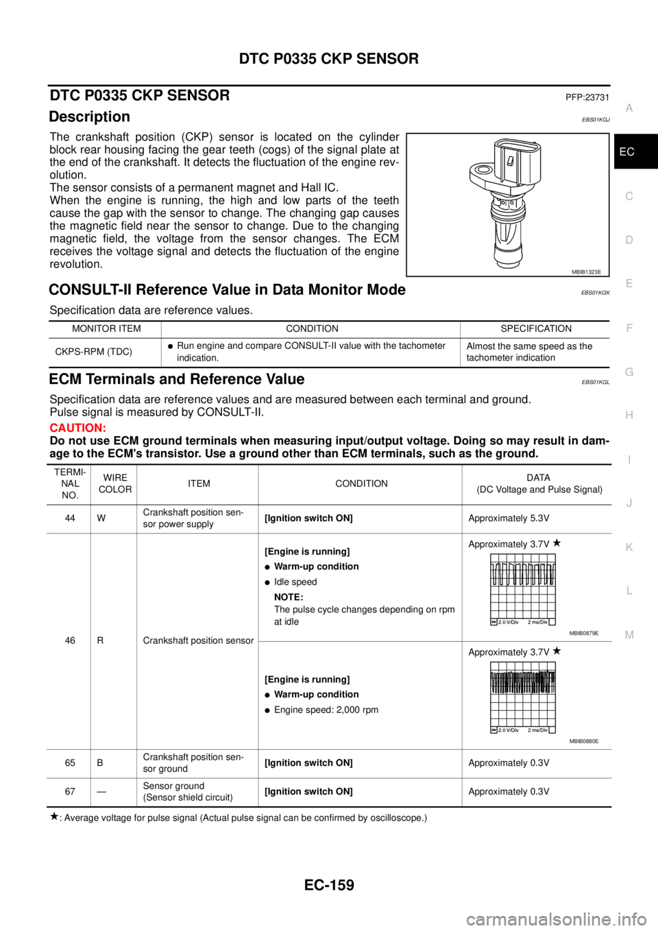
The crankshaft position (CKP) sensor is located on the cylinder
block rear housing facing the gear teeth (cogs) of the signal plate at
the end of the crankshaft. It detects the fluctuation of the engine rev-
olution.
The sensor consists of a permanent magnet and Hall IC.
When the engine is running, the high and low parts of the teeth
cause the gap with the sensor to change. The changing gap causes
the magnetic field near the sensor to change. Due to the changing
magnetic field, the voltage from the sensor changes. The ECM
receives the voltage signal and detects the fluctuation of the engine
revolution.
CONSULT-II Reference Value in Data Monitor ModeEBS01KGK
Specification data are reference values.
ECM Terminals and Reference ValueEBS01KGL
Specification data are reference values and are measured between each terminal and ground.
Pulse signal is measured by CONSULT-II.
CAUTION:
Do not use ECM ground terminals when measuring input/output voltage. Doing so may result in dam-
age to the ECM's transistor. Use a ground other than ECM terminals, such as the ground.
: Average voltage for pulse signal (Actual pulse signal can be confirmed by oscilloscope.)
MBIB1323E
MONITOR ITEM CONDITION SPECIFICATION
CKPS-RPM (TDC)
lRun engine and compare CONSULT-II value with the tachometer
indication.Almost the same speed as the
tachometer indication
TERMI-
NAL
NO.WIRE
COLORITEM CONDITIONDATA
(DC Voltage and Pulse Signal)
44 WCrankshaft position sen-
sor power supply[Ignition switch ON]Approximately 5.3V
46 R Crankshaft position sensor[Engine is running]
lWarm-up condition
lIdle speed
NOTE:
The pulse cycle changes depending on rpm
at idleApproximately 3.7V
[Engine is running]
lWarm-up condition
lEngine speed: 2,000 rpmApproximately 3.7V
65 BCrankshaft position sen-
sor ground[Ignition switch ON]Approximately 0.3V
67 —Sensor ground
(Sensor shield circuit)[Ignition switch ON]Approximately 0.3V
MBIB0879E
MBIB0880E
Page 1140 of 3171

EC-160
DTC P0335 CKP SENSOR
On Board Diagnosis Logic
EBS01KGM
NOTE:
If DTC P0335 is displayed with DTC P0652 or P0653, first perform the trouble diagnosis for DTC P0652
or P0653. Refer toEC-227, "
DTC P0652, P0653 SENSOR POWER SUPPLY".
DTC Confirmation ProcedureEBS01KGN
NOTE:
If DTC Confirmation Procedure has been previously conducted, always turn ignition switch OFF and wait at
least 10 seconds before conducting the next test.
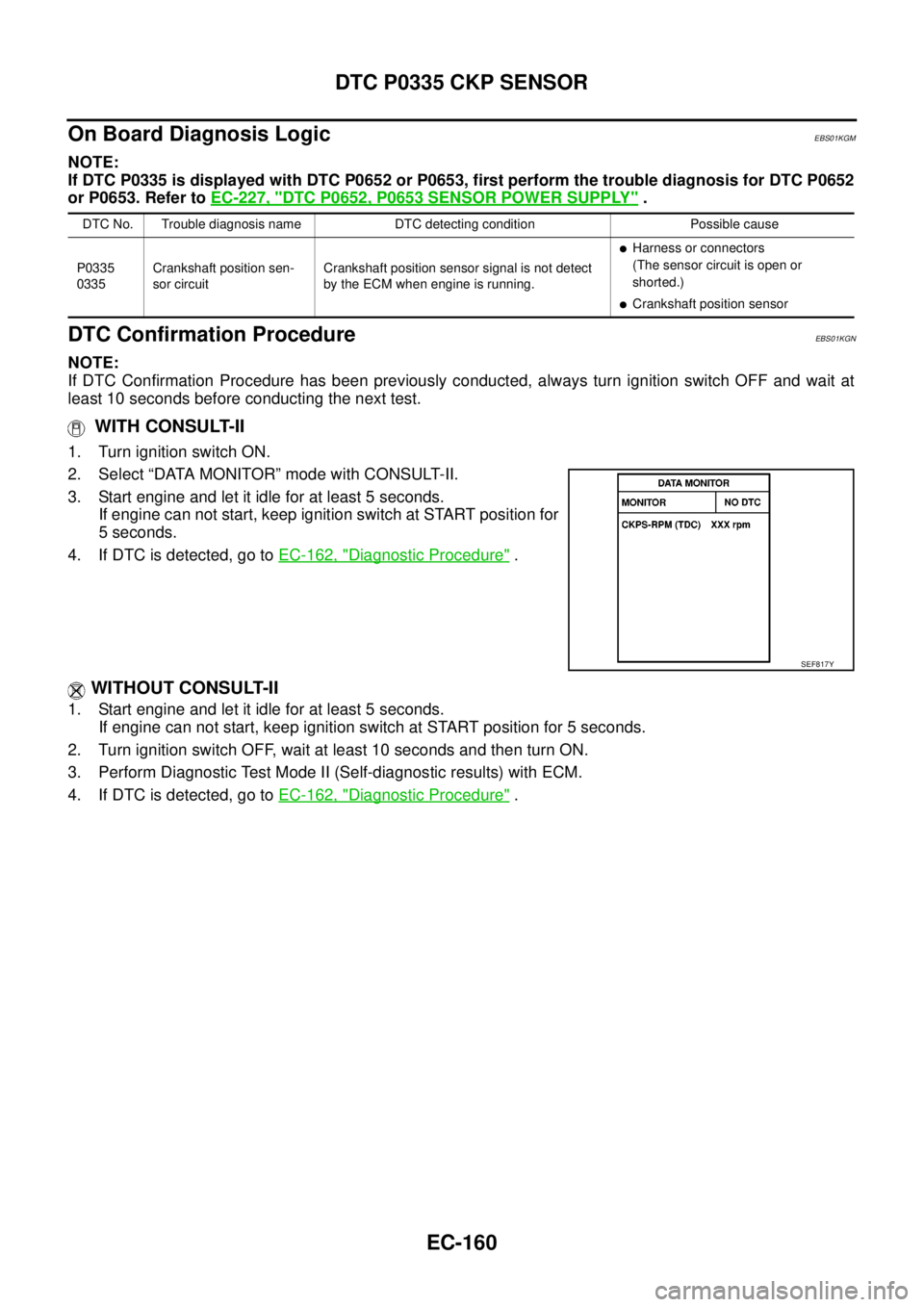
WITH CONSULT-II
1. Turn ignition switch ON.
2. Select “DATA MONITOR” mode with CONSULT-II.
3. Start engine and let it idle for at least 5 seconds.
If engine can not start, keep ignition switch at START position for
5 seconds.
4. If DTC is detected, go toEC-162, "
Diagnostic Procedure".
WITHOUT CONSULT-II
1. Start engine and let it idle for at least 5 seconds.
If engine can not start, keep ignition switch at START position for 5 seconds.
2. Turn ignition switch OFF, wait at least 10 seconds and then turn ON.
3. Perform Diagnostic Test Mode II (Self-diagnostic results) with ECM.
4. If DTC is detected, go toEC-162, "
Diagnostic Procedure".
DTC No. Trouble diagnosis name DTC detecting condition Possible cause
P0335
0335Crankshaft position sen-
sor circuitCrankshaft position sensor signal is not detect
by the ECM when engine is running.
lHarness or connectors
(The sensor circuit is open or
shorted.)
lCrankshaft position sensor
SEF817Y
Page 1141 of 3171
DTC P0335 CKP SENSOR
EC-161
C
D
E
F
G
H
I
J
K
L
MA
EC
Wiring DiagramEBS01KGO
MBWA1046E
Page 1142 of 3171
EC-162
DTC P0335 CKP SENSOR
Diagnostic Procedure
EBS01KGP
1.CHECK GROUND CONNECTIONS
1. Turn ignition switch OFF.
2. Loosen and retighten three ground screws on the body.
Refer toEC-78, "
Ground Inspection".
OK or NG
OK >> GO TO 2.
NG >> Repair or replace ground connections.
2.CHECK CKP SENSOR POWER SUPPLY CIRCUIT
1. Disconnect crankshaft position sensor (1) harness connector.
–Illustration shows the view from under the vehicle
–: Vehicle front
–Starter motor (2)
2. Turn ignition switch ON.
3. Check voltage between CKP sensor terminal 3 and ground with
CONSULT-II or tester.
OK or NG
OK >> GO TO 3.
NG >> Repair open circuit or short to ground or short to power
in harness or connectors.
: Vehicle front
1. Body ground E21 2. ECM 3. Body ground E41
4. A/C high-pressure service valve 5. ABS actuator and electric unit
(control unit)6. Body ground E61
MBIB1218E
MBIB1211E
Voltage: Approximately 5.3V
MBIB1293E
Page 1143 of 3171

DTC P0335 CKP SENSOR
EC-163
C
D
E
F
G
H
I
J
K
L
MA
EC
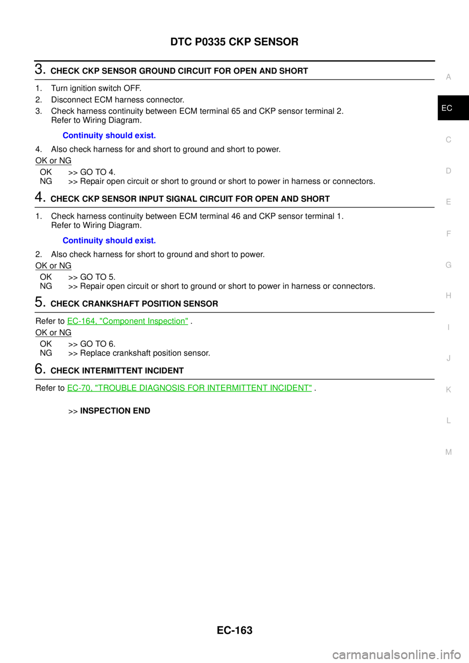
3.CHECK CKP SENSOR GROUND CIRCUIT FOR OPEN AND SHORT
1. Turn ignition switch OFF.
2. Disconnect ECM harness connector.
3. Check harness continuity between ECM terminal 65 and CKP sensor terminal 2.
Refer to Wiring Diagram.
4. Also check harness for and short to ground and short to power.
OK or NG
OK >> GO TO 4.
NG >> Repair open circuit or short to ground or short to power in harness or connectors.
4.CHECK CKP SENSOR INPUT SIGNAL CIRCUIT FOR OPEN AND SHORT
1. Check harness continuity between ECM terminal 46 and CKP sensor terminal 1.
Refer to Wiring Diagram.
2. Also check harness for short to ground and short to power.
OK or NG
OK >> GO TO 5.
NG >> Repair open circuit or short to ground or short to power in harness or connectors.
5.CHECK CRANKSHAFT POSITION SENSOR
Refer toEC-164, "
Component Inspection".
OK or NG
OK >> GO TO 6.
NG >> Replace crankshaft position sensor.
6.CHECK INTERMITTENT INCIDENT
Refer toEC-70, "
TROUBLE DIAGNOSIS FOR INTERMITTENT INCIDENT".
>>INSPECTION END Continuity should exist.
Continuity should exist.
Page 1144 of 3171
EC-164
DTC P0335 CKP SENSOR
Component Inspection
EBS01KGQ
CRANKSHAFT POSITION SENSOR
1. Loosen the fixing bolt of the sensor.
2. Disconnect crankshaft position sensor harness connector.
3. Remove the sensor.
4. Visually check the sensor for chipping.
5. Check resistance as shown in the figure.
6. If NG, replace crankshaft position sensor.
Removal and InstallationEBS01KGR
CRANKSHAFT POSITION SENSOR
Refer toEM-36, "OIL PAN AND OIL STRAINER".
MBIB0647E
Terminal No. (Polarity) ResistanceW[at 25°C(77°F)]
1(+)-2(-)
Except 0 or¥ 3(+)-1(-)
3(+)-2(-)
MBIB1385E
Page 1145 of 3171

DTC P0336 CKP SENSOR
EC-165
C
D
E
F
G
H
I
J
K
L
MA
EC
DTC P0336 CKP SENSORPFP:23731
DescriptionEBS01KGS
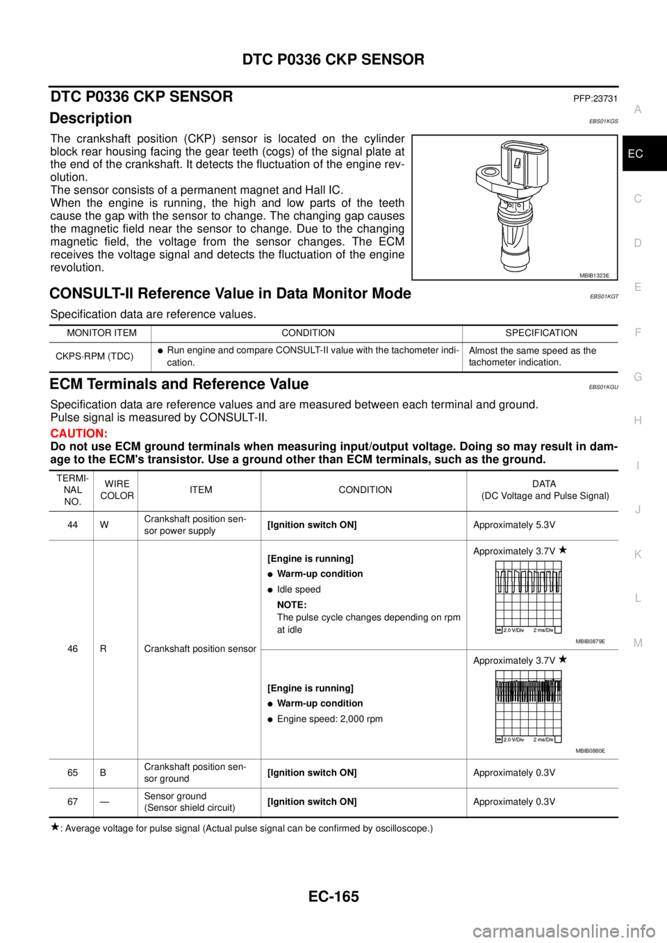
The crankshaft position (CKP) sensor is located on the cylinder
block rear housing facing the gear teeth (cogs) of the signal plate at
the end of the crankshaft. It detects the fluctuation of the engine rev-
olution.
The sensor consists of a permanent magnet and Hall IC.
When the engine is running, the high and low parts of the teeth
cause the gap with the sensor to change. The changing gap causes
the magnetic field near the sensor to change. Due to the changing
magnetic field, the voltage from the sensor changes. The ECM
receives the voltage signal and detects the fluctuation of the engine
revolution.
CONSULT-II Reference Value in Data Monitor ModeEBS01KGT
Specification data are reference values.
ECM Terminals and Reference ValueEBS01KGU
Specification data are reference values and are measured between each terminal and ground.
Pulse signal is measured by CONSULT-II.
CAUTION:
Do not use ECM ground terminals when measuring input/output voltage. Doing so may result in dam-
age to the ECM's transistor. Use a ground other than ECM terminals, such as the ground.
: Average voltage for pulse signal (Actual pulse signal can be confirmed by oscilloscope.)
MBIB1323E
MONITOR ITEM CONDITION SPECIFICATION
CKPS·RPM (TDC)
lRun engine and compare CONSULT-II value with the tachometer indi-
cation.Almost the same speed as the
tachometer indication.
TERMI-
NAL
NO.WIRE
COLORITEM CONDITIONDATA
(DC Voltage and Pulse Signal)
44 WCrankshaft position sen-
sor power supply[Ignition switch ON]Approximately 5.3V
46 R Crankshaft position sensor[Engine is running]
lWarm-up condition
lIdle speed
NOTE:
The pulse cycle changes depending on rpm
at idleApproximately 3.7V
[Engine is running]
lWarm-up condition
lEngine speed: 2,000 rpmApproximately 3.7V
65 BCrankshaft position sen-
sor ground[Ignition switch ON]Approximately 0.3V
67 —Sensor ground
(Sensor shield circuit)[Ignition switch ON]Approximately 0.3V
MBIB0879E
MBIB0880E