Page 1066 of 3171

EC-86
DTC P0089 FUEL PUMP
DTC P0089 FUEL PUMP
PFP:16700
On Board Diagnosis LogicEBS01KDM
The MI will not light up for this self-diagnosis.
NOTE:
If DTC P0089 is displayed with DTC P0652 or P0653, first perform the trouble diagnosis for DTC P0652
or P0653. Refer toEC-227, "
DTC P0652, P0653 SENSOR POWER SUPPLY".
DTC Confirmation ProcedureEBS01KDN
NOTE:
If DTC Confirmation Procedure has been previously conducted, always turn ignition switch OFF and wait at
least 10 seconds before conducting the next test.
WITH CONSULT-II
1. Start engine and warm it up to normal operating temperature.
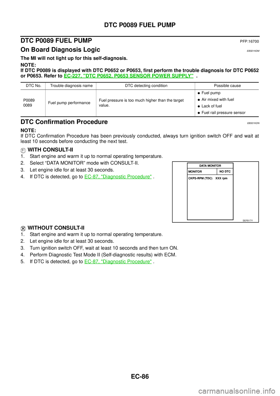
2. Select “DATA MONITOR” mode with CONSULT-II.
3. Let engine idle for at least 30 seconds.
4. If DTC is detected, go toEC-87, "
Diagnostic Procedure".
WITHOUT CONSULT-II
1. Start engine and warm it up to normal operating temperature.
2. Let engine idle for at least 30 seconds.
3. Turn ignition switch OFF, wait at least 10 seconds and then turn ON.
4. Perform Diagnostic Test Mode II (Self-diagnostic results) with ECM.
5. If DTC is detected, go toEC-87, "
Diagnostic Procedure".
DTC No. Trouble diagnosis name DTC detecting condition Possible cause
P0089
0089Fuel pump performanceFuel pressure is too much higher than the target
value.
lFuel pump
lAir mixed with fuel
lLack of fuel
lFuel rail pressure sensor
SEF817Y
Page 1067 of 3171

DTC P0089 FUEL PUMP
EC-87
C
D
E
F
G
H
I
J
K
L
MA
EC
Diagnostic ProcedureEBS01KDO
1.PERFORM FUEL PUMP LEARNING VALUE CLEARING
NOTE:
If the DTC is detected because of air mixed with fuel (i.e.: caused by lack of fuel), it may become normal by
performing following procedure.
With CONSULT-II
1. Turn ignition switch ON.
2. Perform Fuel Pump Learning Value Clearing. Refer toEC-24, "
Fuel Pump Learning Value Clearing".
3. Start engine and let it idle for at least 60 seconds.
4. Select “SELF-DIAG RESULT” mode with CONSULT-II.
5. Touch “ERASE”.
6. PerformEC-86, "
DTC Confirmation Procedure",again.
7. Is DTC detected again?
Without CONSULT-II
1. Turn ignition switch ON.
2. Perform Fuel Pump Learning Value Clearing. Refer toEC-24, "
Fuel Pump Learning Value Clearing".
3. Start engine and let it idle for at least 60 seconds.
4. Erase the Diagnostic Test Mode II (Self-diagnostic results) memory. Refer toEC-27
.
5. PerformEC-86, "
DTC Confirmation Procedure",again.
6. Is DTC detected again?
Ye s o r N o
Ye s > > G O T O 2 .
No >>INSPECTION END
2.CHECK FUEL RAIL PRESSURE SENSOR
Refer toEC-122, "
Component Inspection".
OK or NG
OK >> GO TO 3.
NG >> Replace fuel rail.
3.CHECK FUEL PUMP
Refer toEC-221, "
Component Inspection".
OK or NG
OK >> GO TO 5.
NG >> GO TO 4.
4.REPLACE FUEL PUMP
1. Replace Fuel pump.
2. Perform Fuel Pump Learning Value Clearing. Refer toEC-24, "
Fuel Pump Learning Value Clearing".
>>INSPECTION END
5.CHECK INTERMITTENT INCIDENT
Refer toEC-70, "
TROUBLE DIAGNOSIS FOR INTERMITTENT INCIDENT".
>>INSPECTION END
Removal and InstallationEBS01KDP
FUEL PUMP
Refer toEM-49, "FUEL PUMP".
Page 1068 of 3171

EC-88
DTC P0093 FUEL SYSTEM
DTC P0093 FUEL SYSTEM
PFP:17520
On Board Diagnosis LogicEBS01KDQ
NOTE:
If DTC P0093 is displayed with DTC P0652 or P0653, first perform the trouble diagnosis for DTC P0652
or P0653. Refer toEC-227, "
DTC P0652, P0653 SENSOR POWER SUPPLY".
DTC Confirmation ProcedureEBS01KDR
NOTE:
If DTC Confirmation Procedure has been previously conducted, always turn ignition switch OFF and wait at
least 10 seconds before conducting the next test.
WITH CONSULT-II
1. Turn ignition switch ON.
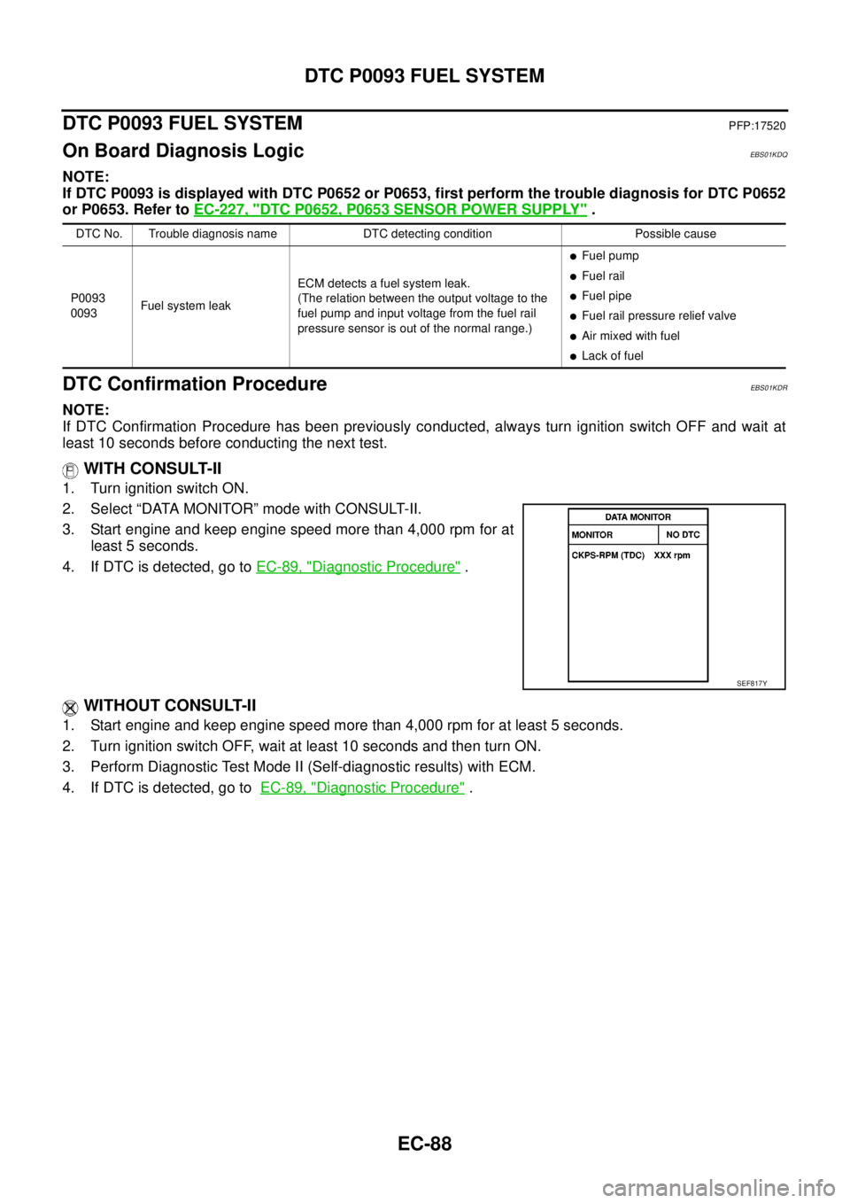
2. Select “DATA MONITOR” mode with CONSULT-II.
3. Start engine and keep engine speed more than 4,000 rpm for at
least 5 seconds.
4. If DTC is detected, go toEC-89, "
Diagnostic Procedure".
WITHOUT CONSULT-II
1. Start engine and keep engine speed more than 4,000 rpm for at least 5 seconds.
2. Turn ignition switch OFF, wait at least 10 seconds and then turn ON.
3. Perform Diagnostic Test Mode II (Self-diagnostic results) with ECM.
4. If DTC is detected, go toEC-89, "
Diagnostic Procedure".
DTC No. Trouble diagnosis name DTC detecting condition Possible cause
P0093
0093Fuel system leakECM detects a fuel system leak.
(The relation between the output voltage to the
fuel pump and input voltage from the fuel rail
pressure sensor is out of the normal range.)
lFuel pump
lFuel rail
lFuel pipe
lFuel rail pressure relief valve
lAir mixed with fuel
lLack of fuel
SEF817Y
Page 1072 of 3171

EC-92
DTC P0102, P0103 MAF SENSOR
DTC P0102, P0103 MAF SENSOR
PFP:22680
Component DescriptionEBS01KDV
The mass air flow sensor (1) is placed in the stream of intake air. It
measures the intake flow rate by measuring a part of the entire
intake flow. The mass air flow sensor controls the temperature of the
hot wire to a certain amount. The heat generated by the hot wire is
reduced as the intake air flows around it. The more air, the greater
the heat loss.
Therefore, the electric current supplied to hot wire is changed to
maintain the temperature of the hot wire as air flow increases. The
ECM detects the air flow by means of this current change.
CONSULT-II Reference Value in Data Monitor ModeEBS01KDW
Specification data are reference values.
*: This signal is converted by ECM internally. Thus, it differs from ECM terminal voltage.
ECM Terminals and Reference ValueEBS01KDX
Specification data are reference values, and are measured between each terminal and ground.
CAUTION:
Do not use ECM ground terminals when measuring input/output voltage. Doing so may result in dam-
age to the ECM's transistor. Use a ground other than ECM terminals, such as the ground.
PBIA9559J
MONITOR ITEM CONDITION SPECIFICATION
MAS AIR/FL SE*
lEngine: After warming up
lAir conditioner switch: OFF
lShift lever: P or N (A/T), Neutral (M/T)
lNo loadIgnition switch: ON
(Engine stopped)Approximately 0.4V
Idle 1.3 - 1.7V
Engine is revving from idle to
about 4,000 rpm.1.3 - 1.7V to Approximately 4.0V
(Check for liner voltage rise in
response to engine being
increased to about 4,000 rpm)
TERMI-
NAL
NO.WIRE
COLORITEM CONDITIONDATA
(DC Voltage)
54 G Mass air flow sensor[Ignition switch: ON]Approximately 0.7V
[Engine is running]
lWarm-up condition
lIdle speed1.6 - 2.0V
[Engine is running]
lWarm-up condition
lEngine is revving from idle to about 4,000 rpm.1.6 - 2.0V to Approximately 4.3V
(Check for liner voltage rise in
response to engine being
increased to about 4,000 rpm)
67 —Sensor ground
(Sensor shield circuit)[Engine is running]
lWarm-up condition
lIdle speedApproximately 0.3V
73 BMass air flow sensor
ground[Ignition switch ON]Approximately 0.3V
Page 1073 of 3171

DTC P0102, P0103 MAF SENSOR
EC-93
C
D
E
F
G
H
I
J
K
L
MA
EC
On Board Diagnosis LogicEBS01KDY
The MI will not light up for these self-diagnoses.
DTC Confirmation ProcedureEBS01KDZ
NOTE:
If DTC Confirmation Procedure has been previously conducted, always turn ignition switch OFF and wait at
least 10 seconds before conducting the next test.
WITH CONSULT-II
1. Turn ignition switch ON.
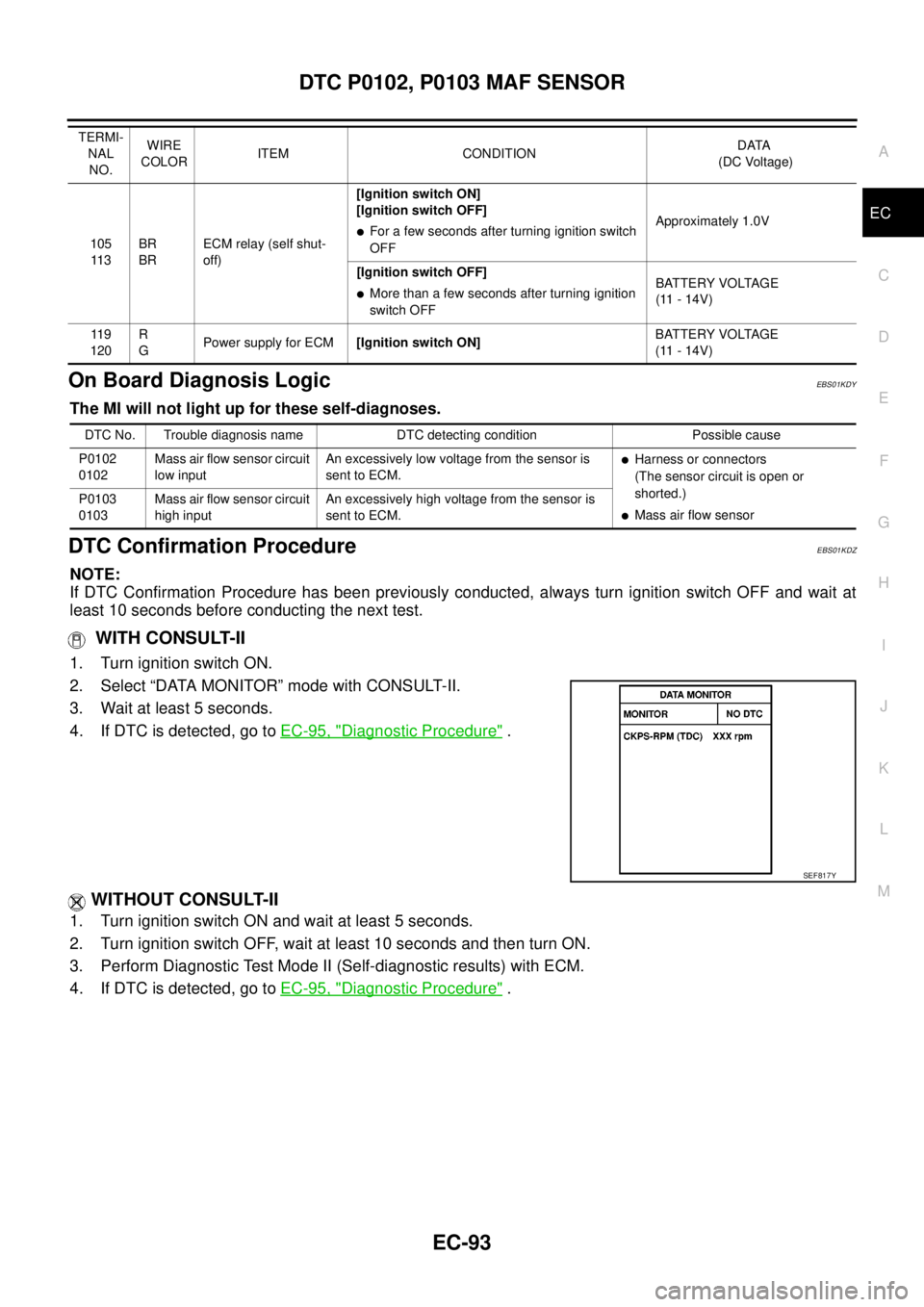
2. Select “DATA MONITOR” mode with CONSULT-II.
3. Wait at least 5 seconds.
4. If DTC is detected, go toEC-95, "
Diagnostic Procedure".
WITHOUT CONSULT-II
1. Turn ignition switch ON and wait at least 5 seconds.
2. Turn ignition switch OFF, wait at least 10 seconds and then turn ON.
3. Perform Diagnostic Test Mode II (Self-diagnostic results) with ECM.
4. If DTC is detected, go toEC-95, "
Diagnostic Procedure".
105
11 3BR
BRECM relay (self shut-
off)[Ignition switch ON]
[Ignition switch OFF]lFor a few seconds after turning ignition switch
OFFApproximately 1.0V
[Ignition switch OFF]
lMore than a few seconds after turning ignition
switch OFFBATTERY VOLTAGE
(11 - 14V)
11 9
120R
GPower supply for ECM[Ignition switch ON]BATTERY VOLTAGE
(11 - 14V) TERMI-
NAL
NO.WIRE
COLORITEM CONDITIONDATA
(DC Voltage)
DTC No. Trouble diagnosis name DTC detecting condition Possible cause
P0102
0102Mass air flow sensor circuit
low inputAn excessively low voltage from the sensor is
sent to ECM.
lHarness or connectors
(The sensor circuit is open or
shorted.)
lMass air flow sensor P0103
0103Mass air flow sensor circuit
high inputAn excessively high voltage from the sensor is
sent to ECM.
SEF817Y
Page 1074 of 3171
EC-94
DTC P0102, P0103 MAF SENSOR
Wiring Diagram
EBS01KE0
MBWA1036E
Page 1075 of 3171
DTC P0102, P0103 MAF SENSOR
EC-95
C
D
E
F
G
H
I
J
K
L
MA
EC
Diagnostic ProcedureEBS01KE1
1.CHECK GROUND CONNECTIONS
1. Turn ignition switch OFF.
2. Loosen and retighten three ground screws on the body.
Refer toEC-78, "
Ground Inspection".
OK or NG
OK >> GO TO 2.
NG >> Repair or replace ground connections.
2.CHECK MAFS POWER SUPPLY CIRCUIT
1. Disconnect mass air flow (MAF) sensor (1) harness connector.
–: Vehicle front
2. Turn ignition switch ON.
3. Check voltage between MAF sensor terminal 5 and ground with
CONSULT-II or tester.
OK or NG
OK >> GO TO 4.
NG >> GO TO 3.
: Vehicle front
1. Body ground E21 2. ECM 3. Body ground E41
4. A/C high-pressure service valve 5. ABS actuator and electric unit
(control unit)6. Body ground E61
MBIB1218E
MBIB1200E
Voltage: Battery voltage
PBIB1597E
Page 1076 of 3171

EC-96
DTC P0102, P0103 MAF SENSOR
3.DETECT MALFUNCTIONING PART
Check the following.
lHarness connectors E9, F4
lHarness for open or short between IPDM E/R and mass air flow sensor
lHarness for open or short between ECM and mass air flow sensor
>> Repair open circuit or short to ground or short to power in harness or connectors.
4.CHECK MAFS GROUND CIRCUIT FOR OPEN AND SHORT
1. Turn ignition switch OFF.
2. Disconnect ECM harness connector.
3. Check harness continuity between MAF sensor terminal 4 and ECM terminal 73.
Refer to Wiring Diagram.
4. Also check harness for short to ground and short to power.
OK or NG
OK >> GO TO 5.
NG >> Repair open circuit or short to ground or short to power in harness or connectors.
5.CHECK MAFS INPUT SIGNAL CIRCUIT FOR OPEN AND SHORT
1. Check harness continuity between MAF sensor terminal 3 and ECM terminal 54.
Refer to Wiring Diagram.
2. Also check harness for short to ground and short to power.
OK or NG
OK >> GO TO 6.
NG >> Repair open circuit or short to ground or short to power in harness or connectors.
6.CHECK MASS AIR FLOW SENSOR
Refer toEC-96, "
Component Inspection".
OK or NG
OK >> GO TO 7.
NG >> Replace mass air flow sensor.
7.CHECK INTERMITTENT INCIDENT
Refer toEC-70, "
TROUBLE DIAGNOSIS FOR INTERMITTENT INCIDENT".
>>INSPECTION END
Component InspectionEBS01KE2
MASS AIR FLOW SENSOR
With CONSULT-II
1. Reconnect all harness connectors disconnected.
2. Start engine and warm it up to normal operating temperature.
3. Connect CONSULT-II and select “DATA MONITOR” mode.Continuity should exist.
Continuity should exist.