2005 NISSAN NAVARA sensor
[x] Cancel search: sensorPage 1040 of 3171

EC-60
TROUBLE DIAGNOSIS
ENGINE CONTROL COMPONENT PARTS/CONTROL SYSTEMS APPLICATION
X: ApplicableItemDIAGNOSTIC TEST MODE
SELF-DIAG RESULTS
DATA MON-
ITORACTIVE
TEST
DTCFREEZE
FRAME
DATA
ENGINE CONTROL COMPONENT PARTS
INPUTCrankshaft position sensor´´´
Camshaft position sensor´
Engine coolant temperature sensor´´´´
Vehicle speed signal´´´
Fuel pump temperature sensor´´
Accelerator pedal position sensor 1´´
Accelerator pedal position sensor 2´´
Fuel rail pressure sensor´´
Mass air flow sensor´´
Intake air temperature sensor´
Turbocharger boost sensor´´´
Refrigerant pressure sensor´
Battery voltage´´
Park/neutral position (PNP) switch´
Heat up switch´
Stop lamp switch´´
Barometric pressure sensor (built-into ECM)´´
ASCD steering switch´´
ASCD brake switch´´
ASCD clutch switch´´
OUTPUTFuel pump´´´
Fuel injector´´´
Glow relay´´
Cooling fan relay´´´
Turbocharger boost control solenoid valve´
Intake air control valve control solenoid valve
EGR volume control valve´´
Page 1042 of 3171

EC-62
TROUBLE DIAGNOSIS
WORK SUPPORT MODE
Work Item
SELF-DIAGNOSTIC MODE
Self Diagnostic Item
Regarding items detected in “SELF-DIAG RESULTS” mode, refer to —EC-6, "INDEX FOR DTC".
Freeze Frame Data
DATA MONITOR MODE
WORK ITEM DESCRIPTION USAGE
ENTER INJCTR CALIB DATA
lInjector adjustment value is written onto ECM memory. When performing Injector Adjust-
ment Value Registration.
CONFIG CLR
lASCD application status stored in ECM is initialized.
NOTE:
After the status is initialized, ECM recognizes ASCD
application status when the following condition is met.
lFor ASCD: ASCD MAIN switch is pressed.When initializing ASCD applica-
tion status stored in ECM.
INJ ADJ VAL CLR
lInjector adjustment value stored in ECM is initialized. Before changing injector adjust-
ment value stored in ECM, it is
recommended to perform this
work item.
Freeze frame data item Description
DIAG TROUBLE CODE
[PXXXX]
lThe engine control component part/control system has a trouble code, it is displayed as “PXXXX”.
(Refer toEC-6, "
INDEX FOR DTC".)
CAL/LD VALUE [%]
lThe calculated load value at the moment a malfunction is detected is displayed.
COOLANT TEMP [°C] or [°F]
lThe engine coolant temperature at the moment a malfunction is detected is displayed.
ENGINE SPEED [rpm]
lThe engine speed at the moment a malfunction is detected is displayed.
VEHICL SPEED
[km/h] or [mph]
lThe vehicle speed at the moment a malfunction is detected is displayed.
INT MANI PRES [kPa]
lThe intake manifold pressure at the moment a malfunction is detected is displayed.
MONITOR ITEMECM
INPUT
SIG-
NALMAIN
SIG-
NALSCONDITION SPECIFICATION
CKPS·RPM (TDC) [rpm]´´
lThe engine speed computed from the
crankshaft position sensor signal is
displayed.
COOLAN TEMP/S
[°C] or [°F]´´
lThe engine coolant temperature
(determined by the signal voltage of
the engine coolant temperature sen-
sor) is displayed.When the engine coolant temperature
circuit is open or short, ECM enters fail-
safe mode. The engine coolant tempera-
ture determined by the ECM is dis-
played.
VHCL SPEED SE
[km/h] or [mph]´´
lThe vehicle speed computed form the
vehicle speed signal is displayed.
FUEL TEMP SEN
[°C] or [°F]´´
lThe fuel temperature (determined by
the signal voltage of the fuel pump
temperature sensor) is displayed.
ACCEL POS SEN [V]´´
lThe accelerator pedal position sensor
1 signal voltage is displayed.This signal is converted by ECM inter-
nally. Thus, these differ from ECM termi-
nals voltage.
ACCEL SEN 2 [V]´´
lThe accelerator pedal position sensor
2 signal voltage is displayed.This signal is converted by ECM inter-
nally. Thus, these differ from ECM termi-
nals voltage.
Page 1043 of 3171
![NISSAN NAVARA 2005 Repair Workshop Manual TROUBLE DIAGNOSIS
EC-63
C
D
E
F
G
H
I
J
K
L
MA
ECACT CR PRESS [MPa]´´
lThe Fuel rail pressure (determined by
the signal voltage of the fuel rail pres-
sure sensor) is displayed.
BATTERY VOLT [V]´´ NISSAN NAVARA 2005 Repair Workshop Manual TROUBLE DIAGNOSIS
EC-63
C
D
E
F
G
H
I
J
K
L
MA
ECACT CR PRESS [MPa]´´
lThe Fuel rail pressure (determined by
the signal voltage of the fuel rail pres-
sure sensor) is displayed.
BATTERY VOLT [V]´´](/manual-img/5/57362/w960_57362-1042.png)
TROUBLE DIAGNOSIS
EC-63
C
D
E
F
G
H
I
J
K
L
MA
ECACT CR PRESS [MPa]´´
lThe Fuel rail pressure (determined by
the signal voltage of the fuel rail pres-
sure sensor) is displayed.
BATTERY VOLT [V]´´
lThe power supply voltage of ECM is
displayed.
P/N POSI SW [ON/OFF]´´
lIndicates [ON/OFF] condition from the
park/neutral position switch signal.
START SIGNAL [ON/OFF]´´
lIndicates [ON/OFF] condition from the
starter signal.
AIR COND SIG [ON/OFF]´´
lIndicates [ON/OFF] condition of the air
conditioner switch as determined by
the air conditioner signal.
BRAKE SW [ON/OFF]´´
lIndicates [ON/OFF] condition from the
stop lamp switch signal.
BRAKE SW2 [ON/OFF]´´
lIndicates [ON/OFF] condition from the
ASCD brake switch and ASCD clutch
switch signal.
IGN SW [ON/OFF]´´
lIndicates [ON/OFF] condition from
ignition switch signal.
WARM UP SW [ON/OFF]´
lIndicates [ON/OFF] condition from
heat up switch signal.
MAS AIR/FL SE [V]´´
lThe signal voltage of the mass air flow
sensor is displayed.This signal is converted by ECM inter-
nally. Thus, these differ from ECM termi-
nals voltage.
MAIN INJ WID [msec]´
lIndicates the actual fuel injection pulse
width compensated by ECM according
to the input signals.
PUMP CURRENT [mA]´
lIndicates the fuel pump power supply
current from the ECM.
GLOW RLY [ON/OFF]´
lThe glow relay control condition
(determined by ECM according to the
input signal) is displayed.
COOLING FAN
[LOW/HI/OFF]´
lIndicates the control condition of the
cooling fans (determined by ECM
according to the input signal).
LOW ... Operates at low speed
HI ... Operates at high speed
OFF ... Stopped
EGR VOL CON/V [step]´
lIndicates the EGR volume control
value computed by the ECM accord-
ing to the input signals.
lThe opening becomes larger as the
value increases.
INT/A VOLUME [mg/]
lThe intake air volume computed from
the mass air flow sensor signal is dis-
played.
BARO SEN [kPa]´´
lThe barometric pressure (determined
by the signal voltage from the absolute
pressure sensor built into the ECM) is
displayed. MONITOR ITEMECM
INPUT
SIG-
NALMAIN
SIG-
NALSCONDITION SPECIFICATION
Page 1044 of 3171
![NISSAN NAVARA 2005 Repair Workshop Manual EC-64
TROUBLE DIAGNOSIS
NOTE:
Any monitored item that does not match the vehicle being diagnosed is deleted from the display automatically.
ACTIVE TEST MODE
INT/M PRES SE [kPa]
lTurbocharger boost (de NISSAN NAVARA 2005 Repair Workshop Manual EC-64
TROUBLE DIAGNOSIS
NOTE:
Any monitored item that does not match the vehicle being diagnosed is deleted from the display automatically.
ACTIVE TEST MODE
INT/M PRES SE [kPa]
lTurbocharger boost (de](/manual-img/5/57362/w960_57362-1043.png)
EC-64
TROUBLE DIAGNOSIS
NOTE:
Any monitored item that does not match the vehicle being diagnosed is deleted from the display automatically.
ACTIVE TEST MODE
INT/M PRES SE [kPa]
lTurbocharger boost (determined by
the signal voltage from the turbo-
charger boost sensor) is displayed.
CYL COUNT [1/2/3/4]
lThe cylinder being injected is dis-
played.
1 ... Cylinder No.1 is injected.
2 ... Cylinder No.2 is injected.
3 ... Cylinder No.3 is injected.
4 ... Cylinder No.4 is injected.
SET SW
[ON/OFF]´
lIndicates [ON/OFF] condition from
SET/COAST switch signal.
RESUME/ACC SW
[ON/OFF]´
lIndicates [ON/OFF] condition from
RESUME/ACCEL switch signal.
CANCEL SW
[ON/OFF]´
lIndicates [ON/OFF] condition from
CANCEL switch signal.
MAIN SW
[ON/OFF]´
lIndicates [ON/OFF] condition from
MAIN switch signal.
ASCD APPLY [YES/NO]
lDisplaying ASCD application status
stored in ECM.
VDC APPLY [YES/NO]
lDisplaying ESP application status
stored in ECM.
AC PRESS SEN [V]
lThe signal voltage from the refrigerant
pressure sensor is displayed.
Voltage [V]
Voltage, frequency, duty cycle or pulse
width measured by the probe.Only “#” is displayed if item is unable to
be measured.
Figures with “#”s are temporary ones.
They are the same figures as an actual
piece of data which was just previously
measured. [Hz] or [%] Frequency
[msec],[Hz]or[%]
DUTY-HI
DUTY-LOW
PLS WIDTH-HI
PLS WIDTH-LOWMONITOR ITEMECM
INPUT
SIG-
NALMAIN
SIG-
NALSCONDITION SPECIFICATION
TEST ITEM CONDITION JUDGEMENT CHECK ITEM (REMEDY)
POWER BAL-
ANCE
lEngine: After warming up, idle the
engine.
lA/C switch: OFF
lShift lever: P or N (A/T), Neutral
(M/T)
lCut off each injector signal one at
a time using CONSULT-IIEngine runs rough or dies.
lHarness and connectors
lCompression
lFuel injector
COOLING FAN *
lIgnition switch: ON
lOperate the cooling fan at LOW,
HI speed and turn OFF using
CONSULT-II.Cooling fan moves at LOW, HI
speed and stops.lHarness and connector
lCooling fan motor
lCooling fan relay
ENG COOLANT
TEMP
lEngine: Return to the original
trouble condition
lChange the engine coolant tem-
perature using CONSULT-II.If trouble symptom disappears, see
CHECK ITEM.
lHarness and connectors
lEngine coolant temperature sen-
sor
lFuel injector
Page 1049 of 3171

TROUBLE DIAGNOSIS
EC-69
C
D
E
F
G
H
I
J
K
L
MA
EC
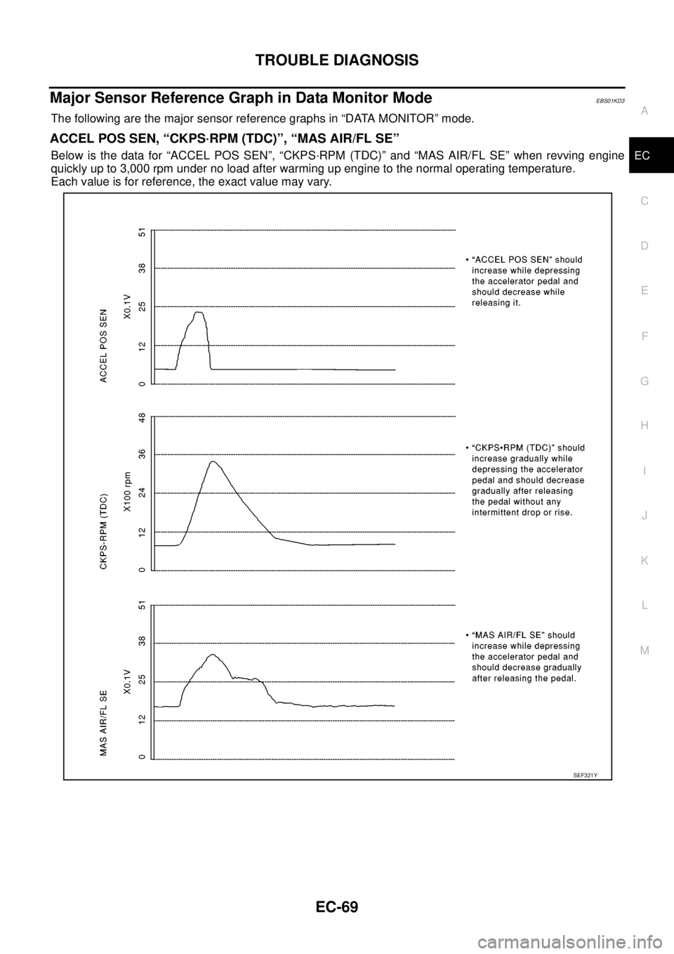
Major Sensor Reference Graph in Data Monitor ModeEBS01KD3
The following are the major sensor reference graphs in “DATA MONITOR” mode.
ACCEL POS SEN, “CKPS·RPM (TDC)”, “MAS AIR/FL SE”
Below is the data for “ACCEL POS SEN”, “CKPS·RPM (TDC)” and “MAS AIR/FL SE” when revving engine
quickly up to 3,000 rpm under no load after warming up engine to the normal operating temperature.
Each value is for reference, the exact value may vary.
SEF321Y
Page 1062 of 3171

EC-82
DTC P0016 CKP - CMP CORRELATION
DTC P0016 CKP - CMP CORRELATION
PFP:10328
On Board Diagnosis LogicEBS01KDF
The MI will not light up for this self-diagnosis.
NOTE:
If DTC P0016 is displayed with DTC P0652 or P0653, first perform the trouble diagnosis for DTC P0652
or P0653. Refer toEC-227, "
DTC P0652, P0653 SENSOR POWER SUPPLY".
DTC Confirmation ProcedureEBS01KDG
NOTE:
If DTC Confirmation Procedure has been previously conducted, always turn ignition switch OFF and wait at
least 10 seconds before conducting the next test.
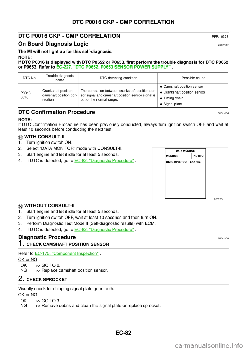
WITH CONSULT-II
1. Turn ignition switch ON.
2. Select “DATA MONITOR” mode with CONSULT-II.
3. Start engine and let it idle for at least 5 seconds.
4. If DTC is detected, go toEC-82, "
Diagnostic Procedure".
WITHOUT CONSULT-II
1. Start engine and let it idle for at least 5 seconds.
2. Turn ignition switch OFF, wait at least 10 seconds and then turn ON.
3. Perform Diagnostic Test Mode II (Self-diagnostic results) with ECM.
4. If DTC is detected, go toEC-82, "
Diagnostic Procedure".
Diagnostic ProcedureEBS01KDH
1.CHECK CAMSHAFT POSITION SENSOR
Refer toEC-175, "
Component Inspection".
OK or NG
OK >> GO TO 2.
NG >> Replace camshaft position sensor.
2.CHECK SPROCKET
Visually check for chipping signal plate gear tooth.
OK or NG
OK >> GO TO 3.
NG >> Remove debris and clean the signal plate or replace sprocket.
DTC No.Trouble diagnosis
nameDTC detecting condition Possible cause
P0016
0016Crankshaft position -
camshaft position cor-
relationThe correlation between crankshaft position sen-
sor signal and camshaft position sensor signal is
out of the normal range.
lCamshaft position sensor
lCrankshaft position sensor
lTiming chain
lSignal plate
SEF817Y
Page 1063 of 3171

DTC P0016 CKP - CMP CORRELATION
EC-83
C
D
E
F
G
H
I
J
K
L
MA
EC
3.CHECK CRANKSHAFT POSITION SENSOR
Refer toEC-164, "
Component Inspection".
OK or NG
OK >> GO TO 4.
NG >> Replace crankshaft position sensor.
4.CHECK GEAR TOOTH
Visually check for chipping signal plate gear tooth.
OK or NG
OK >> GO TO 5.
NG >> Replace the signal plate.
5.CHECK TIMING CHAIN
Refer toEM-73, "
SECONDARY TIMING CHAIN"andEM-79, "PRIMARY TIMING CHAIN".
OK or NG
OK >> GO TO 6.
NG >> Replace timing chain.
6.CHECK INTERMITTENT INCIDENT
Refer toEC-70, "
TROUBLE DIAGNOSIS FOR INTERMITTENT INCIDENT".
>>INSPECTION END
Page 1064 of 3171

EC-84
DTC P0088 FUEL SYSTEM
DTC P0088 FUEL SYSTEM
PFP:17520
On Board Diagnosis LogicEBS01KDI
NOTE:
If DTC P0088 is displayed with DTC P0652 or P0653, first perform the trouble diagnosis for DTC P0652
or P0653. Refer toEC-227, "
DTC P0652, P0653 SENSOR POWER SUPPLY".
DTC Confirmation ProcedureEBS01KDJ
NOTE:
If DTC Confirmation Procedure has been previously conducted, always turn ignition switch OFF and wait at
least 10 seconds before conducting the next test.
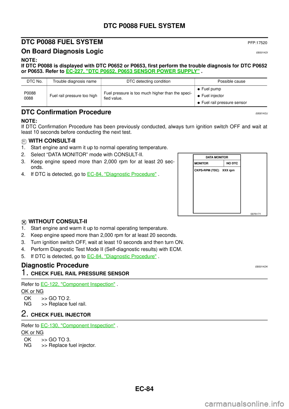
WITH CONSULT-II
1. Start engine and warm it up to normal operating temperature.
2. Select “DATA MONITOR” mode with CONSULT-II.
3. Keep engine speed more than 2,000 rpm for at least 20 sec-
onds.
4. If DTC is detected, go toEC-84, "
Diagnostic Procedure".
WITHOUT CONSULT-II
1. Start engine and warm it up to normal operating temperature.
2. Keep engine speed more than 2,000 rpm for at least 20 seconds.
3. Turn ignition switch OFF, wait at least 10 seconds and then turn ON.
4. Perform Diagnostic Test Mode II (Self-diagnostic results) with ECM.
5. If DTC is detected, go toEC-84, "
Diagnostic Procedure".
Diagnostic ProcedureEBS01KDK
1.CHECK FUEL RAIL PRESSURE SENSOR
Refer toEC-122, "
Component Inspection".
OK or NG
OK >> GO TO 2.
NG >> Replace fuel rail.
2.CHECK FUEL INJECTOR
Refer toEC-130, "
Component Inspection".
OK or NG
OK >> GO TO 3.
NG >> Replace fuel injector.
DTC No. Trouble diagnosis name DTC detecting condition Possible cause
P0088
0088Fuel rail pressure too highFuel pressure is too much higher than the speci-
fied value.
lFuel pump
lFuel injector
lFuel rail pressure sensor
SEF817Y