2005 NISSAN NAVARA warning light
[x] Cancel search: warning lightPage 1810 of 3171
![NISSAN NAVARA 2005 Repair Workshop Manual CAN COMMUNICATION
LAN-33
[CAN]
C
D
E
F
G
H
I
J
L
MA
B
LAN
Input/output signal chart
T: Transmit R: Receive
Signals ECMNAVI con-
trol unitFront air
controlBCMCombina-
tion meterABS actua-
tor and
elect NISSAN NAVARA 2005 Repair Workshop Manual CAN COMMUNICATION
LAN-33
[CAN]
C
D
E
F
G
H
I
J
L
MA
B
LAN
Input/output signal chart
T: Transmit R: Receive
Signals ECMNAVI con-
trol unitFront air
controlBCMCombina-
tion meterABS actua-
tor and
elect](/manual-img/5/57362/w960_57362-1809.png)
CAN COMMUNICATION
LAN-33
[CAN]
C
D
E
F
G
H
I
J
L
MA
B
LAN
Input/output signal chart
T: Transmit R: Receive
Signals ECMNAVI con-
trol unitFront air
controlBCMCombina-
tion meterABS actua-
tor and
electric unit
(control
unit)IPDM E/R
A/C compressor request signal TR
ASCD CRUISE lamp signal T R
ASCD SET lamp signal T R
Cooling fan speed request signal TR
Engine coolant temperature signal T R R
Engine speed signal T R R
Engine status signal T R R
Fuel consumption monitor signalTR
RT
Glow indicator signal T R
Glow relay signal T R
Malfunction indicator signal T R
A/C switch/indicator signal T
R
*
PTC heater signal R T
A/C switch signal R
R
*T
Buzzer output signal T R
Day time running light request signal R T R R
Door switch signal T R R
Front fog light request signal R T R R
Front wiper request signal T R
High beam request signal T R R
Horn chirp signal T R
Low beam request signal T R
Position light request signal T R R
Rear fog light request signal R T R
Rear window defogger switch signal
R
*TR
Sleep wake up signal T R R
Theft warning horn request signal T R
Trailer lamp signal T R
Turn indicator signal T R
Distance to empty signal R T
Fuel level low warning signal R T
ABS warning lamp signalRT
Vehicle speed signalR
*RT
RR
R
*RT
Front wiper stop position signal R T
Hood switch signal R T
Oil pressure switch signalRT
Rear window defogger control signal R T
Page 1812 of 3171
![NISSAN NAVARA 2005 Repair Workshop Manual CAN COMMUNICATION
LAN-35
[CAN]
C
D
E
F
G
H
I
J
L
MA
B
LAN
Closed throttle position signal T R
Cooling fan speed request signal TR
Engine coolant temperature signal T R R
Engine speed signal T R R R
En NISSAN NAVARA 2005 Repair Workshop Manual CAN COMMUNICATION
LAN-35
[CAN]
C
D
E
F
G
H
I
J
L
MA
B
LAN
Closed throttle position signal T R
Cooling fan speed request signal TR
Engine coolant temperature signal T R R
Engine speed signal T R R R
En](/manual-img/5/57362/w960_57362-1811.png)
CAN COMMUNICATION
LAN-35
[CAN]
C
D
E
F
G
H
I
J
L
MA
B
LAN
Closed throttle position signal T R
Cooling fan speed request signal TR
Engine coolant temperature signal T R R
Engine speed signal T R R R
Engine status signal T R R
Fuel consumption monitor signalTR
RT
Glow indicator signal T R
Glow relay signal T R
Malfunction indicator signal T R
Wide open throttle position signal T R
A/T fluid temperature sensor signal T R
A/T position indicator lamp signal T R
OD OFF indicator lamp signal T R
Output shaft revolution signal R T
Turbine revolution signal R T
A/C switch/indicator signal T R
PTC heater signal R T
A/C switch signal R R T
Buzzer output signal T R
Day time running light request signal R T R R
Door switch signalTR R
Front fog light request signal R T R R
Front wiper request signal T R
High beam request signal T R R
Horn chirp signalTR
Low beam request signal T R
Position light request signal T R R
Rear fog light request signal R T R
Rear window defogger switch signal R T R
Sleep wake up signal T R R
Theft warning horn request signal T R
Trailer lamp signalTR
Turn indicator signal T R
1st position switch signal R T
Distance to empty signal R T
Fuel level low warning signal R T
Overdrive control switch signal R T
Stop lamp switch signal R T
ABS operation signal R T
ABS warning lamp signalRT Signals ECM TCMNAVI
control
unitFront air
controlBCMCombi-
nation
meterABS
actuator
and elec-
tric unit
(control
unit)IPDM
E/R
Page 1816 of 3171
![NISSAN NAVARA 2005 Repair Workshop Manual CAN COMMUNICATION
LAN-39
[CAN]
C
D
E
F
G
H
I
J
L
MA
B
LAN
Input/output signal chart
T: Transmit R: Receive
Signals ECMNAVI
control
unitDiffer-
ential
lock
control
unitFront air
con-
trol
*1BCMCombi-
n NISSAN NAVARA 2005 Repair Workshop Manual CAN COMMUNICATION
LAN-39
[CAN]
C
D
E
F
G
H
I
J
L
MA
B
LAN
Input/output signal chart
T: Transmit R: Receive
Signals ECMNAVI
control
unitDiffer-
ential
lock
control
unitFront air
con-
trol
*1BCMCombi-
n](/manual-img/5/57362/w960_57362-1815.png)
CAN COMMUNICATION
LAN-39
[CAN]
C
D
E
F
G
H
I
J
L
MA
B
LAN
Input/output signal chart
T: Transmit R: Receive
Signals ECMNAVI
control
unitDiffer-
ential
lock
control
unitFront air
con-
trol
*1BCMCombi-
nation
meterTrans-
fer con-
trol unitABS
actua-
tor and
electric
unit
(control
unit)IPDM
E/R
A/C compressor request signal TR
ASCD CRUISE lamp signal T R
ASCD SET lamp signal T R
Cooling fan speed request signal TR
Engine coolant temperature signal T R R
Engine speed signal T R R R
Engine status signal T R R
Fuel consumption monitor signalTR
RT
Glow indicator signal T R
Glow relay signal T R
Malfunction indicator signal T R
A/C switch/indicator signal T
R
*2
Differential lock indicator signal T R
Differential lock switch signal T R
PTC heater signal
*3RT
A/C switch signal R
R
*2T
Buzzer output signal T R
Day time running light request signal R T R R
Door switch signal T R R
Front fog light request signal R T R R
Front wiper request signal T R
High beam request signal T R R
Horn chirp signal T R
Low beam request signal T R
Position light request signal T R R
Rear fog light request signal R T R
Rear window defogger switch signal R T R
Sleep wake up signal T R R
Theft warning horn request signal T R
Trailer lamp signal T R
Turn indicator signal T R
Distance to empty signal R T
Fuel level low warning signal R T
4WD shift switch signal R T
ABS warning lamp signal R T
Stop lamp switch signalRT
Page 1819 of 3171
![NISSAN NAVARA 2005 Repair Workshop Manual LAN-42
[CAN]
CAN COMMUNICATION
Engine coolant temperature signal T R R
Engine speed signal T R R R R
Engine status signal T R R
Fuel consumption monitor signalTR
RT
Glow indicator signal T R
Glow rela NISSAN NAVARA 2005 Repair Workshop Manual LAN-42
[CAN]
CAN COMMUNICATION
Engine coolant temperature signal T R R
Engine speed signal T R R R R
Engine status signal T R R
Fuel consumption monitor signalTR
RT
Glow indicator signal T R
Glow rela](/manual-img/5/57362/w960_57362-1818.png)
LAN-42
[CAN]
CAN COMMUNICATION
Engine coolant temperature signal T R R
Engine speed signal T R R R R
Engine status signal T R R
Fuel consumption monitor signalTR
RT
Glow indicator signal T R
Glow relay signal T R
Malfunction indicator signal T R
Wide open throttle position signal T R
A/T fluid temperature sensor signal T R
A/T position indicator lamp signal T R R
OD OFF indicator lamp signal T R
Output shaft revolution signal R T R
Turbine revolution signal R T
A/C switch/indicator signal T R
Differential lock indicator signal T R
Differential lock switch signal T R
PTC heater signal
*RT
A/C switch signal R R T
Buzzer output signal T R
Day time running light request signal R T R R
Door switch signal T R R
Front fog light request signal R T R R
Front wiper request signal T R
High beam request signal T R R
Horn chirp signalTR
Low beam request signal T R
Position light request signal T R R
Rear fog light request signal R T R
Rear window defogger switch signal R T R
Sleepwakeupsignal T R R
Theft warning horn request signal T R
Trailer lamp signal T R
Turn indicator signal T R
1st position switch signal R T
Distance to empty signal R T
Fuel level low warning signal R T
Overdrive control switch signal R T
Stop lamp switch signal R TSignals ECM TCMNAVI
con-
trol
unitDiffer-
ential
lock
con-
trol
unitFront
air
controlBCMCom-
bina-
tion
meterTrans-
fer
con-
trol
unitABS
actua-
tor and
elec-
tric unit
(con-
trol
unit)IPDM
E/R
Page 2085 of 3171

LT-2
AUTO LIGHT SYSTEM ............................................. 49
Component Parts and Harness Connector Location... 49
System Description ................................................. 49
OUTLINE ............................................................. 49
COMBINATION SWITCH READING FUNCTION... 50
CAN Communication System Description .............. 50
Major Components and Functions .......................... 50
Schematic ............................................................... 51
Wiring Diagram — AUTO/L — ................................ 52
Terminals and Reference Values for BCM .............. 56
Terminals and Reference Values for IPDM E/R ...... 57
How to Proceed With Trouble Diagnosis ................ 57
Preliminary Check .................................................. 58
SETTING CHANGE FUNCTIONS ....................... 58
CHECK POWER SUPPLY AND GROUND CIR-
CUIT .................................................................... 58
CONSULT-II Function (BCM) .................................. 59
CONSULT-II OPERATION ................................... 59
WORK SUPPORT ............................................... 60
DATA MONITOR .................................................. 60
ACTIVE TEST ..................................................... 61
Trouble Diagnosis Chart by Symptom .................... 62
Lighting Switch Inspection ...................................... 62
Light and Rain Sensor System Inspection .............. 63
Removal and Installation of Light and Rain Sensor... 65
REMOVAL ........................................................... 65
INSTALLATION .................................................... 65
HEADLAMP AIMING CONTROL (MANUAL) ........... 66
Schematic ............................................................... 66
Wiring Diagram — H/AIM — ................................... 67
Removal and Installation ........................................ 70
Switch Circuit Inspection ........................................ 70
FRONT FOG LAMP .................................................. 71
Component Parts and Harness Connector Location... 71
System Description ................................................. 71
OUTLINE ............................................................. 71
COMBINATION SWITCH READING FUNCTION... 72
CAN Communication System Description .............. 72
Schematic ............................................................... 73
Wiring Diagram — F/FOG — .................................. 74
Terminals and Reference Values for BCM .............. 77
Terminals and Reference Values for IPDM E/R ...... 77
How to Proceed With Trouble Diagnosis ................ 78
Preliminary Check .................................................. 78
CHECK POWER SUPPLY AND GROUND CIR-
CUIT .................................................................... 78
CONSULT-II Functions (BCM) ................................ 79
CONSULT-II Functions (IPDM E/R) ........................ 79
Front Fog Lamps Do Not Illuminate (Both Sides) ... 80
Front Fog Lamp Does Not Illuminate (One Side) ... 82
Front Fog Lamp Indicator Lamp Does Not Illuminate... 83
Front Fog Lamps Do Not Turn OFF ........................ 84
Aiming Adjustment .................................................. 85
Bulb Replacement .................................................. 86
Removal and Installation of Front Fog Lamp .......... 86
REMOVAL ........................................................... 86
INSTALLATION .................................................... 86
REAR FOG LAMP ..................................................... 87
Component Parts and Harness Connector Location... 87System Description ................................................. 87
OUTLINE ............................................................. 87
COMBINATION SWITCH READING FUNCTION... 88
CAN Communication System Description .............. 88
CAN Communication Unit ....................................... 88
Wiring Diagram — R/FOG — .................................. 89
Terminals and Reference Values for BCM .............. 91
How to Proceed With Trouble Diagnosis ................ 91
Preliminary Check ................................................... 92
CHECK POWER SUPPLY AND GROUND CIR-
CUIT ..................................................................... 92
CONSULT-II Functions (BCM) ................................ 93
Rear Fog Lamp Does Not Operate ......................... 93
Rear Fog Lamp Indicator Lamp Does Not Illuminate... 95
Rear Fog Lamp Does Not Turn OFF ....................... 96
Bulb Replacement ................................................... 96
Removal and Installation ......................................... 96
TURN SIGNAL AND HAZARD WARNING LAMPS... 97
Component Parts and Harness Connector Location... 97
System Description ................................................. 97
OUTLINE ............................................................. 97
TURN SIGNAL OPERATION ............................... 97
HAZARD LAMP OPERATION ............................. 98
REMOTE KEYLESS ENTRY SYSTEM OPERA-
TION .................................................................... 99
COMBINATION SWITCH READING FUNCTION... 99
CAN Communication System Description .............. 99
Wiring Diagram — TURN — .................................100
Terminals and Reference Values for BCM ............102
How to Proceed With Trouble Diagnosis ..............103
Preliminary Check .................................................103
CHECK POWER SUPPLY AND GROUND CIR-
CUIT ...................................................................103
CONSULT-II Function (BCM) ................................105
CONSULT-II OPERATION .................................105
DATA MONITOR ................................................106
ACTIVE TEST ....................................................106
Turn Signal Lamp Does Not Operate ....................107
Hazard Warning Lamp Does Not Operate But Turn
Signal Lamps Operate ..........................................109
Turn Signal Indicator Lamp Does Not Operate .....110
Bulb Replacement (Front Turn Signal Lamp) ........ 111
Bulb Replacement (Rear Turn Signal Lamp) ........ 111
Bulb Replacement (Side Turn Signal Lamp) ......... 111
Removal and Installation of Front Turn Signal Lamp. 111
Removal and Installation of Rear Turn Signal Lamp. 111
Removal and Installation of Side Turn Signal Lamp. 111
REMOVAL .......................................................... 111
INSTALLATION .................................................. 111
LIGHTING AND TURN SIGNAL SWITCH ..............112
Removal and Installation .......................................112
REMOVAL ..........................................................112
INSTALLATION ..................................................112
HAZARD SWITCH ...................................................113
Removal and Installation .......................................113
REMOVAL ..........................................................113
INSTALLATION ..................................................113
COMBINATION SWITCH ........................................114
Wiring Diagram — COMBSW — ..........................114
Page 2087 of 3171

LT-4
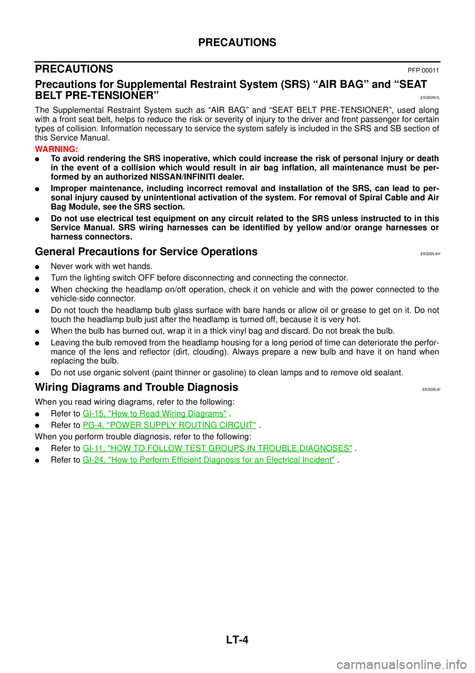
PRECAUTIONS
PRECAUTIONS
PFP:00011
Precautions for Supplemental Restraint System (SRS) “AIR BAG” and “SEAT
BELT PRE-TENSIONER”
EKS00N1L
The Supplemental Restraint System such as “AIR BAG” and “SEAT BELT PRE-TENSIONER”, used along
with a front seat belt, helps to reduce the risk or severity of injury to the driver and front passenger for certain
types of collision. Information necessary to service the system safely is included in the SRS and SB section of
this Service Manual.
WARNING:
lTo avoid rendering the SRS inoperative, which could increase the risk of personal injury or death
in the event of a collision which would result in air bag inflation, all maintenance must be per-
formed by an authorized NISSAN/INFINITI dealer.
lImproper maintenance, including incorrect removal and installation of the SRS, can lead to per-
sonal injury caused by unintentional activation of the system. For removal of Spiral Cable and Air
Bag Module, see the SRS section.
lDo not use electrical test equipment on any circuit related to the SRS unless instructed to in this
Service Manual. SRS wiring harnesses can be identified by yellow and/or orange harnesses or
harness connectors.
General Precautions for Service OperationsEKS00L4H
lNever work with wet hands.
lTurn the lighting switch OFF before disconnecting and connecting the connector.
lWhen checking the headlamp on/off operation, check it on vehicle and with the power connected to the
vehicle-side connector.
lDo not touch the headlamp bulb glass surface with bare hands or allow oil or grease to get on it. Do not
touch the headlamp bulb just after the headlamp is turned off, because it is very hot.
lWhen the bulb has burned out, wrap it in a thick vinyl bag and discard. Do not break the bulb.
lLeaving the bulb removed from the headlamp housing for a long period of time can deteriorate the perfor-
mance of the lens and reflector (dirt, clouding). Always prepare a new bulb and have it on hand when
replacing the bulb.
lDo not use organic solvent (paint thinner or gasoline) to clean lamps and to remove old sealant.
Wiring Diagrams and Trouble DiagnosisEKS00L4I
When you read wiring diagrams, refer to the following:
lRefer toGI-15, "How to Read Wiring Diagrams".
lRefer toPG-4, "POWER SUPPLY ROUTING CIRCUIT".
When you perform trouble diagnosis, refer to the following:
lRefer toGI-11, "HOW TO FOLLOW TEST GROUPS IN TROUBLE DIAGNOSES".
lRefer toGI-24, "How to Perform Efficient Diagnosis for an Electrical Incident".
Page 2185 of 3171

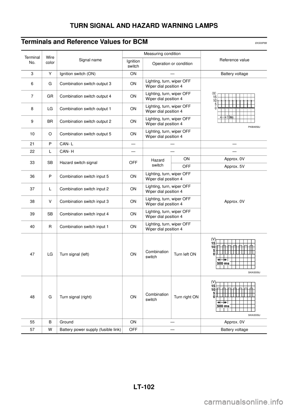
LT-102
TURN SIGNAL AND HAZARD WARNING LAMPS
Terminals and Reference Values for BCM
EKS00P89
Terminal
No.Wire
colorSignal nameMeasuring condition
Reference value
Ignition
switchOperation or condition
3 Y Ignition switch (ON) ON — Battery voltage
6 G Combination switch output 3 ONLighting, turn, wiper OFF
Wiper dial position 4
7 GR Combination switch output 4 ONLighting, turn, wiper OFF
Wiper dial position 4
8 LG Combination switch output 1 ONLighting, turn, wiper OFF
Wiper dial position 4
9 BR Combination switch output 2 ONLighting, turn, wiper OFF
Wiper dial position 4
10 O Combination switch output 5 ONLighting, turn, wiper OFF
Wiper dial position 4
21 P CAN- L — — —
22 L CAN- H — — —
33 SB Hazard switch signal OFFHazard
switchON Approx. 0V
OFF Approx. 5V
36 P Combination switch input 5 ONLighting, turn, wiper OFF
Wiper dial position 4
Approx. 0V 37 L Combination switch input 2 ONLighting, turn, wiper OFF
Wiper dial position 4
38 V Combination switch input 3 ONLighting, turn, wiper OFF
Wiper dial position 4
39 SB Combination switch input 4 ONLighting, turn, wiper OFF
Wiper dial position 4
40 R Combination switch input 1 ONLighting, turn, wiper OFF
Wiper dial position 4
47 LG Turn signal (left) ONCombination
switchTurn left ON
48 G Turn signal (right) ONCombination
switchTu rn righ t ON
55 B Ground ON — Approx. 0V
57 W Battery power supply (fusible link) OFF — Battery voltage
PKIB4958J
SKIA3009J
SKIA3009J
Page 2190 of 3171

TURN SIGNAL AND HAZARD WARNING LAMPS
LT-107
C
D
E
F
G
H
I
J
L
MA
B
LT
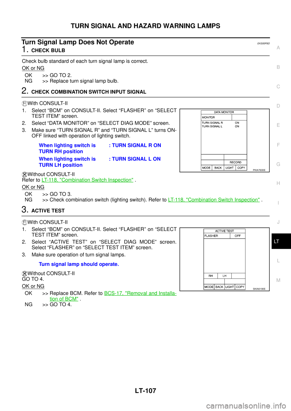
Turn Signal Lamp Does Not OperateEKS00P8D
1.CHECK BULB
Check bulb standard of each turn signal lamp is correct.
OK or NG
OK >> GO TO 2.
NG >> Replace turn signal lamp bulb.
2.CHECK COMBINATION SWITCH INPUT SIGNAL
With CONSULT-II
1. Select “BCM” on CONSULT-II. Select “FLASHER” on “SELECT
TEST ITEM” screen.
2. Select “DATA MONITOR” on “SELECT DIAG MODE” screen.
3. Make sure “TURN SIGNAL R” and “TURN SIGNAL L” turns ON-
OFF linked with operation of lighting switch.
Without CONSULT-II
Refer toLT- 11 8 , "
Combination Switch Inspection".
OK or NG
OK >> GO TO 3.
NG >> Check combination switch (lighting switch). Refer toLT- 11 8 , "
Combination Switch Inspection".
3.ACTIVE TEST
With CONSULT-II
1. Select “BCM” on CONSULT-II. Select “FLASHER” on “SELECT
TEST ITEM” screen.
2. Select “ACTIVE TEST” on “SELECT DIAG MODE” screen.
Select “FLASHER” on “SELECT TEST ITEM” screen.
3. Make sure operation of turn signal lamps.
Without CONSULT-II
GO TO 4.
OK or NG
OK >> Replace BCM. Refer toBCS-17, "Removal and Installa-
tion of BCM".
NG >> GO TO 4.When lighting switch is
TURN RH position: TURN SIGNAL R ON
When lighting switch is
TURN LH position: TURN SIGNAL L ON
PKIA7600E
Turn signal lamp should operate.
SKIA6190E