2005 NISSAN NAVARA warning light
[x] Cancel search: warning lightPage 969 of 3171
WARNING CHIME
DI-59
C
D
E
F
G
H
I
J
L
MA
B
DI
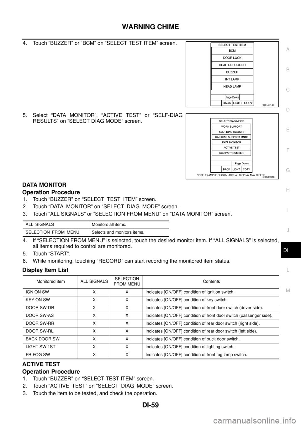
4. Touch “BUZZER” or “BCM” on “SELECT TEST ITEM” screen.
5. Select “DATA MONITOR”, “ACTIVE TEST” or “SELF-DIAG
RESULTS” on “SELECT DIAG MODE” screen.
DATA MONITOR
Operation Procedure
1. Touch “BUZZER” on “SELECT TEST ITEM” screen.
2. Touch “DATA MONITOR” on “SELECT DIAG MODE” screen.
3. Touch “ALL SIGNALS” or “SELECTION FROM MENU” on “DATA MONITOR” screen.
4. If “SELECTION FROM MENU” is selected, touch the desired monitor item. If “ALL SIGNALS” is selected,
all items required to control are monitored.
5. Touch “START”.
6. While monitoring, touching “RECORD” can start recording the monitored item status.
Display Item List
ACTIVE TEST
Operation Procedure
1. Touch “BUZZER” on “SELECT TEST ITEM” screen.
2. Touch “ACTIVE TEST” on “SELECT DIAG MODE” screen.
3. Touch the item to be tested, and check the operation.
PKIB4914E
BCIA0031E
ALL SIGNALS Monitors all items.
SELECTION FROM MENU Selects and monitors items.
Monitored item ALL SIGNALSSELECTION
FROM MENUContents
IGN ON SW X X Indicates [ON/OFF] condition of ignition switch.
KEY ON SW X X Indicates [ON/OFF] condition of key switch.
DOOR SW-DR X X Indicates [ON/OFF] condition of front door switch (driver side).
DOOR SW-AS X X Indicates [ON/OFF] condition of front door switch (passenger side).
DOOR SW-RR X X Indicates [ON/OFF] condition of rear door switch (right side).
DOOR SW-RL X X Indicates [ON/OFF] condition of rear door switch (left side).
BACK DOOR SW X X Indicates [ON/OFF] condition of buck door switch.
LIGHT SW 1ST X X Indicates [ON/OFF] condition of lighting switch.
FR FOG SW X X Indicates [ON/OFF] condition of front fog lamp switch.
Page 970 of 3171
DI-60
WARNING CHIME
4. During the operation check, touching “OFF” deactivates the operation.
Display Item List
SELF-DIAG RESULTS
Operation Procedure
1. Touch “BCM” on “SELECT TEST ITEM” screen.
2. Touch “SELF-DIAG RESULTS” on “SELECT DIAG MODE” screen.
3. Self-diagnosis results are displayed.
Display Item List
NOTE:
If “CAN communication [U1000]” is indicated, print the monitor item, and then go to “LAN System”. Refer to
LAN-3, "
Precautions When Using CONSULT-II".
Trouble DiagnosisEKS00L9I
HOW TO PERFORM TROUBLE DIAGNOSIS
1. Confirm the symptom and customer complaint.
2. Understand the outline of system. Refer toDI-51, "
System Description".
3. Perform the preliminary inspection. Refer toDI-60, "
PRELIMINARY INSPECTION".
4. Referring to trouble diagnosis chart, repair or replace the cause of the malfunction. Refer toDI-61,
"SYMPTOM CHART".
5. Does warning chime system operate normally? If it operates normally, GO TO 6. If not, GO TO 3.
6. INSPECTION END
PRELIMINARY INSPECTION
1.CHECK BCM (CONSULT-II)
Perform self-diagnosis of BCM.Refer toBCS-14, "
CONSULT-II Function (BCM)".
Self
-diagnosis results
No malfunction detected>>GO TO 2.
Malfunction detected>>Check applicable parts, and repair or replace corresponding parts.
2.CHECK COMBINATION METER (CONSULT-II)
Perform self-diagnosis of combination meter. Refer toDI-15, "
CONSULT-II Function (METER)".
Self
-diagnosis results
No malfunction detected>>INSPECTION END
Malfunction detected>>Check applicable parts, and repair or replace corresponding parts.
Test item Malfunction is detected when···
LIGHT WARN ALM This test is able to check light warning chime operation.
IGN KEY WARN ALM This test is able to check key warning chime operation.
KEY REMINDER WARN This test is able to check key reminder warning chime operation.
Monitored Item CONSULT-II display Description
CAN communication CAN communication [U1000] Malfunction is detected in CAN communication.
Page 971 of 3171
WARNING CHIME
DI-61
C
D
E
F
G
H
I
J
L
MA
B
DI
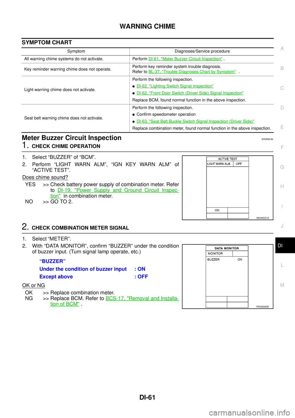
SYMPTOM CHART
Meter Buzzer Circuit InspectionEKS00L9L
1.CHECK CHIME OPERATION
1. Select “BUZZER” of “BCM”.
2. Perform “LIGHT WARN ALM”, “IGN KEY WARN ALM” of
“ACTIVE TEST”.
Does chime sound?
YES >> Check battery power supply of combination meter. Refer
toDI-19, "
Power Supply and Ground Circuit Inspec-
tion"in combination meter.
NO >> GO TO 2.
2.CHECK COMBINATION METER SIGNAL
1. Select “METER”.
2. With “DATA MONITOR”, confirm “BUZZER” under the condition
of buzzer input. (Turn signal lamp operate, etc.)
OK or NG
OK >> Replace combination meter.
NG >> Replace BCM. Refer toBCS-17, "
Removal and Installa-
tion of BCM".
Symptom Diagnoses/Service procedure
All warning chime systems do not activate. PerformDI-61, "
Meter Buzzer Circuit Inspection".
Key reminder warning chime does not operate.Perform key reminder system trouble diagnosis.
Refer toBL-37, "
Trouble Diagnoses Chart by Symptom".
Light warning chime does not activate.Perform the following inspection.
lDI-62, "Lighting Switch Signal Inspection"
lDI-62, "Front Door Switch (Driver Side) Signal Inspection"
Replace BCM, found normal function in the above inspection.
Seat belt warning chime does not activate.Perform the following inspection.
lConfirm speedometer operation
lDI-63, "Seat Belt Buckle Switch Signal Inspection (Driver Side)"
Replace combination meter, found normal function in the above inspection.
SKIA6331E
“BUZZER”
Under the condition of buzzer input : ON
Except above : OFF
PKIA2063E
Page 972 of 3171
DI-62
WARNING CHIME
Lighting Switch Signal Inspection
EKS00L9O
1.CHECK BCM INPUT SIGNAL
1. Select “BCM”.
2. With “DATA MONITOR” of “BUZZER”, confirm “LIGHT SW 1ST”
whenthelightingswitchisoperated.
OK or NG
OK >> Lighting switch signal is OK. Return toDI-61, "SYMP-
TOM CHART".
NG >> Check the lighting switch. Refer toLT- 11 8 , "
Combination
Switch Inspection".
Front Door Switch (Driver Side) Signal InspectionEKS00L9M
1.CHECK BCM INPUT SIGNAL
1. Select “BCM”.
2. With “DATA MONITOR” of “BUZZER”, confirm “DOOR SW-DR”
when the driver side door is opened/closed.
OK or NG
OK >> Front door switch (driver side) signal is OK. Return to
DI-61, "
SYMPTOM CHART".
NG >> GO TO 2.
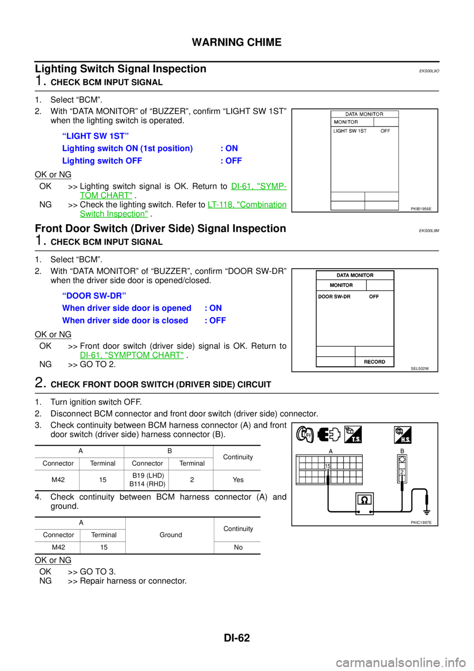
2.CHECK FRONT DOOR SWITCH (DRIVER SIDE) CIRCUIT
1. Turn ignition switch OFF.
2. Disconnect BCM connector and front door switch (driver side) connector.
3. Check continuity between BCM harness connector (A) and front
door switch (driver side) harness connector (B).
4. Check continuity between BCM harness connector (A) and
ground.
OK or NG
OK >> GO TO 3.
NG >> Repair harness or connector.“LIGHT SW 1ST”
Lighting switch ON (1st position) : ON
Lighting switch OFF : OFF
PKIB1956E
“DOOR SW-DR”
When driver side door is opened : ON
When driver side door is closed : OFF
SEL502W
AB
Continuity
Connector Terminal Connector Terminal
M42 15B19 (LHD)
B114 (RHD)2Yes
A
GroundContinuity
Connector Terminal
M42 15 No
PKIC1997E
Page 990 of 3171

EC-10
PRECAUTIONS
PRECAUTIONS
PFP:00001
Precautions for Supplemental Restraint System (SRS) “AIR BAG” and “SEAT
BELT PRE-TENSIONER”
EBS01KC5
The Supplemental Restraint System such as “AIR BAG” and “SEAT BELT PRE-TENSIONER”, used along
with a front seat belt, helps to reduce the risk or severity of injury to the driver and front passenger for certain
types of collision. Information necessary to service the system safely is included in the SRS and SB section of
this Service Manual.
WARNING:
lTo avoid rendering the SRS inoperative, which could increase the risk of personal injury or death
in the event of a collision which would result in air bag inflation, all maintenance must be per-
formed by an authorized NISSAN/INFINITI dealer.
lImproper maintenance, including incorrect removal and installation of the SRS, can lead to per-
sonal injury caused by unintentional activation of the system. For removal of Spiral Cable and Air
Bag Module, see the SRS section.
lDo not use electrical test equipment on any circuit related to the SRS unless instructed to in this
Service Manual. SRS wiring harnesses can be identified by yellow and/or orange harnesses or
harness connectors.
On Board Diagnostic (OBD) System of EngineEBS01KC6
The ECM has an on board diagnostic system. It will light up the malfunction indicator (MI) to warn the driver of
a malfunction causing emission deterioration.
CAUTION:
lBe sure to turn the ignition switch OFF and disconnect the battery negative cable before any
repair or inspection work. The open/short circuit of related switches, sensors, solenoid valves,
etc. will cause the MI to light up.
lBe sure to connect and lock the connectors securely after work. A loose (unlocked) connector will
cause the MI to light up due to the open circuit. (Be sure the connector is free from water, grease,
dirt, bent terminals, etc.)
lCertain systems and components, especially those related to OBD, may use a new style slide-
locking type harness connector. For description and how to disconnect, refer toPG-75, "
HAR-
NESS CONNECTOR".
lBe sure to route and secure the harnesses properly after work. The interference of the harness
with a bracket, etc. may cause the MI to light up due to the short circuit.
lBe sure to connect rubber tubes properly after work. A misconnected or disconnected rubber tube
may cause the MI to light up due to the malfunction of the fuel system, etc.
lBe sure to erase the unnecessary malfunction information (repairs completed) from the ECM
before returning the vehicle to the customer.
PrecautionsEBS01KC7
lAlways use a 12 volt battery as power source.
lDo not attempt to disconnect battery cables while engine is
running.
lBefore connecting or disconnecting the ECM harness con-
nector, turn ignition switch OFF and disconnect battery
negative cable. Failure to do so may damage the ECM
because battery voltage is applied to ECM even if ignition
switch is turned off.
lBefore removing parts, turn ignition switch OFF and then
disconnect battery negative cable.
SEF289H
Page 1009 of 3171
ON BOARD DIAGNOSTIC (OBD) SYSTEM
EC-29
C
D
E
F
G
H
I
J
K
L
MA
EC
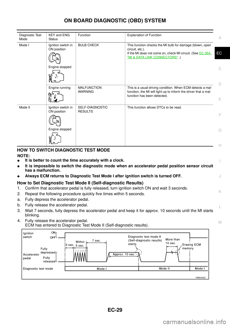
HOWTOSWITCHDIAGNOSTICTESTMODE
NOTE:
lIt is better to count the time accurately with a clock.
lIt is impossible to switch the diagnostic mode when an accelerator pedal position sensor circuit
has a malfunction.
lAlways ECM returns to Diagnostic Test Mode I after ignition switch is turned OFF.
How to Set Diagnostic Test Mode II (Self-diagnostic Results)
1. Confirm that accelerator pedal is fully released, turn ignition switch ON and wait 3 seconds.
2. Repeat the following procedure quickly five times within 5 seconds.
a. Fully depress the accelerator pedal.
b. Fully release the accelerator pedal.
3. Wait 7 seconds, fully depress the accelerator pedal and keep it for approx. 10 seconds until the MI starts
blinking.
4. Fully release the accelerator pedal.
ECM has entered to Diagnostic Test Mode II (Self-diagnostic results).
Diagnostic Test
ModeKEY and ENG.
Statu sFunction Explanation of Function
Mode I Ignition switch in
ON position
Engine stoppedBULB CHECK This function checks the MI bulb for damage (blown, open
circuit, etc.).
If the MI does not come on, check MI circuit. (SeeEC-354,
"MI&DATA LINK CONNECTORS".)
Engine running MALFUNCTION
WARNINGThis is a usual driving condition. When ECM detects a mal-
function, the MI will light up to inform the driver that a mal-
function has been detected.
Mode II Ignition switch in
ON position
Engine stoppedSELF-DIAGNOSTIC
RESULTSThis function allows DTCs to be read.
PBIB0092E
Page 1610 of 3171
FSU-10
COIL SPRING AND SHOCK ABSORBER
COIL SPRING AND SHOCK ABSORBER
PFP:56210
Removal and InstallationEES002KO
REMOVAL
1. Remove the wheel.
2. Support the lower link using a suitable jack.
3. Remove connecting rod upper joints from stabilizer bar. Refer toFSU-6, "
Components".
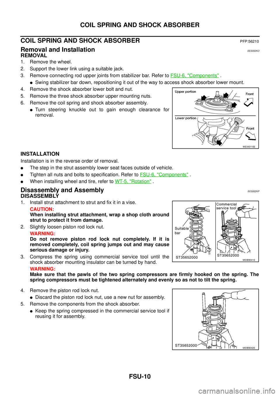
lSwing stabilizer bar down, repositioning it out of the way to access shock absorber lower mount.
4. Remove the shock absorber lower bolt and nut.
5. Remove the three shock absorber upper mounting nuts.
6. Remove the coil spring and shock absorber assembly.
lTurn steering knuckle out to gain enough clearance for
removal.
INSTALLATION
Installation is in the reverse order of removal.
lThe step in the strut assembly lower seat faces outside of vehicle.
lTighten all nuts and bolts to specification. Refer toFSU-6, "Components".
lWhen installing wheel and tire, refer toWT-5, "Rotation".
Disassembly and AssemblyEES002KP
DISASSEMBLY
1. Install strut attachment to strut and fix it in a vise.
CAUTION:
When installing strut attachment, wrap a shop cloth around
strut to protect it from damage.
2. Slightly loosen piston rod lock nut.
WARNING:
Do not remove piston rod lock nut completely. If it is
removed completely, coil spring jumps out and may cause
serious damage or injury.
3. Compress the spring using commercial service tool until the
shock absorber mounting insulator can be turned by hand.
WARNING:
Make sure that the pawls of the two spring compressors are firmly hooked on the spring. The
spring compressors must be tightened alternately and evenly so as not to tilt the spring.
4. Remove the piston rod lock nut.
lDiscard the piston rod lock nut, use a new nut for assembly.
5. Remove the components from the shock absorber.
lKeep the spring compressed in the commercial service tool if
reusing it for assembly.
WEIA0116E
MEIB9041E
MEIB9042E
Page 1625 of 3171

PRECAUTIONS
GI-3
C
D
E
F
G
H
I
J
K
L
MB
GI
PRECAUTIONSPFP:00001
DescriptionEAS001GG
Observe the following precautions to ensure safe and proper servicing. These precautions are not
described in each individual section.
Precautions for Supplemental Restraint System (SRS) “AIR BAG” and “SEAT
BELT PRE-TENSIONER”
EAS001GH
The Supplemental Restraint System such as “AIR BAG” and “SEAT BELT PRE-TENSIONER”, used along
with a front seat belt, helps to reduce the risk or severity of injury to the driver and front passenger for certain
types of collision. Information necessary to service the system safely is included in the SRS and SB section of
this Service Manual.
WARNING:
lTo avoid rendering the SRS inoperative, which could increase the risk of personal injury or death
in the event of a collision which would result in air bag inflation, all maintenance must be per-
formed by an authorized NISSAN/INFINITI dealer.
lImproper maintenance, including incorrect removal and installation of the SRS, can lead to per-
sonal injury caused by unintentional activation of the system. For removal of Spiral Cable and Air
Bag Module, see the SRS section.
lDo not use electrical test equipment on any circuit related to the SRS unless instructed to in this
Service Manual. SRS wiring harnesses can be identified by yellow and/or orange harnesses or
harness connectors.
Precautions for NATS (NISSAN ANTI-THEFT SYSTEM)EAS001GI
NATS will immobilize the engine if someone tries to start it without the registered key of NATS.
Both of the originally supplied ignition key IDs have been NATS registered.
The security indicator is located on the instrument panel. The indicator blinks when the immobilizer system is
functioning.
Therefore, NATS warns outsiders that the vehicle is equipped with the anti-theft system.
lWhen NATS detects trouble, the security indicator lamp lights up while ignition switch is in "ON" position.
This lighting up indicates that the anti-theft is not functioning, so prompt service is required.
lWhen servicing NATS (trouble diagnoses, system initialization and additional registration of other NATS
ignition key IDs), CONSULT-II hardware and CONSULT-II NATS software is necessary.
Regarding the procedures of NATS initialization and NATS ignition key ID registration, refer to CONSULT-
II operation manual, NATS.
Therefore, CONSULT-II NATS software (program card and operation manual) must be kept strictly con-
fidential to maintain the integrity of the anti-theft function.
lWhen servicing NATS (trouble diagnoses, system initialization and additional registration of other NATS
ignition key IDs), it may be necessary to re-register original key identification. Therefore, be sure to
receive all keys from vehicle owner. A maximum of four or five key IDs can be registered into NATS.
lWhen failing to start the engine first time using the key of NATS, start as follows.
1. Leave the ignition key in "ON" position for approximately 5 seconds.
2. Turn ignition key to "OFF" or "LOCK" position and wait approximately 5 seconds.
3. Repeat step 1 and 2 again.
4. Restart the engine while keeping the key separate from any others on key-chain.
Precautions Necessary for Steering Wheel Rotation After Battery DisconnectEAS001HY
NOTE:
lThis Procedure is applied only to models with Intelligent Key system and NATS (NISSAN ANTI-THEFT
SYSTEM).
lRemove and install all control units after disconnecting both battery cables with the ignition knob in the
²LOCK²position.
lAlways use CONSULT-II to perform self-diagnosis as a part of each function inspection after finishing
work. If DTC is detected, perform trouble diagnosis according to self-diagnostic results.
For models equipped with the Intelligent Key system and NATS, an electrically controlled steering lock mech-
anism is adopted on the key cylinder.