2005 NISSAN NAVARA transmission
[x] Cancel search: transmissionPage 197 of 3171
TROUBLE DIAGNOSIS FOR SYMPTOMS
AT-189
D
E
F
G
H
I
J
K
L
MA
B
AT
6.DETECT MALFUNCTIONING ITEM
1. Check control valve with TCM. Refer toAT- 2 1 8 , "
Control Valve With TCM and A/T Fluid Temperature Sen-
sor 2".
2. Disassemble A/T. Refer toAT- 2 6 3 , "
DISASSEMBLY".
3. Check the following.
–Oil pump assembly. Refer toAT- 2 8 1 , "Oil Pump".
–Power train system. Refer toAT- 2 6 3 , "DISASSEMBLY".
–Transmission case. Refer toAT- 2 6 3 , "DISASSEMBLY".
OK or NG
OK >> GO TO 7.
NG >> Repair or replace damaged parts.
7.CHECK A/T FLUID CONDITION
1. Remove oil pan. Refer toAT- 2 1 8 , "
Control Valve With TCM and A/T Fluid Temperature Sensor 2".
2. Check A/T fluid condition. Refer toAT-43, "
A/T Fluid Condition Check".
OK or NG
OK >> GO TO 8.
NG >> GO TO 11.
8.DETECT MALFUNCTIONING ITEM
Check malfunction items. If any items are damaged, repair or replace damaged parts. Refer toAT-53, "
Symp-
tom Chart"(Symptom No.10).
OK or NG
OK >> GO TO 9.
NG >> Repair or replace damaged parts.
9.CHECK SYMPTOM
Check again. Refer toAT-48, "
Cruise Test - Part 1",AT-50, "Cruise Test - Part 2".
OK or NG
OK >>INSPECTION END
NG >> GO TO 10.
10.CHECK TCM
1. Check TCM input/output signals. Refer toAT-76, "
TCM Input/Output Signal Reference Values".
2. If NG, recheck A/T assembly harness connector terminals for damage or loose connection with harness
connector.
OK or NG
OK >>INSPECTION END
NG >> Repair or replace damaged parts.
11 .DETECT MALFUNCTIONING ITEM
Check malfunction items. If any items are damaged, repair or replace damaged parts. Refer toAT-53, "
Symp-
tom Chart"(Symptom No.10).
OK or NG
OK >> GO TO 9.
NG >> Repair or replace damaged parts.
Page 199 of 3171
TROUBLE DIAGNOSIS FOR SYMPTOMS
AT-191
D
E
F
G
H
I
J
K
L
MA
B
AT
6.DETECT MALFUNCTIONING ITEM
1. Check control valve with TCM. Refer toAT- 2 1 8 , "
Control Valve With TCM and A/T Fluid Temperature Sen-
sor 2".
2. Disassemble A/T. Refer toAT- 2 6 3 , "
DISASSEMBLY".
3. Check the following.
–Oil pump assembly. Refer toAT- 2 8 1 , "Oil Pump".
–Power train system. Refer toAT- 2 6 3 , "DISASSEMBLY".
–Transmission case. Refer toAT- 2 6 3 , "DISASSEMBLY".
OK or NG
OK >> GO TO 7.
NG >> Repair or replace damaged parts.
7.CHECK A/T FLUID CONDITION
1. Remove oil pan. Refer toAT- 2 1 8 , "
Control Valve With TCM and A/T Fluid Temperature Sensor 2".
2. Check A/T fluid condition. Refer toAT-43, "
A/T Fluid Condition Check".
OK or NG
OK >> GO TO 8.
NG >> GO TO 11.
8.DETECT MALFUNCTIONING ITEM
Check malfunction items. If any items are damaged, repair or replace damaged parts. Refer toAT-53, "
Symp-
tom Chart"(Symptom No.11).
OK or NG
OK >> GO TO 9.
NG >> Repair or replace damaged parts.
9.CHECK SYMPTOM
Check again. Refer toAT-48, "
Cruise Test - Part 1",AT-50, "Cruise Test - Part 2".
OK or NG
OK >>INSPECTION END
NG >> GO TO 10.
10.CHECK TCM
1. Check TCM input/output signals. Refer toAT-76, "
TCM Input/Output Signal Reference Values".
2. If NG, recheck A/T assembly harness connector terminals for damage or loose connection with harness
connector.
OK or NG
OK >>INSPECTION END
NG >> Repair or replace damaged parts.
11 .DETECT MALFUNCTIONING ITEM
Check malfunction items. If any items are damaged, repair or replace damaged parts. Refer toAT-53, "
Symp-
tom Chart"(Symptom No.11).
OK or NG
OK >> GO TO 9.
NG >> Repair or replace damaged parts.
Page 201 of 3171
TROUBLE DIAGNOSIS FOR SYMPTOMS
AT-193
D
E
F
G
H
I
J
K
L
MA
B
AT
6.DETECT MALFUNCTIONING ITEM
1. Check control valve with TCM. Refer toAT- 2 1 8 , "
Control Valve With TCM and A/T Fluid Temperature Sen-
sor 2".
2. Disassemble A/T. Refer toAT- 2 6 3 , "
DISASSEMBLY".
3. Check the following.
–Oil pump assembly. Refer toAT- 2 8 1 , "Oil Pump".
–Power train system. Refer toAT- 2 6 3 , "DISASSEMBLY".
–Transmission case. Refer toAT- 2 6 3 , "DISASSEMBLY".
OK or NG
OK >> GO TO 7.
NG >> Repair or replace damaged parts.
7.CHECK A/T FLUID CONDITION
1. Remove oil pan. Refer toAT- 2 1 8 , "
Control Valve With TCM and A/T Fluid Temperature Sensor 2".
2. Check A/T fluid condition. Refer toAT-43, "
A/T Fluid Condition Check".
OK or NG
OK >> GO TO 8.
NG >> GO TO 11.
8.DETECT MALFUNCTIONING ITEM
Check malfunction items. If any items are damaged, repair or replace damaged parts. Refer toAT-53, "
Symp-
tom Chart"(Symptom No.12).
OK or NG
OK >> GO TO 9.
NG >> Repair or replace damaged parts.
9.CHECK SYMPTOM
Check again. Refer toAT-48, "
Cruise Test - Part 1",AT-50, "Cruise Test - Part 2".
OK or NG
OK >>INSPECTION END
NG >> GO TO 10.
10.CHECK TCM
1. Check TCM input/output signals. Refer toAT-76, "
TCM Input/Output Signal Reference Values".
2. If NG, recheck A/T assembly harness connector terminals for damage or loose connection with harness
connector.
OK or NG
OK >>INSPECTION END
NG >> Repair or replace damaged parts.
11 .DETECT MALFUNCTIONING ITEM
Check malfunction items. If any items are damaged, repair or replace damaged parts. Refer toAT-53, "
Symp-
tom Chart"(Symptom No.12).
OK or NG
OK >> GO TO 9.
NG >> Repair or replace damaged parts.
Page 203 of 3171
TROUBLE DIAGNOSIS FOR SYMPTOMS
AT-195
D
E
F
G
H
I
J
K
L
MA
B
AT
7.DETECT MALFUNCTIONING ITEM
1. Check control valve with TCM. Refer toAT- 2 1 8 , "
Control Valve With TCM and A/T Fluid Temperature Sen-
sor 2".
2. Disassemble A/T. Refer toAT- 2 6 3 , "
DISASSEMBLY".
3. Check the following.
–Oil pump assembly. Refer toAT- 2 8 1 , "Oil Pump".
–Power train system. Refer toAT- 2 6 3 , "DISASSEMBLY".
–Transmission case. Refer toAT- 2 6 3 , "DISASSEMBLY".
OK or NG
OK >> GO TO 8.
NG >> Repair or replace damaged parts.
8.CHECK A/T FLUID CONDITION
1. Remove oil pan. Refer toAT- 2 1 8 , "
Control Valve With TCM and A/T Fluid Temperature Sensor 2".
2. Check A/T fluid condition. Refer toAT-43, "
A/T Fluid Condition Check".
OK or NG
OK >> GO TO 9.
NG >> GO TO 12.
9.DETECT MALFUNCTIONING ITEM
Check malfunction items. If any items are damaged, repair or replace damaged parts. Refer toAT-53, "
Symp-
tom Chart"(Symptom No.13).
OK or NG
OK >> GO TO 10.
NG >> Repair or replace damaged parts.
10.CHECK SYMPTOM
Check again. Refer toAT-48, "
Cruise Test - Part 1".
OK or NG
OK >>INSPECTION END
NG >> GO TO 11.
11 .CHECK TCM
1. Check TCM input/output signals. Refer toAT-76, "
TCM Input/Output Signal Reference Values".
2. If NG, recheck A/T assembly harness connector terminals for damage or loose connection with harness
connector.
OK or NG
OK >>INSPECTION END
NG >> Repair or replace damaged parts.
12.DETECT MALFUNCTIONING ITEM
Check malfunction items. If any items are damaged, repair or replace damaged parts. Refer toAT-53, "
Symp-
tom Chart"(Symptom No.13).
OK or NG
OK >> GO TO 10.
NG >> Repair or replace damaged parts.
Page 204 of 3171
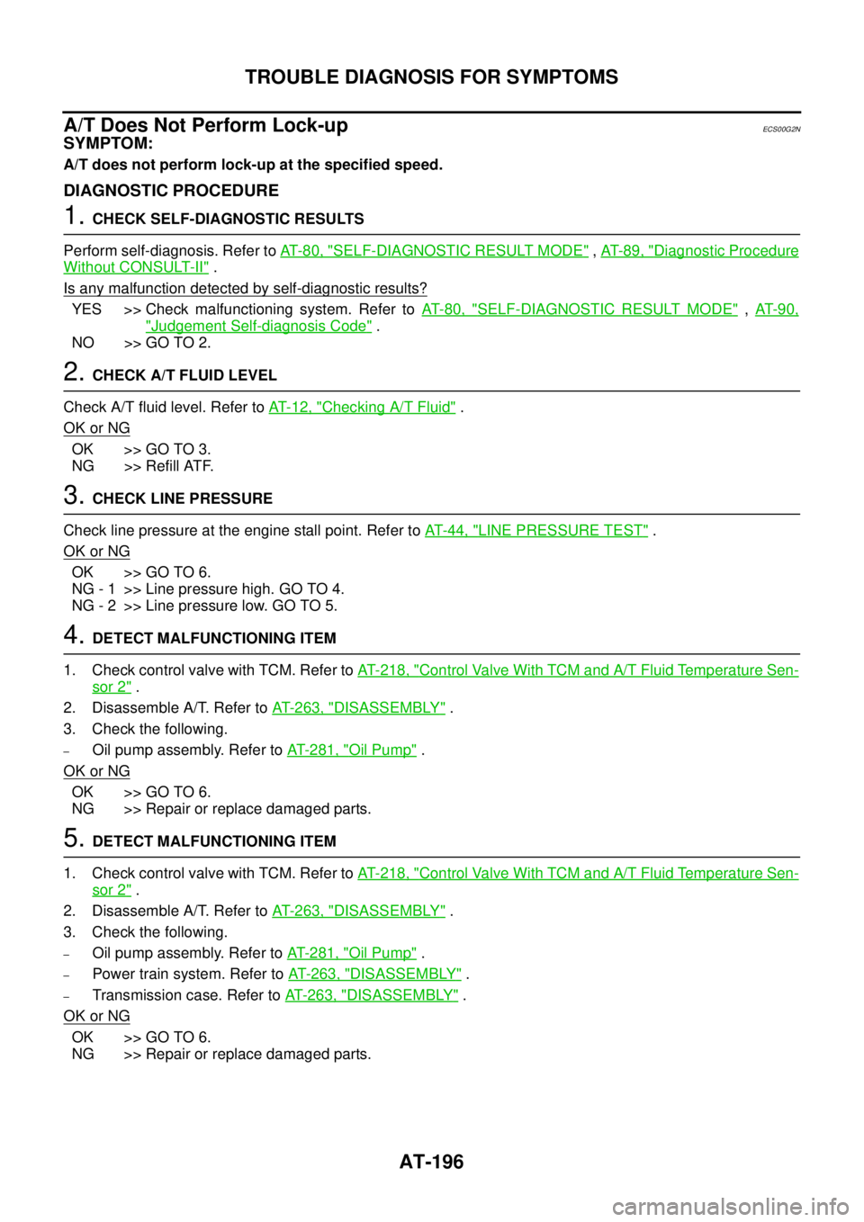
AT-196
TROUBLE DIAGNOSIS FOR SYMPTOMS
A/T Does Not Perform Lock-up
ECS00G2N
SYMPTOM:
A/T does not perform lock-up at the specified speed.
DIAGNOSTIC PROCEDURE
1.CHECK SELF-DIAGNOSTIC RESULTS
Perform self-diagnosis. Refer toAT-80, "
SELF-DIAGNOSTIC RESULT MODE",AT-89, "Diagnostic Procedure
Without CONSULT-II".
Is any malfunction detected by self-diagnostic results?
YES >> Check malfunctioning system. Refer toAT-80, "SELF-DIAGNOSTIC RESULT MODE",AT- 9 0 ,
"Judgement Self-diagnosis Code".
NO >> GO TO 2.
2.CHECK A/T FLUID LEVEL
Check A/T fluid level. Refer toAT-12, "
Checking A/T Fluid".
OK or NG
OK >> GO TO 3.
NG >> Refill ATF.
3.CHECK LINE PRESSURE
Check line pressure at the engine stall point. Refer toAT-44, "
LINE PRESSURE TEST".
OK or NG
OK >> GO TO 6.
NG - 1 >> Line pressure high. GO TO 4.
NG - 2 >> Line pressure low. GO TO 5.
4.DETECT MALFUNCTIONING ITEM
1. Check control valve with TCM. Refer toAT- 2 1 8 , "
Control Valve With TCM and A/T Fluid Temperature Sen-
sor 2".
2. Disassemble A/T. Refer toAT- 2 6 3 , "
DISASSEMBLY".
3. Check the following.
–Oil pump assembly. Refer toAT- 2 8 1 , "Oil Pump".
OK or NG
OK >> GO TO 6.
NG >> Repair or replace damaged parts.
5.DETECT MALFUNCTIONING ITEM
1. Check control valve with TCM. Refer toAT- 2 1 8 , "
Control Valve With TCM and A/T Fluid Temperature Sen-
sor 2".
2. Disassemble A/T. Refer toAT- 2 6 3 , "
DISASSEMBLY".
3. Check the following.
–Oil pump assembly. Refer toAT- 2 8 1 , "Oil Pump".
–Power train system. Refer toAT- 2 6 3 , "DISASSEMBLY".
–Transmission case. Refer toAT- 2 6 3 , "DISASSEMBLY".
OK or NG
OK >> GO TO 6.
NG >> Repair or replace damaged parts.
Page 229 of 3171
ON-VEHICLE SERVICE
AT-221
D
E
F
G
H
I
J
K
L
MA
B
AT
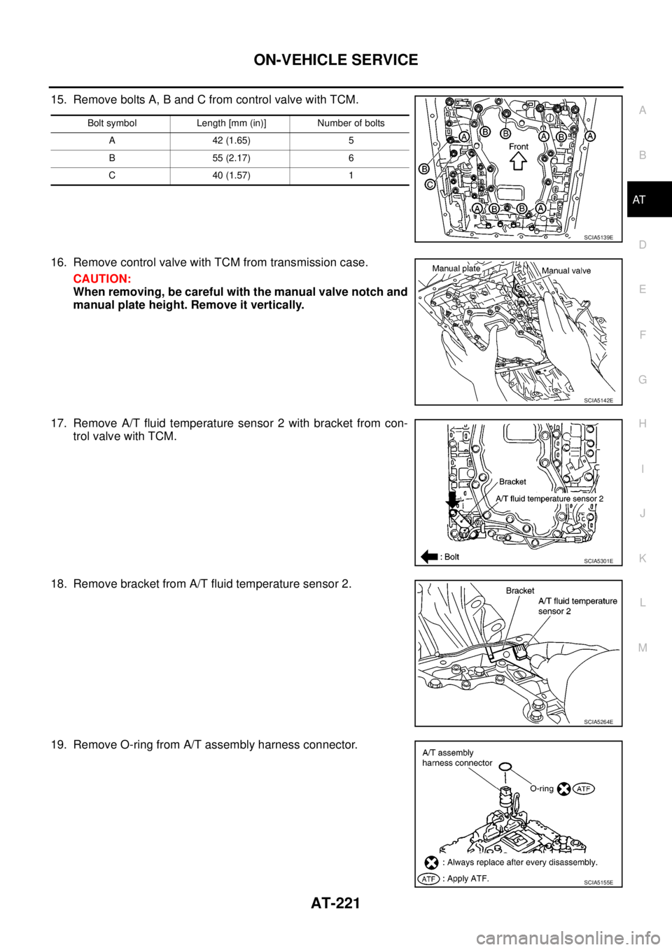
15. Remove bolts A, B and C from control valve with TCM.
16. Remove control valve with TCM from transmission case.
CAUTION:
When removing, be careful with the manual valve notch and
manual plate height. Remove it vertically.
17. Remove A/T fluid temperature sensor 2 with bracket from con-
trol valve with TCM.
18. Remove bracket from A/T fluid temperature sensor 2.
19. Remove O-ring from A/T assembly harness connector.
Bolt symbol Length [mm (in)] Number of bolts
A42(1.65) 5
B55(2.17) 6
C40(1.57) 1
SCIA5139E
SCIA5142E
SCIA5301E
SCIA5264E
SCIA5155E
Page 232 of 3171
AT-224
ON-VEHICLE SERVICE
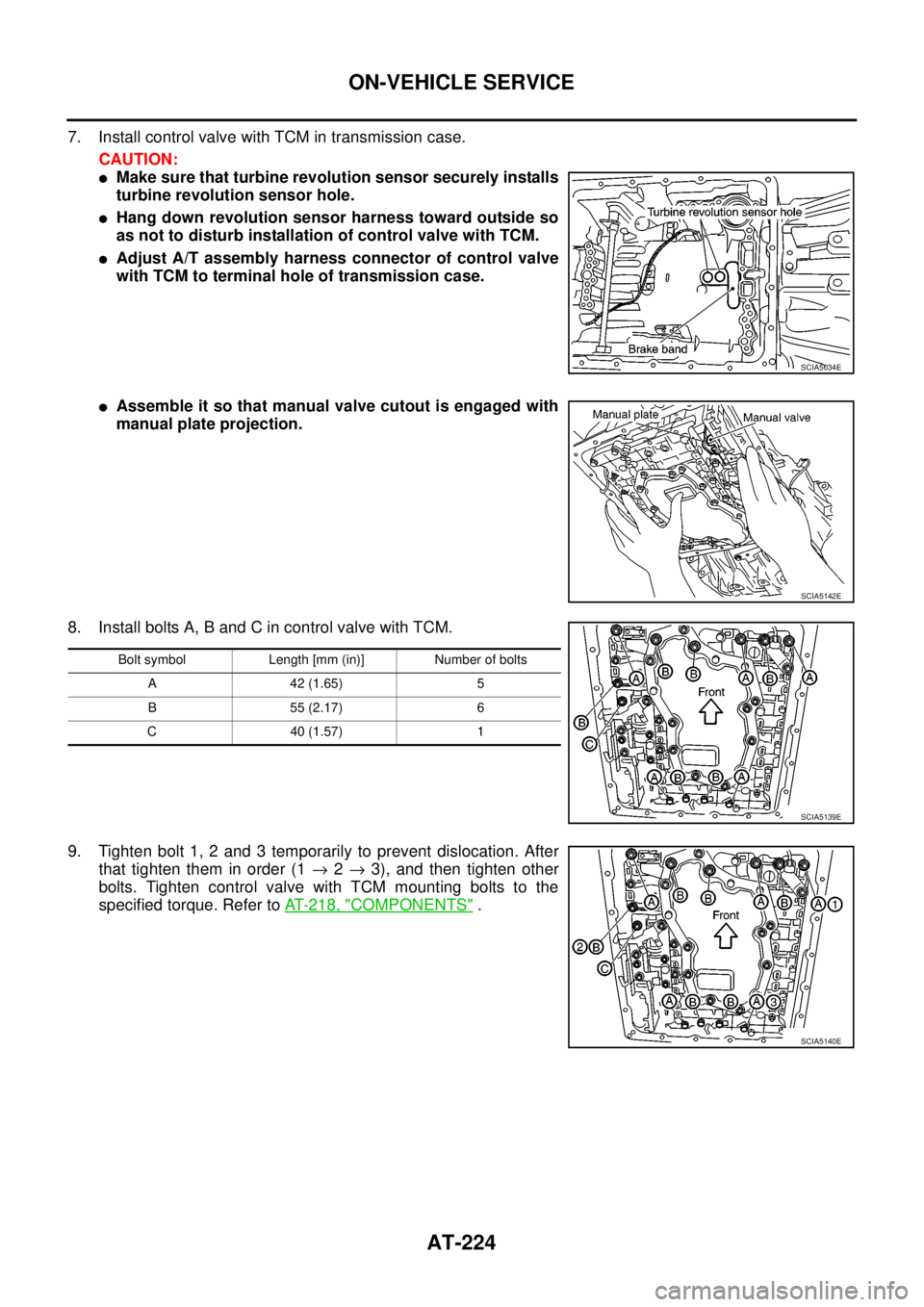
7. Install control valve with TCM in transmission case.
CAUTION:
lMake sure that turbine revolution sensor securely installs
turbine revolution sensor hole.
lHang down revolution sensor harness toward outside so
as not to disturb installation of control valve with TCM.
lAdjust A/T assembly harness connector of control valve
with TCM to terminal hole of transmission case.
lAssemble it so that manual valve cutout is engaged with
manual plate projection.
8. Install bolts A, B and C in control valve with TCM.
9. Tighten bolt 1, 2 and 3 temporarily to prevent dislocation. After
that tighten them in order (1®2®3), and then tighten other
bolts. Tighten control valve with TCM mounting bolts to the
specified torque. Refer toAT- 2 1 8 , "
COMPONENTS".
SCIA5034E
SCIA5142E
Bolt symbol Length [mm (in)] Number of bolts
A 42 (1.65) 5
B 55 (2.17) 6
C 40 (1.57) 1
SCIA5139E
SCIA5140E
Page 234 of 3171
AT-226
ON-VEHICLE SERVICE
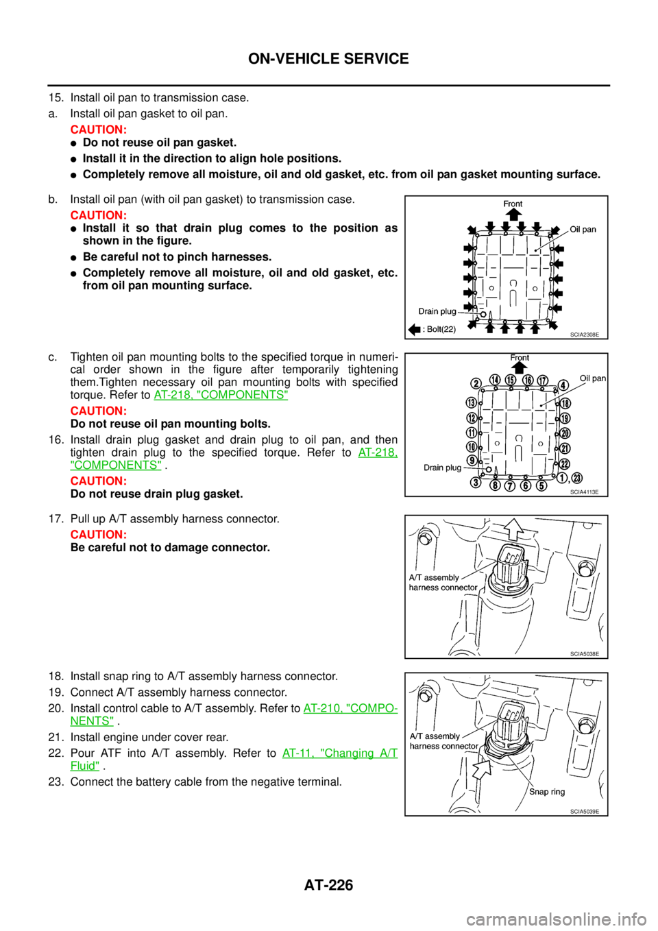
15. Install oil pan to transmission case.
a. Install oil pan gasket to oil pan.
CAUTION:
lDo not reuse oil pan gasket.
lInstall it in the direction to align hole positions.
lCompletely remove all moisture, oil and old gasket, etc. from oil pan gasket mounting surface.
b. Install oil pan (with oil pan gasket) to transmission case.
CAUTION:
lInstall it so that drain plug comes to the position as
shown in the figure.
lBe careful not to pinch harnesses.
lCompletely remove all moisture, oil and old gasket, etc.
from oil pan mounting surface.
c. Tighten oil pan mounting bolts to the specified torque in numeri-
cal order shown in the figure after temporarily tightening
them.Tighten necessary oil pan mounting bolts with specified
torque. Refer toAT- 2 1 8 , "
COMPONENTS"
CAUTION:
Do not reuse oil pan mounting bolts.
16. Install drain plug gasket and drain plug to oil pan, and then
tighten drain plug to the specified torque. Refer toAT-218,
"COMPONENTS".
CAUTION:
Do not reuse drain plug gasket.
17. Pull up A/T assembly harness connector.
CAUTION:
Be careful not to damage connector.
18. Install snap ring to A/T assembly harness connector.
19. Connect A/T assembly harness connector.
20. Install control cable to A/T assembly. Refer toAT- 2 1 0 , "
COMPO-
NENTS".
21. Install engine under cover rear.
22. Pour ATF into A/T assembly. Refer toAT-11, "
Changing A/T
Fluid".
23. Connect the battery cable from the negative terminal.
SCIA2308E
SCIA4113E
SCIA5038E
SCIA5039E