2005 NISSAN NAVARA transmission
[x] Cancel search: transmissionPage 39 of 3171
A/T CONTROL SYSTEM
AT-31
D
E
F
G
H
I
J
K
L
MA
B
AT
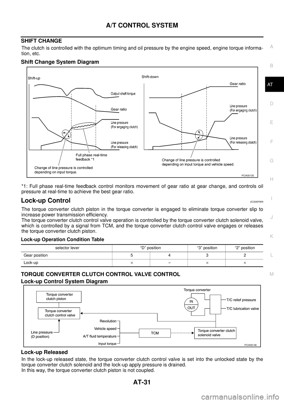
SHIFT CHANGE
The clutch is controlled with the optimum timing and oil pressure by the engine speed, engine torque informa-
tion, etc.
Shift Change System Diagram
*1: Full phase real-time feedback control monitors movement of gear ratio at gear change, and controls oil
pressure at real-time to achieve the best gear ratio.
Lock-up ControlECS00FWN
The torque converter clutch piston in the torque converter is engaged to eliminate torque converter slip to
increase power transmission efficiency.
The torque converter clutch control valve operation is controlled by the torque converter clutch solenoid valve,
which is controlled by a signal from TCM, and the torque converter clutch control valve engages or releases
the torque converter clutch piston.
Lock-up Operation Condition Table
TORQUE CONVERTER CLUTCH CONTROL VALVE CONTROL
Lock-up Control System Diagram
Lock-up Released
In the lock-up released state, the torque converter clutch control valve is set into the unlocked state by the
torque converter clutch solenoid and the lock-up apply pressure is drained.
In this way, the torque converter clutch piston is not coupled.
PCIA0013E
selector lever “D” position “3” position “2” position
Gear position 5 4 3 2
Lock-up´–´´
PCIA0014E
Page 42 of 3171

AT-34
TROUBLE DIAGNOSIS
TROUBLE DIAGNOSIS
PFP:00004
DTC Inspection Priority ChartECS00FWV
If some DTCs are displayed at the same time, perform inspections one by one based on the following priority
chart.
NOTE:
If DTC “U1000 CAN COMM CIRCUIT” is displayed with other DTCs, first perform the trouble diagnosis
for “DTC U1000 CAN COMMUNICATION LINE”. Refer toAT-91
.
Fail-safeECS00FWW
The TCM has an electrical fail-safe mode. This mode makes it possible to operate even if there is an error in a
main electronic control input/output signal circuit. In fail-safe mode A/T is fixed in 2nd, 4th or 5th (depending
on the breakdown position), so the customer should feel “slipping” or “poor acceleration”.
Even when the electronic circuits are normal, under special conditions (for example, when slamming on the
brake with the wheels spinning drastically and stopping the tire rotation), the transmission can go into fail-safe
mode. If this happens, switch OFF the ignition switch for 10 seconds, then switch it ON again to return to the
normal shift pattern. Therefore, the customer's vehicle has returned to normal, so handle according toAT- 3 7 ,
"WORK FLOW".
FAIL-SAFE FUNCTION
If any malfunction occurs in a sensor or solenoid, this function controls the A/T to mark driving possible.
Vehicle Speed Sensor
Signals are input from two systems - from vehicle speed sensor A/T (revolution sensor) installed on the A/T
and from combination meter so normal driving is possible even if there is a malfunction in one of the systems.
And if vehicle speed sensor A/T (revolution sensor) has unusual cases, 5th gear is prohibited.
Accelerator Pedal Position Sensor
If there is a malfunction in one of the systems, the accelerator opening angle is controlled by ECM according
to a pre-determined accelerator angle to make driving possible. And if there are malfunctions in tow systems,
the engine speed is fixed by ECM to a pre-determined engine speed to make driving possible.
PNP Switch
In the unlikely event that a malfunction signal enters the TCM, the position indicator is switched OFF, the
starter relay is switched OFF (starter starting is disabled), the back-up lamp relay switched OFF (back-up lamp
is OFF) and the position is fixed to the “D” position to make driving possible.
Starter Relay
The starter relay is switched OFF. (Starter starting is disabled.)
Priority Detected items (DTC)
1 U1000 CAN communication line
2 Except above
Page 99 of 3171
DTC U1000 CAN COMMUNICATION LINE
AT-91
D
E
F
G
H
I
J
K
L
MA
B
AT
DTC U1000 CAN COMMUNICATION LINEPFP:23710
DescriptionECS00FXC
CAN (Controller Area Network) is a serial communication line for real time application. It is an on-vehicle mul-
tiplex communication line with high data communication speed and excellent malfunction detection ability.
Many electronic control units are equipped onto a vehicle, and each control unit shares information and links
with other control units during operation (not independent). In CAN communication, control units are con-
nected with 2 communication lines (CAN H line, CAN L line) allowing a high rate of information transmission
with less wiring. Each control unit transmits/receives data but selectively reads required data only.
On Board Diagnosis LogicECS00FXD
Diagnostic trouble code “U1000 CAN COMM CIRCUIT” with CONSULT-II or 17th judgement flicker without
CONSULT-II is detected when TCM cannot communicate to other control units.
Possible CauseECS00FXE
Harness or connectors
(CAN communication line is open or shorted.)
DTC Confirmation ProcedureECS00FXF
NOTE:
If “DTC Confirmation Procedure” has been previously performed, always turn ignition switch OFF and
wait at least 10 seconds before performing the next test.
After the repair, perform the following procedure to confirm the malfunction is eliminated.
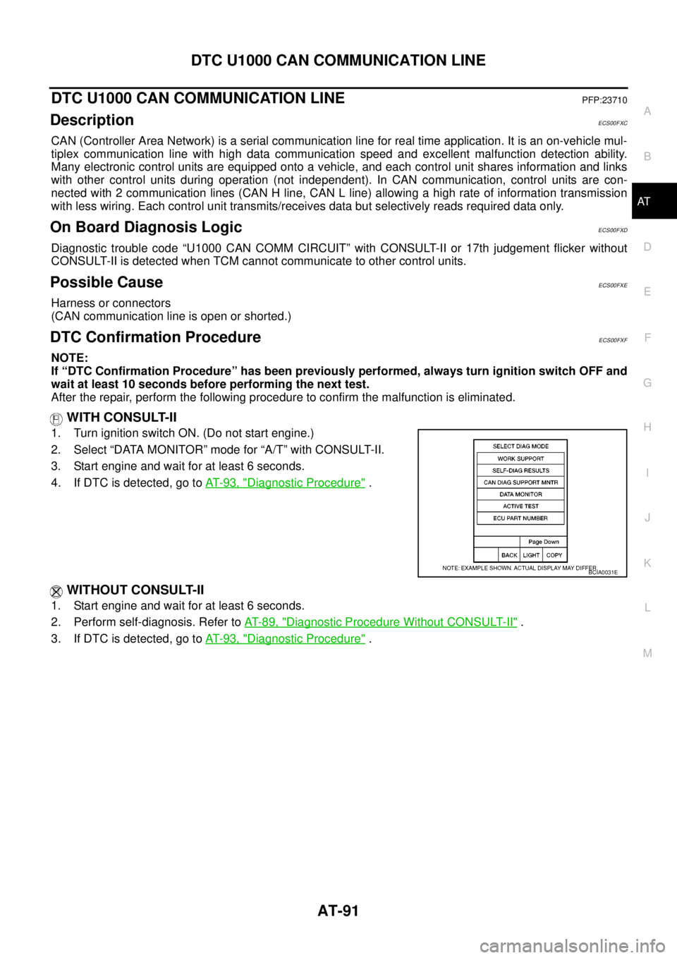
WITH CONSULT-II
1. Turn ignition switch ON. (Do not start engine.)
2. Select “DATA MONITOR” mode for “A/T” with CONSULT-II.
3. Start engine and wait for at least 6 seconds.
4. If DTC is detected, go toAT-93, "
Diagnostic Procedure".
WITHOUT CONSULT-II
1. Start engine and wait for at least 6 seconds.
2. Perform self-diagnosis. Refer toAT-89, "
Diagnostic Procedure Without CONSULT-II".
3. If DTC is detected, go toAT-93, "
Diagnostic Procedure".
BCIA0031E
Page 107 of 3171
DTC P0705 PARK/NEUTRAL POSITION SWITCH
AT-99
D
E
F
G
H
I
J
K
L
MA
B
AT
DTC P0705 PARK/NEUTRAL POSITION SWITCHPFP:32006
DescriptionECS00FXU
lPNP switch includes a transmission range switch.
lThe transmission range switch detects the selector lever position and sends a signal to TCM.
CONSULT-II Reference ValueECS00FXV
On Board Diagnosis LogicECS00FXW
Diagnostic trouble code “P0705 PNP SW/CIRC” with CONSULT-II or 9th judgement flicker without CONSULT-
II is detected under the following conditions.
lWhen TCM does not receive the correct voltage signal from PNP switches 1, 2, 3 and 4 based on the gear
position.
lWhen no other positions but “P” position is detected from “N” position.
Possible CauseECS00FXX
lHarness or connectors
PNP switches 1, 2, 3 and 4 and TCM circuit is open or shorted.
lPNPswitches1,2,3and4
DTC Confirmation ProcedureECS00FXY
CAUTION:
Always drive vehicle at a safe speed.
NOTE:
If “DTC Confirmation Procedure” has been previously performed, always turn ignition switch OFF and
wait at least 10 seconds before performing the next test.
After the repair, perform the following procedure to confirm the malfunction is eliminated.
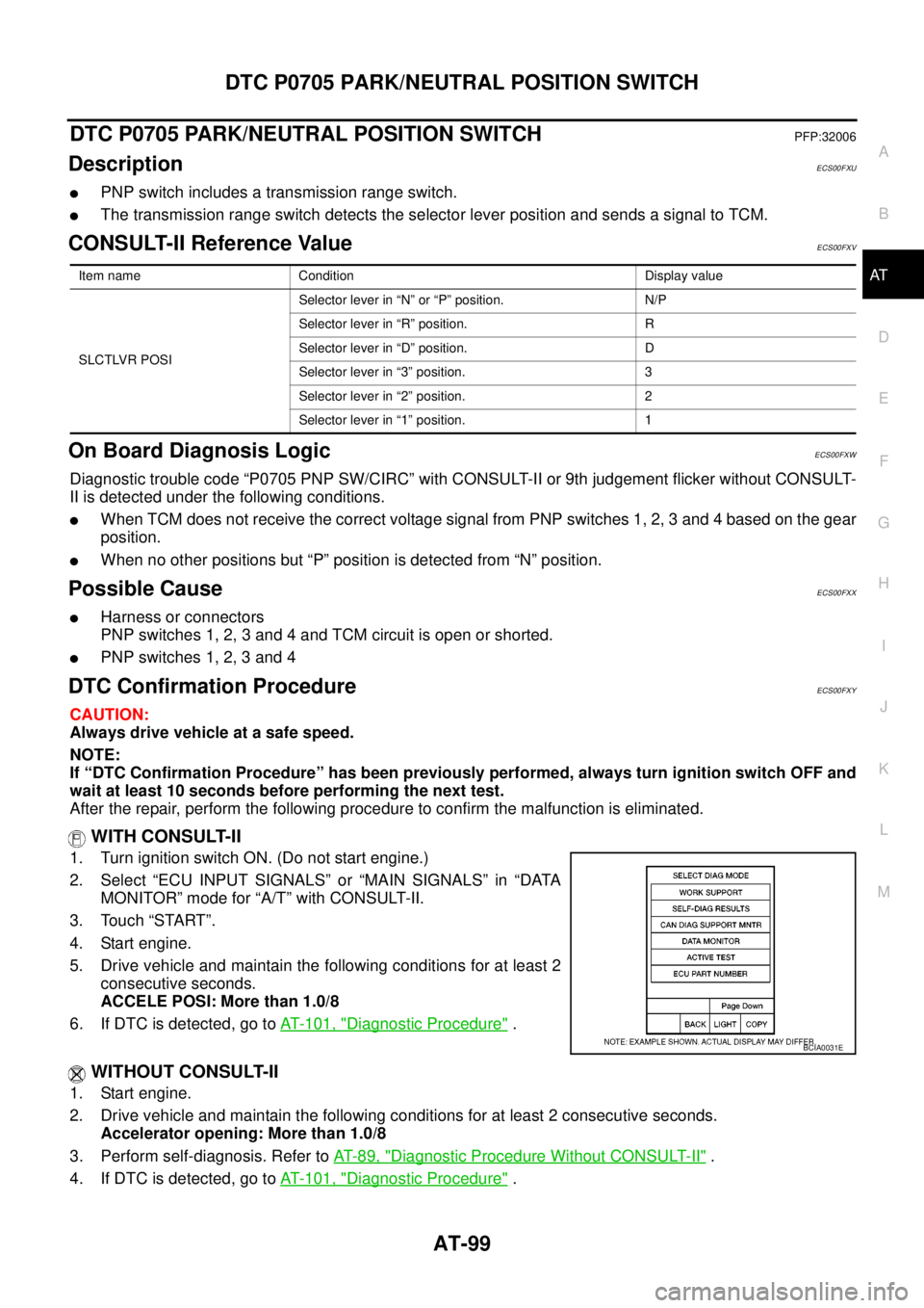
WITH CONSULT-II
1. Turn ignition switch ON. (Do not start engine.)
2. Select “ECU INPUT SIGNALS” or “MAIN SIGNALS” in “DATA
MONITOR” mode for “A/T” with CONSULT-II.
3. Touch “START”.
4. Start engine.
5. Drive vehicle and maintain the following conditions for at least 2
consecutive seconds.
ACCELE POSI: More than 1.0/8
6. If DTC is detected, go toAT- 1 0 1 , "
Diagnostic Procedure".
WITHOUT CONSULT-II
1. Start engine.
2. Drive vehicle and maintain the following conditions for at least 2 consecutive seconds.
Accelerator opening: More than 1.0/8
3. Perform self-diagnosis. Refer toAT-89, "
Diagnostic Procedure Without CONSULT-II".
4. If DTC is detected, go toAT- 1 0 1 , "
Diagnostic Procedure".
Item name Condition Display value
SLCTLVR POSISelector lever in “N” or “P” position. N/P
Selector lever in “R” position. R
Selector lever in “D” position. D
Selector lever in “3” position. 3
Selector lever in “2” position. 2
Selector lever in “1” position. 1
BCIA0031E
Page 189 of 3171
TROUBLE DIAGNOSIS FOR SYMPTOMS
AT-181
D
E
F
G
H
I
J
K
L
MA
B
AT
7.DETECT MALFUNCTIONING ITEM
1. Check control valve with TCM. Refer toAT- 2 1 8 , "
Control Valve With TCM and A/T Fluid Temperature Sen-
sor 2".
2. Disassemble A/T. Refer toAT- 2 6 3 , "
DISASSEMBLY".
3. Check the following.
–Oil pump assembly. Refer toAT- 2 8 1 , "Oil Pump".
–Power train system. Refer toAT- 2 6 3 , "DISASSEMBLY".
–Transmission case. Refer toAT- 2 6 3 , "DISASSEMBLY".
OK or NG
OK >> GO TO 8.
NG >> Repair or replace damaged parts.
8.CHECK A/T FLUID CONDITION
1. Remove oil pan. Refer toAT- 2 1 8 , "
Control Valve With TCM and A/T Fluid Temperature Sensor 2".
2. Check A/T fluid condition. Refer toAT-43, "
A/T Fluid Condition Check".
OK or NG
OK >> GO TO 10.
NG >> GO TO 9.
9.DETECT MALFUNCTIONING ITEM
Check malfunction items. If any items are damaged, repair or replace damaged parts. Refer toAT-53, "
Symp-
tom Chart"(Symptom No.1).
OK or NG
OK >> GO TO 10.
NG >> Repair or replace damaged parts.
10.CHECK SYMPTOM
Check again. Refer toAT-47, "
Check at Idle".
OK or NG
OK >>INSPECTION END
NG >> GO TO 11.
11 .CHECK TCM
1. Check TCM input/output signals. Refer toAT-76, "
TCM Input/Output Signal Reference Values".
2. If NG, recheck A/T assembly harness connector terminals for damage or loose connection with harness
connector.
OK or NG
OK >>INSPECTION END
NG >> Repair or replace damaged parts.
Page 191 of 3171
TROUBLE DIAGNOSIS FOR SYMPTOMS
AT-183
D
E
F
G
H
I
J
K
L
MA
B
AT
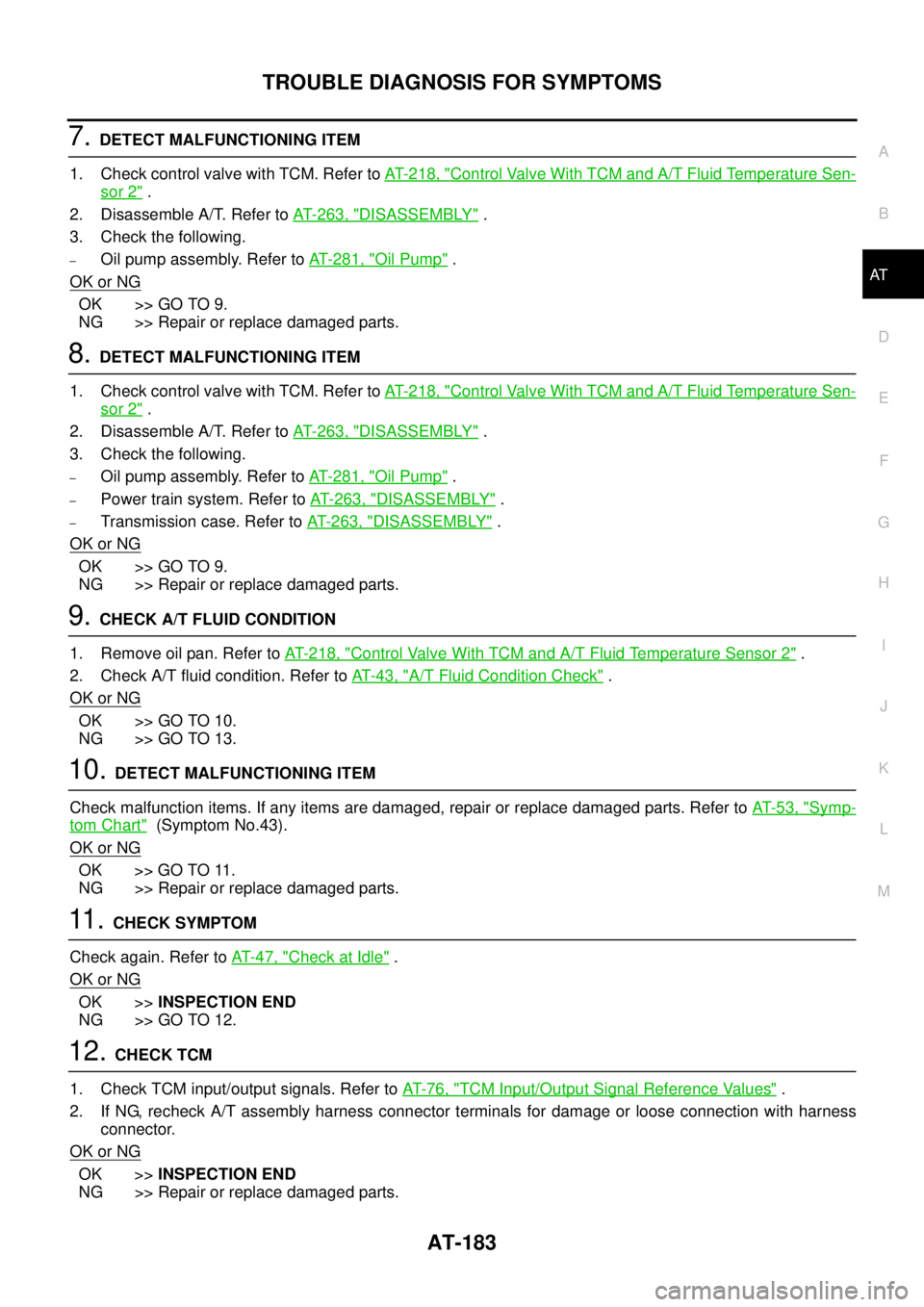
7.DETECT MALFUNCTIONING ITEM
1. Check control valve with TCM. Refer toAT- 2 1 8 , "
Control Valve With TCM and A/T Fluid Temperature Sen-
sor 2".
2. Disassemble A/T. Refer toAT- 2 6 3 , "
DISASSEMBLY".
3. Check the following.
–Oil pump assembly. Refer toAT- 2 8 1 , "Oil Pump".
OK or NG
OK >> GO TO 9.
NG >> Repair or replace damaged parts.
8.DETECT MALFUNCTIONING ITEM
1. Check control valve with TCM. Refer toAT- 2 1 8 , "
Control Valve With TCM and A/T Fluid Temperature Sen-
sor 2".
2. Disassemble A/T. Refer toAT- 2 6 3 , "
DISASSEMBLY".
3. Check the following.
–Oil pump assembly. Refer toAT- 2 8 1 , "Oil Pump".
–Power train system. Refer toAT- 2 6 3 , "DISASSEMBLY".
–Transmission case. Refer toAT- 2 6 3 , "DISASSEMBLY".
OK or NG
OK >> GO TO 9.
NG >> Repair or replace damaged parts.
9.CHECK A/T FLUID CONDITION
1. Remove oil pan. Refer toAT- 2 1 8 , "
Control Valve With TCM and A/T Fluid Temperature Sensor 2".
2. Check A/T fluid condition. Refer toAT-43, "
A/T Fluid Condition Check".
OK or NG
OK >> GO TO 10.
NG >> GO TO 13.
10.DETECT MALFUNCTIONING ITEM
Check malfunction items. If any items are damaged, repair or replace damaged parts. Refer toAT-53, "
Symp-
tom Chart"(Symptom No.43).
OK or NG
OK >> GO TO 11.
NG >> Repair or replace damaged parts.
11 .CHECK SYMPTOM
Check again. Refer toAT-47, "
Check at Idle".
OK or NG
OK >>INSPECTION END
NG >> GO TO 12.
12.CHECK TCM
1. Check TCM input/output signals. Refer toAT-76, "
TCM Input/Output Signal Reference Values".
2. If NG, recheck A/T assembly harness connector terminals for damage or loose connection with harness
connector.
OK or NG
OK >>INSPECTION END
NG >> Repair or replace damaged parts.
Page 193 of 3171
TROUBLE DIAGNOSIS FOR SYMPTOMS
AT-185
D
E
F
G
H
I
J
K
L
MA
B
AT
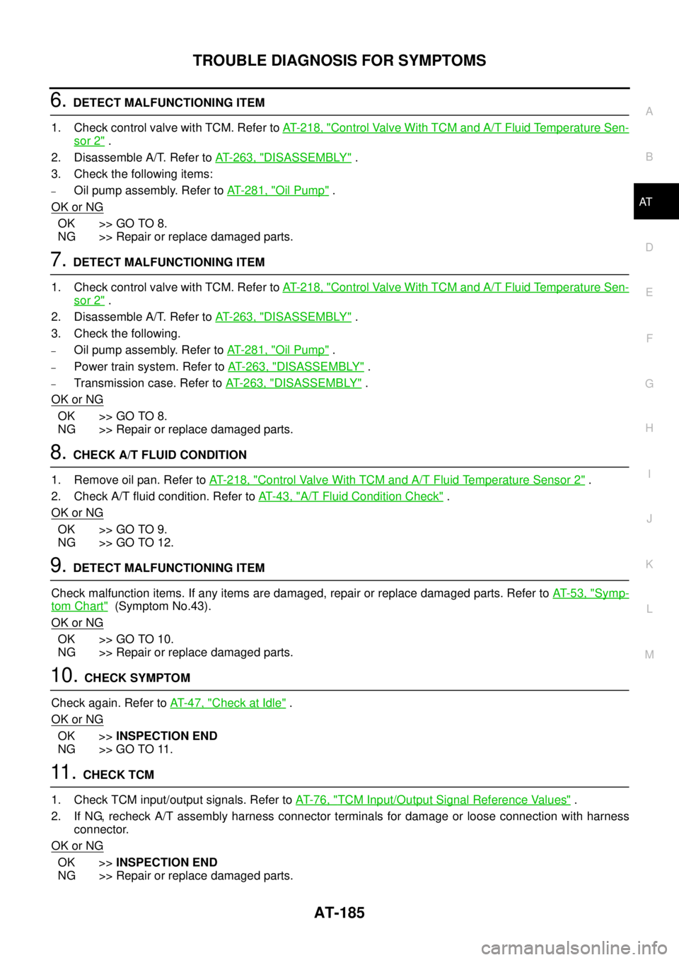
6.DETECT MALFUNCTIONING ITEM
1. Check control valve with TCM. Refer toAT- 2 1 8 , "
Control Valve With TCM and A/T Fluid Temperature Sen-
sor 2".
2. Disassemble A/T. Refer toAT- 2 6 3 , "
DISASSEMBLY".
3. Check the following items:
–Oil pump assembly. Refer toAT- 2 8 1 , "Oil Pump".
OK or NG
OK >> GO TO 8.
NG >> Repair or replace damaged parts.
7.DETECT MALFUNCTIONING ITEM
1. Check control valve with TCM. Refer toAT- 2 1 8 , "
Control Valve With TCM and A/T Fluid Temperature Sen-
sor 2".
2. Disassemble A/T. Refer toAT- 2 6 3 , "
DISASSEMBLY".
3. Check the following.
–Oil pump assembly. Refer toAT- 2 8 1 , "Oil Pump".
–Power train system. Refer toAT- 2 6 3 , "DISASSEMBLY".
–Transmission case. Refer toAT- 2 6 3 , "DISASSEMBLY".
OK or NG
OK >> GO TO 8.
NG >> Repair or replace damaged parts.
8.CHECK A/T FLUID CONDITION
1. Remove oil pan. Refer toAT- 2 1 8 , "
Control Valve With TCM and A/T Fluid Temperature Sensor 2".
2. Check A/T fluid condition. Refer toAT-43, "
A/T Fluid Condition Check".
OK or NG
OK >> GO TO 9.
NG >> GO TO 12.
9.DETECT MALFUNCTIONING ITEM
Check malfunction items. If any items are damaged, repair or replace damaged parts. Refer toAT-53, "
Symp-
tom Chart"(Symptom No.43).
OK or NG
OK >> GO TO 10.
NG >> Repair or replace damaged parts.
10.CHECK SYMPTOM
Check again. Refer toAT-47, "
Check at Idle".
OK or NG
OK >>INSPECTION END
NG >> GO TO 11.
11 .CHECK TCM
1. Check TCM input/output signals. Refer toAT-76, "
TCM Input/Output Signal Reference Values".
2. If NG, recheck A/T assembly harness connector terminals for damage or loose connection with harness
connector.
OK or NG
OK >>INSPECTION END
NG >> Repair or replace damaged parts.
Page 195 of 3171
TROUBLE DIAGNOSIS FOR SYMPTOMS
AT-187
D
E
F
G
H
I
J
K
L
MA
B
AT
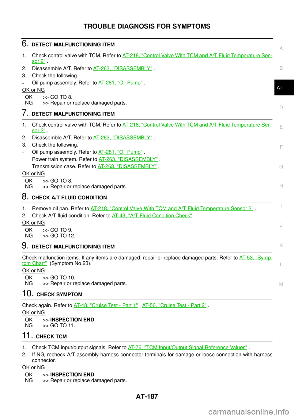
6.DETECT MALFUNCTIONING ITEM
1. Check control valve with TCM. Refer toAT- 2 1 8 , "
Control Valve With TCM and A/T Fluid Temperature Sen-
sor 2".
2. Disassemble A/T. Refer toAT- 2 6 3 , "
DISASSEMBLY".
3. Check the following.
–Oil pump assembly. Refer toAT- 2 8 1 , "Oil Pump".
OK or NG
OK >> GO TO 8.
NG >> Repair or replace damaged parts.
7.DETECT MALFUNCTIONING ITEM
1. Check control valve with TCM. Refer toAT- 2 1 8 , "
Control Valve With TCM and A/T Fluid Temperature Sen-
sor 2".
2. Disassemble A/T. Refer toAT- 2 6 3 , "
DISASSEMBLY".
3. Check the following.
–Oil pump assembly. Refer toAT- 2 8 1 , "Oil Pump".
–Power train system. Refer toAT- 2 6 3 , "DISASSEMBLY".
–Transmission case. Refer toAT- 2 6 3 , "DISASSEMBLY".
OK or NG
OK >> GO TO 8.
NG >> Repair or replace damaged parts.
8.CHECK A/T FLUID CONDITION
1. Remove oil pan. Refer toAT- 2 1 8 , "
Control Valve With TCM and A/T Fluid Temperature Sensor 2".
2. Check A/T fluid condition. Refer toAT-43, "
A/T Fluid Condition Check".
OK or NG
OK >> GO TO 9.
NG >> GO TO 12.
9.DETECT MALFUNCTIONING ITEM
Check malfunction items. If any items are damaged, repair or replace damaged parts. Refer toAT-53, "
Symp-
tom Chart"(Symptom No.23).
OK or NG
OK >> GO TO 10.
NG >> Repair or replace damaged parts.
10.CHECK SYMPTOM
Check again. Refer toAT-48, "
Cruise Test - Part 1",AT-50, "Cruise Test - Part 2".
OK or NG
OK >>INSPECTION END
NG >> GO TO 11.
11 .CHECK TCM
1. Check TCM input/output signals. Refer toAT-76, "
TCM Input/Output Signal Reference Values".
2. If NG, recheck A/T assembly harness connector terminals for damage or loose connection with harness
connector.
OK or NG
OK >>INSPECTION END
NG >> Repair or replace damaged parts.