2005 NISSAN NAVARA brake sensor
[x] Cancel search: brake sensorPage 1037 of 3171
![NISSAN NAVARA 2005 Repair Workshop Manual TROUBLE DIAGNOSIS
EC-57
C
D
E
F
G
H
I
J
K
L
MA
EC71 LTurbocharger boost sensor
ground[Ignition switch ON]Approximately 0.3V
72 BRRefrigerant pressure sensor
ground[Engine is running]
lWarm-up conditio NISSAN NAVARA 2005 Repair Workshop Manual TROUBLE DIAGNOSIS
EC-57
C
D
E
F
G
H
I
J
K
L
MA
EC71 LTurbocharger boost sensor
ground[Ignition switch ON]Approximately 0.3V
72 BRRefrigerant pressure sensor
ground[Engine is running]
lWarm-up conditio](/manual-img/5/57362/w960_57362-1036.png)
TROUBLE DIAGNOSIS
EC-57
C
D
E
F
G
H
I
J
K
L
MA
EC71 LTurbocharger boost sensor
ground[Ignition switch ON]Approximately 0.3V
72 BRRefrigerant pressure sensor
ground[Engine is running]
lWarm-up condition
lIdle speedApproximately 0.3V
73 B Mass air flow sensor ground[Ignition switch ON]Approximately 0.3V
74 RIntake air temperature sen-
sor ground[Ignition switch ON]Approximately 0.3V
82 WAccelerator pedal position
sensor 1 power supply[Ignition switch ON]Approximately 5.3V
83 RAccelerator pedal position
sensor 1[Ignition switch ON]
lEngine: Stopped
lAccelerator pedal: Fully released0.95 - 1.17V
[Ignition switch ON]
lEngine: Stopped
lAccelerator pedal: Fully depressedMore than 4.6V
84 BAccelerator pedal position
sensor 1 ground[Ignition switch ON]Approximately 0.3V
85 —Sensor ground
(Accelerator pedal position
sensor shield circuit)[Ignition switch ON]Approximately 0.3V
87 P CAN communication line[Ignition switch ON]Approximately 2.0 - 2.6V
Output voltage varies with the
communication status.
89 SB Data link connector[Ignition switch ON]
lCONSULT-II: DisconnectedApproximately 0V - Battery volt-
age (11 - 14V)
90 WAccelerator pedal position
sensor 2 power supply[Ignition switch ON]Approximately 5.3V
91 RAccelerator pedal position
sensor 2[Ignition switch ON]
lEngine: Stopped
lAccelerator pedal: Fully released0.58 - 0.78V
[Ignition switch ON]
lEngine: Stopped
lAccelerator pedal: Fully depressedMore than 2.3V
92 BAccelerator pedal position
sensor 2 ground[Ignition switch ON]Approximately 0.3V
95 L CAN communication line[Ignition switch ON]Approximately 2.6 - 3.2V
Output voltage varies with the
communication status.
99 V Start signal[Ignition switch ON]Approximately 0.3V
[Ignition switch START]BATTERY VOLTAGE
(11 - 14V)
100 V Stop lamp switch[Ignition switch OFF]
lBrake pedal: Fully releasedApproximately 0V
[Ignition switch OFF]
lBrake pedal: Slightly depressedBATTERY VOLTAGE
(11 - 14V) TERMI-
NAL
NO.WIRE
COLORITEM CONDITIONDATA
(DC Voltage and Pulse Signal)
Page 1040 of 3171

EC-60
TROUBLE DIAGNOSIS
ENGINE CONTROL COMPONENT PARTS/CONTROL SYSTEMS APPLICATION
X: ApplicableItemDIAGNOSTIC TEST MODE
SELF-DIAG RESULTS
DATA MON-
ITORACTIVE
TEST
DTCFREEZE
FRAME
DATA
ENGINE CONTROL COMPONENT PARTS
INPUTCrankshaft position sensor´´´
Camshaft position sensor´
Engine coolant temperature sensor´´´´
Vehicle speed signal´´´
Fuel pump temperature sensor´´
Accelerator pedal position sensor 1´´
Accelerator pedal position sensor 2´´
Fuel rail pressure sensor´´
Mass air flow sensor´´
Intake air temperature sensor´
Turbocharger boost sensor´´´
Refrigerant pressure sensor´
Battery voltage´´
Park/neutral position (PNP) switch´
Heat up switch´
Stop lamp switch´´
Barometric pressure sensor (built-into ECM)´´
ASCD steering switch´´
ASCD brake switch´´
ASCD clutch switch´´
OUTPUTFuel pump´´´
Fuel injector´´´
Glow relay´´
Cooling fan relay´´´
Turbocharger boost control solenoid valve´
Intake air control valve control solenoid valve
EGR volume control valve´´
Page 1043 of 3171
![NISSAN NAVARA 2005 Repair Workshop Manual TROUBLE DIAGNOSIS
EC-63
C
D
E
F
G
H
I
J
K
L
MA
ECACT CR PRESS [MPa]´´
lThe Fuel rail pressure (determined by
the signal voltage of the fuel rail pres-
sure sensor) is displayed.
BATTERY VOLT [V]´´ NISSAN NAVARA 2005 Repair Workshop Manual TROUBLE DIAGNOSIS
EC-63
C
D
E
F
G
H
I
J
K
L
MA
ECACT CR PRESS [MPa]´´
lThe Fuel rail pressure (determined by
the signal voltage of the fuel rail pres-
sure sensor) is displayed.
BATTERY VOLT [V]´´](/manual-img/5/57362/w960_57362-1042.png)
TROUBLE DIAGNOSIS
EC-63
C
D
E
F
G
H
I
J
K
L
MA
ECACT CR PRESS [MPa]´´
lThe Fuel rail pressure (determined by
the signal voltage of the fuel rail pres-
sure sensor) is displayed.
BATTERY VOLT [V]´´
lThe power supply voltage of ECM is
displayed.
P/N POSI SW [ON/OFF]´´
lIndicates [ON/OFF] condition from the
park/neutral position switch signal.
START SIGNAL [ON/OFF]´´
lIndicates [ON/OFF] condition from the
starter signal.
AIR COND SIG [ON/OFF]´´
lIndicates [ON/OFF] condition of the air
conditioner switch as determined by
the air conditioner signal.
BRAKE SW [ON/OFF]´´
lIndicates [ON/OFF] condition from the
stop lamp switch signal.
BRAKE SW2 [ON/OFF]´´
lIndicates [ON/OFF] condition from the
ASCD brake switch and ASCD clutch
switch signal.
IGN SW [ON/OFF]´´
lIndicates [ON/OFF] condition from
ignition switch signal.
WARM UP SW [ON/OFF]´
lIndicates [ON/OFF] condition from
heat up switch signal.
MAS AIR/FL SE [V]´´
lThe signal voltage of the mass air flow
sensor is displayed.This signal is converted by ECM inter-
nally. Thus, these differ from ECM termi-
nals voltage.
MAIN INJ WID [msec]´
lIndicates the actual fuel injection pulse
width compensated by ECM according
to the input signals.
PUMP CURRENT [mA]´
lIndicates the fuel pump power supply
current from the ECM.
GLOW RLY [ON/OFF]´
lThe glow relay control condition
(determined by ECM according to the
input signal) is displayed.
COOLING FAN
[LOW/HI/OFF]´
lIndicates the control condition of the
cooling fans (determined by ECM
according to the input signal).
LOW ... Operates at low speed
HI ... Operates at high speed
OFF ... Stopped
EGR VOL CON/V [step]´
lIndicates the EGR volume control
value computed by the ECM accord-
ing to the input signals.
lThe opening becomes larger as the
value increases.
INT/A VOLUME [mg/]
lThe intake air volume computed from
the mass air flow sensor signal is dis-
played.
BARO SEN [kPa]´´
lThe barometric pressure (determined
by the signal voltage from the absolute
pressure sensor built into the ECM) is
displayed. MONITOR ITEMECM
INPUT
SIG-
NALMAIN
SIG-
NALSCONDITION SPECIFICATION
Page 1335 of 3171

AUTOMATIC SPEED CONTROL DEVICE (ASCD)
EC-355
C
D
E
F
G
H
I
J
K
L
MA
EC
AUTOMATIC SPEED CONTROL DEVICE (ASCD)PFP:18930
System DescriptionEBS01KN2
INPUT/OUTPUT SIGNAL CHART
*: This signal is sent to the ECM through CAN communication line.
BASIC ASCD SYSTEM
Refer to Owner's Manual for ASCD operating instructions.
Automatic Speed Control Device (ASCD) allows a driver to keep vehicle at predetermined constant speed
without depressing accelerator pedal. Driver can set vehicle speed in advance between approximately 40 km/
h(25MPH)and185km/h(115MPH).
ECM controls fuel injection value to regulate engine speed.
Operation status of ASCD is indicated by CRUISE indicator and SET indicator in combination meter. If any
malfunction occurs in ASCD system, it automatically deactivates control.
SET OPERATION
Press ASCD MAIN switch. (The CRUISE indicator in combination meter illuminates.)
When vehicle speed reaches a desired speed between approximately 40 km/h (25 MPH) and 185 km/h (115
MPH), press SET/COST switch. (Then SET indicator in combination meter illuminates.)
ACCEL OPERATION
If the RESUME/ACCELERATE switch is depressed during cruise control driving, increase the vehicle speed
until the switch is released or vehicle speed reaches maximum speed controlled by the system.
And then ASCD will keep the new set speed.
CANCEL OPERATION
When any of following conditions exist, cruise operation will be canceled.
lCANCEL switch is depressed
lMore than 2 switches at ASCD steering switch are depressed at the same time (Set speed will be cleared)
lBrake pedal is depressed
lClutch pedal is depressed or gear position is changed to the neutral position (M/T models)
lSelector lever is changed to N, P, R position (A/T models)
lVehicle speed decreased to 13 km/h (8 MPH) lower than the set speed
When the ECM detects any of the following conditions, the ECM will cancel the cruise operation and inform
the driver by blinking indicator lamp.
lMalfunction for some self-diagnoses regarding ASCD control: SET lamp will blink quickly.
If MAIN switch is turned to OFF during ASCD is activated, all of ASCD operations will be canceled and vehicle
speed memory will be erased.
COAST OPERATION
When the SET/COAST switch is depressed during cruise control driving, decrease vehicle set speed until the
switch is released. And then ASCD will keep the new set speed.
RESUME OPERATION
When the RESUME/ACCELERATE switch is depressed after cancel operation other than depressing MAIN
switch is performed, vehicle speed will return to last set speed. To resume vehicle set speed, vehicle condition
must meet following conditions.
Sensor Input signal to ECM ECM function Actuator
ASCD brake switch Brake pedal operation
ASCD vehicle speed control Fuel injector and Fuel pump Stop lamp switch Brake pedal operation
ASCD clutch switch (M/T) Clutch pedal operation
ASCD steering switch ASCD steering switch operation
Park/Neutral position (PNP)
switchGear position
Combination meter* Vehicle speed
TCM* Powertrain revolution
Page 1480 of 3171

EM-98
CYLINDER HEAD
lBefore installing, remove carbon depositing on mounting hole of glow plug with a reamer.
6. Install engine coolant temperature sensor.
7. Install in the reverse order of removal.
INSPECTION AFTER INSTALLATION
Inspection for Leaks
The following are procedures for checking fluids leak, lubricates leak and exhaust gases leak.
lBefore starting engine, check oil/fluid levels including engine coolant and engine oil. If less than required
quantity, fill to the specified level. Refer toMA-14, "
RECOMMENDED FLUIDS AND LUBRICANTS".
lUse procedure below to check for fuel leakage.
–Turn ignition switch “ON” (with engine stopped). With fuel pressure applied to fuel piping, check for fuel
leakage at connection points.
–Start engine. With engine speed increased, check again for fuel leakage at connection points.
lRun engine to check for unusual noise and vibration.
lWarm up engine thoroughly to make sure there is no leakage of fuel, exhaust gases, or any oil/fluids
including engine oil and engine coolant.
lBleed air from lines and hoses of applicable lines, such as in cooling system.
lAfter cooling down engine, again check oil/fluid levels including engine oil and engine coolant. Refill to the
specified level, if necessary.
Summary of the inspection items:
*1: Transmission/transaxle/CVT fluid, power steering fluid, brake fluid, etc.
*2: Check engine oil level 10 minutes after engine stopped.Item Before starting engine Engine running After engine stopped
Engine coolant Level Leakage Level
Engine oil Level Leakage Level (*2)
Other oils and fluid (*1) Level Leakage Level
Fuel Leakage Leakage Leakage
Exhaust gases — Leakage —
Page 1537 of 3171

WHEEL HUB
FAX-5
C
E
F
G
H
I
J
K
L
MA
B
FA X
WHEEL HUBPFP:43202
On-Vehicle Inspection and ServiceEDS003I7
Make sure the mounting conditions (looseness, backlash) of each component and component status (wear,
damage) are normal.
WHEEL BEARING INSPECTION
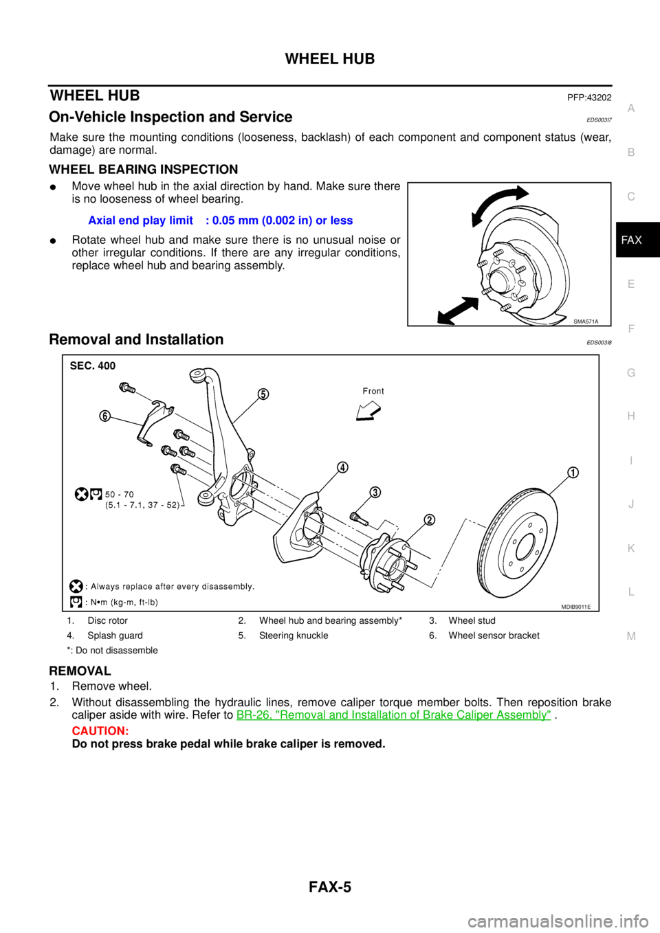
lMove wheel hub in the axial direction by hand. Make sure there
is no looseness of wheel bearing.
lRotate wheel hub and make sure there is no unusual noise or
other irregular conditions. If there are any irregular conditions,
replace wheel hub and bearing assembly.
Removal and InstallationEDS003I8
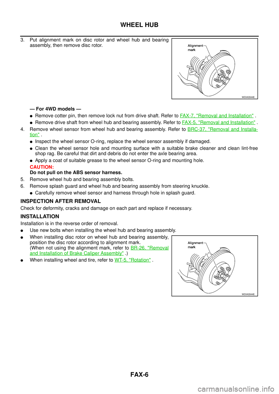
REMOVAL
1. Remove wheel.
2. Without disassembling the hydraulic lines, remove caliper torque member bolts. Then reposition brake
caliper aside with wire. Refer toBR-26, "
Removal and Installation of Brake Caliper Assembly".
CAUTION:
Do not press brake pedal while brake caliper is removed.Axial end play limit : 0.05 mm (0.002 in) or less
SMA571A
1. Disc rotor 2. Wheel hub and bearing assembly* 3. Wheel stud
4. Splash guard 5. Steering knuckle 6. Wheel sensor bracket
*: Do not disassemble
MDIB9011E
Page 1538 of 3171

FAX-6
WHEEL HUB
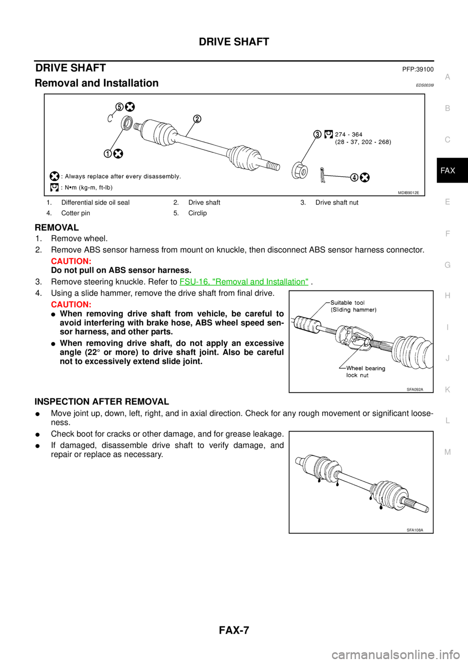
3. Put alignment mark on disc rotor and wheel hub and bearing
assembly, then remove disc rotor.
— For 4WD models —
lRemove cotter pin, then remove lock nut from drive shaft. Refer toFA X - 7 , "Removal and Installation".
lRemove drive shaft from wheel hub and bearing assembly. Refer toFAX-5, "Removal and Installation".
4. Remove wheel sensor from wheel hub and bearing assembly. Refer toBRC-37, "
Removal and Installa-
tion".
lInspect the wheel sensor O-ring, replace the wheel sensor assembly if damaged.
lClean the wheel sensor hole and mounting surface with a suitable brake cleaner and clean lint-free
shop rag. Be careful that dirt and debris do not enter the axle bearing area.
lApply a coat of suitable grease to the wheel sensor O-ring and mounting hole.
CAUTION:
Do not pull on the ABS sensor harness.
5. Remove wheel hub and bearing assembly bolts.
6. Remove splash guard and wheel hub and bearing assembly from steering knuckle.
lCarefully remove wheel sensor and harness through hole in splash guard.
INSPECTION AFTER REMOVAL
Check for deformity, cracks and damage on each part and replace if necessary.
INSTALLATION
Installation is in the reverse order of removal.
lUse new bolts when installing the wheel hub and bearing assembly.
lWhen installing disc rotor on wheel hub and bearing assembly,
position the disc rotor according to alignment mark.
(When not using the alignment mark, refer toBR-26, "
Removal
and Installation of Brake Caliper Assembly".)
lWhen installing wheel and tire, refer toWT-5, "Rotation".
WDIA0044E
WDIA0044E
Page 1539 of 3171

DRIVE SHAFT
FAX-7
C
E
F
G
H
I
J
K
L
MA
B
FA X
DRIVE SHAFTPFP:39100
Removal and InstallationEDS003I9
REMOVAL
1. Remove wheel.
2. Remove ABS sensor harness from mount on knuckle, then disconnect ABS sensor harness connector.
CAUTION:
Do not pull on ABS sensor harness.
3. Remove steering knuckle. Refer toFSU-16, "
Removal and Installation".
4. Using a slide hammer, remove the drive shaft from final drive.
CAUTION:
lWhen removing drive shaft from vehicle, be careful to
avoid interfering with brake hose, ABS wheel speed sen-
sor harness, and other parts.
lWhen removing drive shaft, do not apply an excessive
angle (22°or more) to drive shaft joint. Also be careful
not to excessively extend slide joint.
INSPECTION AFTER REMOVAL
lMove joint up, down, left, right, and in axial direction. Check for any rough movement or significant loose-
ness.
lCheck boot for cracks or other damage, and for grease leakage.
lIf damaged, disassemble drive shaft to verify damage, and
repair or replace as necessary.
1. Differential side oil seal 2. Drive shaft 3. Drive shaft nut
4. Cotter pin 5. Circlip
MDIB9012E
SFA092A
SFA108A