2005 NISSAN NAVARA brake sensor
[x] Cancel search: brake sensorPage 857 of 3171
![NISSAN NAVARA 2005 Repair Workshop Manual TROUBLE DIAGNOSIS
BRC-35
[ABS]
C
D
E
G
H
I
J
K
L
MA
B
BRC
Symptom 4: ABS Function Does Not OperateEFS005UB
CAUTION:
ABS does not operate when speed is 10 km/h (6 MPH) or lower.
1.CHECK ABS WARNING LAM NISSAN NAVARA 2005 Repair Workshop Manual TROUBLE DIAGNOSIS
BRC-35
[ABS]
C
D
E
G
H
I
J
K
L
MA
B
BRC
Symptom 4: ABS Function Does Not OperateEFS005UB
CAUTION:
ABS does not operate when speed is 10 km/h (6 MPH) or lower.
1.CHECK ABS WARNING LAM](/manual-img/5/57362/w960_57362-856.png)
TROUBLE DIAGNOSIS
BRC-35
[ABS]
C
D
E
G
H
I
J
K
L
MA
B
BRC
Symptom 4: ABS Function Does Not OperateEFS005UB
CAUTION:
ABS does not operate when speed is 10 km/h (6 MPH) or lower.
1.CHECK ABS WARNING LAMP DISPLAY
Make sure that the ABS warning lamp is turned off after the ignition switch is turned ON or when driving.
OK or NG
OK >> GO TO procedure 3 “CHECK WHEEL SENSOR AND SENSOR ROTOR” of symptom1. Refer to
BRC-33, "
Symptom 1: Excessive ABS Function Operation Frequency".
NG >> Perform self-diagnosis. Refer toBRC-18, "
Self-Diagnosis".
Symptom 5: Pedal Vibration or ABS Operation Sound OccursEFS005UC
CAUTION:
Under the following conditions, ABS is activated and vibration is felt when brake pedal is lightly
depressed (just place a foot on it). However, this is normal.
lWhen shifting gears
lWhen driving on slippery road
lDuring cornering at high speed
lWhen passing over bumps or grooves [at approximately 50 mm (1.97 in) or more]
lWhen pulling away just after starting engine [at approximately 10 km/h (6 MPH) or more]
1.SYMPTOM CHECK 1
Check if there is pedal vibration or operation noise when the engine is started.
Do symptoms occur?
YES >> GO TO 2.
NO >> Perform self-diagnosis. Refer toBRC-18, "
Self-Diagnosis".
2.SYMPTOM CHECK 2
Check symptoms when electrical component (headlamps, etc.) switches are operated.
Do symptoms occur?
YES >> Check if there is a radio, antenna, antenna lead wire, or wiring close to the control unit. If there is,
move it farther away.
NO >> GO TO procedure 3²CHECK WHEEL SENSOR AND SENSOR ROTOR²of symptom 1. Refer to
BRC-33, "
Symptom 1: Excessive ABS Function Operation Frequency".
Symptom 6: ABS Warning Lamp Indication Is Not NormalEFS005UD
NOTE:
Lighting condition of ABS warning lamp refer toBRC-24, "
BASIC INSPECTION 3 ABS WARNING LAMP AND
BRAKE WARNING LAMP INSPECTION".
1.CHECK COMBINATION METER INDICATION
Check the combination meter indication and operation. Refer toDI-13, "
Self-Diagnosis Mode of Combination
Meter".
OK or NG
OK >> GO TO 2.
NG >> Combination meter is malfunctioning. Check combination meter. Refer toDI-4, "
COMBINATION
METERS".
Page 983 of 3171

EC-3
C
D
E
F
G
H
I
J
K
L
M
ECA Component Inspection ......................................... 158
Removal and Installation ...................................... 158
DTC P0335 CKP SENSOR ..................................... 159
Description ........................................................... 159
CONSULT-II Reference Value in Data Monitor Mode
. 159
ECM Terminals and Reference Value .................. 159
On Board Diagnosis Logic ................................... 160
DTC Confirmation Procedure ............................... 160
Wiring Diagram .................................................... 161
Diagnostic Procedure ........................................... 162
Component Inspection ......................................... 164
Removal and Installation ...................................... 164
DTC P0336 CKP SENSOR ..................................... 165
Description ........................................................... 165
CONSULT-II Reference Value in Data Monitor Mode
. 165
ECM Terminals and Reference Value .................. 165
On Board Diagnosis Logic ................................... 166
DTC Confirmation Procedure ............................... 166
Wiring Diagram .................................................... 167
Diagnostic Procedure ........................................... 168
Component Inspection ......................................... 170
Removal and Installation ...................................... 170
DTC P0340 CMP SENSOR .................................... 171
Description ........................................................... 171
ECM Terminals and Reference Value .................. 171
On Board Diagnosis Logic ................................... 172
DTC Confirmation Procedure ............................... 172
Wiring Diagram .................................................... 173
Diagnostic Procedure ........................................... 174
Component Inspection ......................................... 175
Removal and Installation ...................................... 176
DTC P0341 CMP SENSOR .................................... 177
Description ........................................................... 177
ECM Terminals and Reference Value .................. 177
On Board Diagnosis Logic ................................... 178
DTC Confirmation Procedure ............................... 178
Wiring Diagram .................................................... 179
Diagnostic Procedure ........................................... 180
Component Inspection ......................................... 182
Removal and Installation ...................................... 182
DTC P0501 ASCD VEHICLE SPEED SENSOR .... 183
Component Description ........................................ 183
On Board Diagnosis Logic ................................... 183
DTC Confirmation Procedure ............................... 183
Diagnostic Procedure ........................................... 184
DTC P0502 ASCD VEHICLE SPEED SENSOR .... 185
Component Description ........................................ 185
On Board Diagnosis Logic ................................... 185
DTC Confirmation Procedure ............................... 185
Diagnostic Procedure ........................................... 186
DTC P0503 ASCD VEHICLE SPEED SENSOR .... 187
Component Description ........................................ 187
On Board Diagnosis Logic ................................... 187
DTC Confirmation Procedure ............................... 187
Diagnostic Procedure ........................................... 188
DTC P0504 ASCD BRAKE SWITCH ..................... 189
Component Description ........................................ 189CONSULT-II Reference Value in Data Monitor Mode
.189
ECM Terminals and Reference Value ...................189
On Board Diagnosis Logic ....................................190
DTC confirmation Procedure ................................190
Wiring Diagram .....................................................192
Diagnostic Procedure ...........................................193
Component Inspection ..........................................202
DTC P0563 BATTERY VOLTAGE ..........................203
On Board Diagnosis Logic ....................................203
DTC Confirmation Procedure ...............................203
Diagnostic Procedure ...........................................203
DTC P0580, P0581 ASCD STEERING SWITCH ....206
Component Description ........................................206
CONSULT-II Reference Value in Data Monitor Mode
.206
ECM Terminals and Reference Value ...................206
On Board Diagnosis Logic ....................................207
DTC Confirmation Procedure ...............................207
Wiring Diagram .....................................................208
Diagnostic Procedure ...........................................209
Component Inspection ..........................................212
DTC P0605 ECM .....................................................213
Description ............................................................213
On Board Diagnosis Logic ....................................213
DTC Confirmation Procedure ...............................213
Diagnostic Procedure ...........................................214
DTC P0606 ECM .....................................................215
Description ............................................................215
On Board Diagnosis Logic ....................................215
DTC Confirmation Procedure ...............................215
Diagnostic Procedure ...........................................216
DTC P0628, P0629 FUEL PUMP ............................217
Description ............................................................217
CONSULT-II Reference Value in Data Monitor Mode
.217
ECM Terminals and Reference Value ...................217
On Board Diagnosis Logic ....................................218
DTC Confirmation Procedure ...............................218
Wiring Diagram .....................................................219
Diagnostic Procedure ...........................................220
Component Inspection ..........................................221
Removal and Installation ......................................221
DTC P0642, P0643 SENSOR POWER SUPPLY ....222
ECM Terminals and Reference Value ...................222
On Board Diagnosis Logic ....................................222
DTC Confirmation Procedure ...............................223
Wiring Diagram .....................................................224
Diagnostic Procedure ...........................................225
DTC P0652, P0653 SENSOR POWER SUPPLY ....227
ECM Terminals and Reference Value ...................227
On Board Diagnosis Logic ....................................228
DTC Confirmation Procedure ...............................228
Wiring Diagram .....................................................229
Diagnostic Procedure ...........................................230
DTC P0686 ECM RELAY ........................................232
ECM Terminals and Reference valve ...................232
On Board Diagnosis Logic ....................................232
DTC Confirmation Procedure ...............................232
Page 985 of 3171

EC-5
C
D
E
F
G
H
I
J
K
L
M
ECA . 303
ECM Terminals and Reference Value .................. 303
Wiring Diagram .................................................... 304
Diagnostic Procedure ........................................... 305
Component Inspection ......................................... 307
Removal and Installation ...................................... 308
TC BOOST CONTROL SOLENOID VALVE ........... 309
Description ........................................................... 309
ECM Terminals and Reference Value .................. 310
Wiring Diagram ..................................................... 311
Diagnostic Procedure ........................................... 312
Component Inspection ......................................... 313
Removal and Installation ...................................... 313
INTAKE AIR CONTROL VALVE CONTROL SOLE-
NOID VALVE ........................................................... 314
Description ........................................................... 314
ECM Terminals and Reference Value .................. 314
Wiring Diagram .................................................... 315
Diagnostic Procedure ........................................... 316
Component Inspection ......................................... 318
HEAT UP SWITCH .................................................. 319
Description ........................................................... 319
CONSULT-II Reference Value in Data Monitor Mode
. 319
ECM Terminals and Reference Value .................. 319
Wiring Diagram .................................................... 320
Diagnostic Procedure ........................................... 321
Component Inspection ......................................... 324
REFRIGERANT PRESSURE SENSOR ................. 325
Component Description ........................................ 325
ECM Terminals and Reference Value .................. 325
Wiring Diagram .................................................... 326
Diagnostic Procedure ........................................... 327
Removal and Installation ...................................... 329
BRAKE SWITCH .................................................... 330
Description ........................................................... 330
CONSULT-II Reference Value in Data Monitor Mode.330
ECM Terminals and Reference Value ...................330
Wiring Diagram .....................................................331
Diagnostic Procedure ...........................................332
Component Inspection ..........................................341
PNP SWITCH ..........................................................342
Description ............................................................342
CONSULT-II Reference Value in Data Monitor Mode
.342
ECM Terminals and Reference Value ...................342
Wiring Diagram .....................................................343
Diagnostic Procedure ...........................................344
START SIGNAL ......................................................348
Wiring Diagram .....................................................348
Diagnostic Procedure ...........................................349
ASCD INDICATOR ..................................................351
Component Description ........................................351
Wiring Diagram .....................................................352
Diagnostic Procedure ...........................................353
MI & DATA LINK CONNECTORS ...........................354
Wiring Diagram .....................................................354
AUTOMATIC SPEED CONTROL DEVICE (ASCD). 355
System Description ...............................................355
Component Description ........................................356
SERVICE DATA AND SPECIFICATIONS (SDS) ....357
General Specifications ..........................................357
Mass Air Flow Sensor ...........................................357
Intake Air Temperature Sensor .............................357
Engine Coolant Temperature Sensor ...................357
Fuel Rail Pressure Sensor ....................................357
Fuel Injector ..........................................................357
Glow Plug .............................................................357
EGR Volume Control Valve ..................................357
Crankshaft Position Sensor ..................................357
Camshaft Position Sensor ....................................357
Fuel Pump ............................................................358
Page 987 of 3171

INDEX FOR DTC
EC-7
C
D
E
F
G
H
I
J
K
L
MA
EC
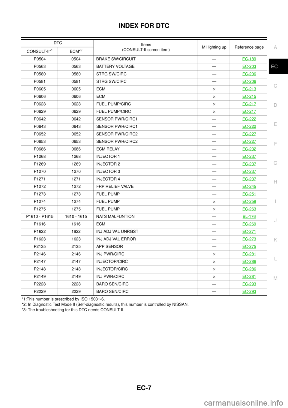
*1:This number is prescribed by ISO 15031-6.
*2: In Diagnostic Test Mode II (Self-diagnostic results), this number is controlled by NISSAN.
*3: The troubleshooting for this DTC needs CONSULT-II.P0504 0504 BRAKE SW/CIRCUIT —EC-189
P0563 0563 BATTERY VOLTAGE —EC-203
P0580 0580 STRG SW/CIRC —EC-206
P0581 0581 STRG SW/CIRC —EC-206
P0605 0605 ECM´EC-213
P0606 0606 ECM´EC-215
P0628 0628 FUEL PUMP/CIRC´EC-217
P0629 0629 FUEL PUMP/CIRC´EC-217
P0642 0642 SENSOR PWR/CIRC1 —EC-222
P0643 0643 SENSOR PWR/CIRC1 —EC-222
P0652 0652 SENSOR PWR/CIRC2 —EC-227
P0653 0653 SENSOR PWR/CIRC2 —EC-227
P0686 0686 ECM RELAY —EC-232
P1268 1268 INJECTOR 1 —EC-237
P1269 1269 INJECTOR 2 —EC-237
P1270 1270 INJECTOR 3 —EC-237
P1271 1271 INJECTOR 4 —EC-237
P1272 1272 FRP RELIEF VALVE —EC-245
P1273 1273 FUEL PUMP —EC-251
P1274 1274 FUEL PUMP´EC-258
P1275 1275 FUEL PUMP´EC-263
P1610 - P1615 1610 - 1615 NATS MALFUNTION —BL-176
P1616 1616 ECM —EC-269
P1622 1622 INJ ADJ VAL UNRGST —EC-271
P1623 1623 INJ ADJ VAL ERROR —EC-273
P2135 2135 APP SENSOR —EC-275
P2146 2146 INJ PWR/CIRC´EC-281
P2147 2147 INJECTOR/CIRC´EC-286
P2148 2148 INJECTOR/CIRC´EC-286
P2149 2149 INJ PWR/CIRC´EC-281
P2228 2228 BARO SEN/CIRC —EC-293
P2229 2229 BARO SEN/CIRC —EC-293
DTC
Items
(CONSULT-II screen item)MI lighting up Reference page
CONSULT-II*
1ECM*2
Page 988 of 3171

EC-8
INDEX FOR DTC
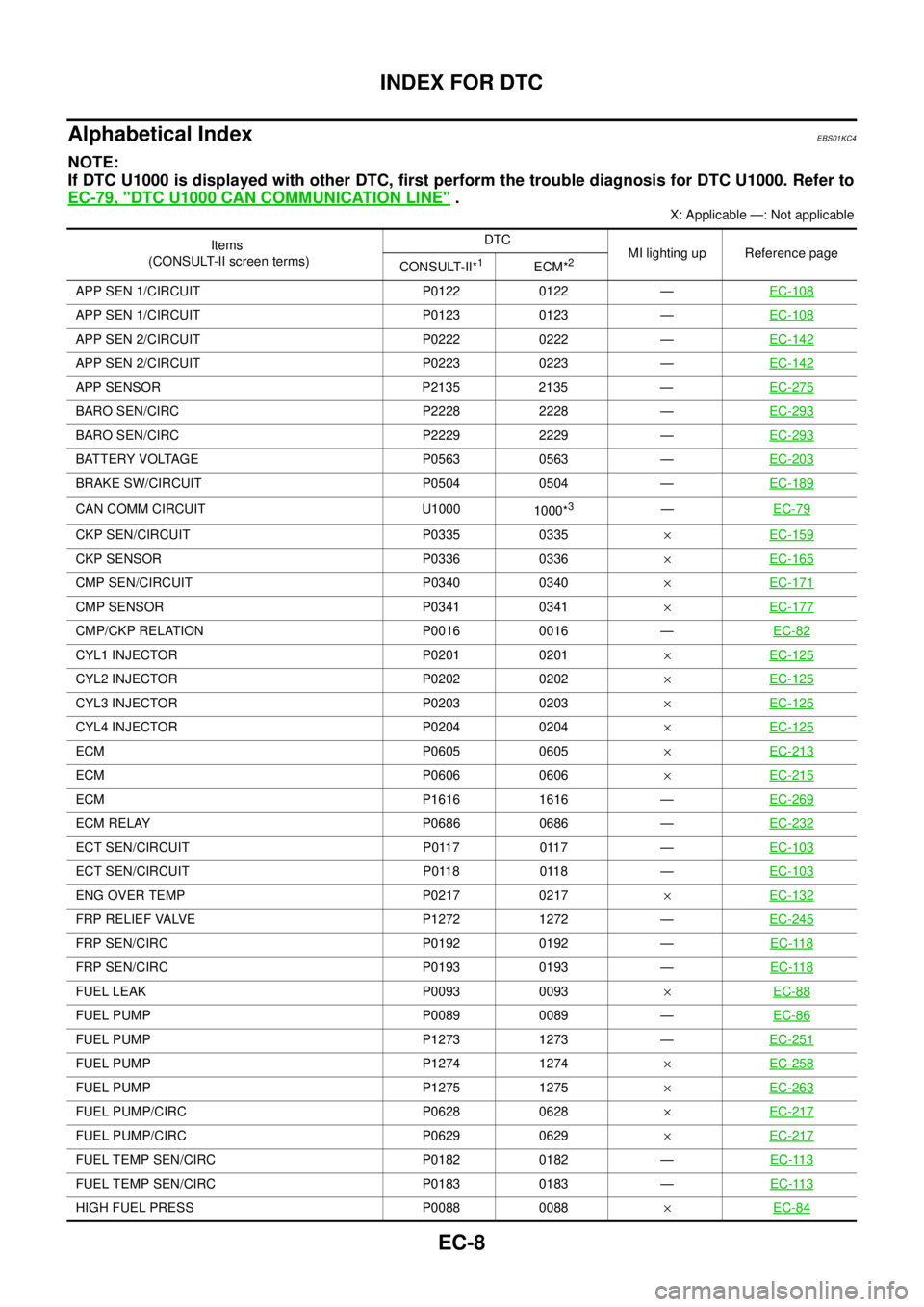
Alphabetical Index
EBS01KC4
NOTE:
If DTC U1000 is displayed with other DTC, first perform the trouble diagnosis for DTC U1000. Refer to
EC-79, "
DTC U1000 CAN COMMUNICATION LINE".
X: Applicable —: Not applicable
Items
(CONSULT-II screen terms)DTC
MI lighting up Reference page
CONSULT-II*
1ECM*2
APP SEN 1/CIRCUIT P0122 0122 —EC-108
APP SEN 1/CIRCUIT P0123 0123 —EC-108
APP SEN 2/CIRCUIT P0222 0222 —EC-142
APP SEN 2/CIRCUIT P0223 0223 —EC-142
APP SENSOR P2135 2135 —EC-275
BARO SEN/CIRC P2228 2228 —EC-293
BARO SEN/CIRC P2229 2229 —EC-293
BATTERY VOLTAGE P0563 0563 —EC-203
BRAKE SW/CIRCUIT P0504 0504 —EC-189
CAN COMM CIRCUIT U1000
1000*3—EC-79
CKP SEN/CIRCUIT P0335 0335´EC-159
CKP SENSOR P0336 0336´EC-165
CMP SEN/CIRCUIT P0340 0340´EC-171
CMP SENSOR P0341 0341´EC-177
CMP/CKP RELATION P0016 0016 —EC-82
CYL1 INJECTOR P0201 0201´EC-125
CYL2 INJECTOR P0202 0202´EC-125
CYL3 INJECTOR P0203 0203´EC-125
CYL4 INJECTOR P0204 0204´EC-125
ECM P0605 0605´EC-213
ECM P0606 0606´EC-215
ECM P1616 1616 —EC-269
ECM RELAY P0686 0686 —EC-232
ECT SEN/CIRCUIT P0117 0117 —EC-103
ECT SEN/CIRCUIT P0118 0118 —EC-103
ENG OVER TEMP P0217 0217´EC-132
FRP RELIEF VALVE P1272 1272 —EC-245
FRP SEN/CIRC P0192 0192 —EC-118
FRP SEN/CIRC P0193 0193 —EC-118
FUEL LEAK P0093 0093´EC-88
FUEL PUMP P0089 0089 —EC-86
FUEL PUMP P1273 1273 —EC-251
FUEL PUMP P1274 1274´EC-258
FUEL PUMP P1275 1275´EC-263
FUEL PUMP/CIRC P0628 0628´EC-217
FUEL PUMP/CIRC P0629 0629´EC-217
FUEL TEMP SEN/CIRC P0182 0182 —EC-113
FUEL TEMP SEN/CIRC P0183 0183 —EC-113
HIGH FUEL PRESS P0088 0088´EC-84
Page 998 of 3171

EC-18
ENGINE CONTROL SYSTEM
System Chart
EBS01KCD
*1: The input signal is sent to the ECM through CAN communication line.
*2: The output signal is sent from the ECM through CAN communication line.
Fuel Injection Control SystemEBS01KCE
SYSTEM DESCRIPTION
Three types of fuel injection control are provided to accommodate engine operating conditions; normal control,
idle control and start control. The ECM determines the appropriate fuel injection control. Under each control,
the amount of fuel injected is adjusted to improve engine performance.
Pulse signals are sent to fuel injectors according to the input signals to adjust the amount of fuel injected to
preset value.
START CONTROL
Input/Output Signal Chart
Input (Sensor) ECM Function Output (Actuator)
lAccelerator pedal position sensor
lFuel rail pressure sensor
lFuel pump temperature sensor
lEngine coolant temperature sensor
lMass air flow sensor
lIntake air temperature sensor
lCrankshaft position sensor
lCamshaft position sensor
lTurbocharger boost sensor
lWheel sensor*1
lIgnition switch
lASCD steering switch
lASCD brake switch
lASCD clutch switch
lSt o p l a m p s w it c h
lAir conditioner switch*1
lFront air control*1
lPark/neutral position switch
lHeat up switch
lRefrigerant pressure sensor
lBattery voltageFuel injection control Fuel injector and Fuel pump
Fuel injection timing control Fuel injector and Fuel pump
Fuel cut control Fuel injector and Fuel pump
Glow control system
Glow relay and glow indicator lamp*
2
ASCD vehicle speed control Fuel injector and Fuel pump
On board diagnostic system
Malfunction indicator (MI)*
2
EGR volume control EGR volume control valve
Cooling fan control
Cooling fan relay*
2
Turbocharger boost controlTurbocharger boost control solenoid
valve
Intake air control valve controlIntake air control valve control solenoid
valve
Air conditioning cut control
Air conditioner relay*
2
Sensor Input Signal to ECM ECM Function Actuator
Engine coolant temperature sensor Engine coolant temperature
Fuel injection
control (start
control)Fuel injector
Fuel pump Crankshaft position sensor Engine speed
Camshaft position sensor Piston position
Ignition switch Start signal
Fuel rail pressure sensor Fuel rail pressure
Page 1017 of 3171

TROUBLE DIAGNOSIS
EC-37
C
D
E
F
G
H
I
J
K
L
MA
EC
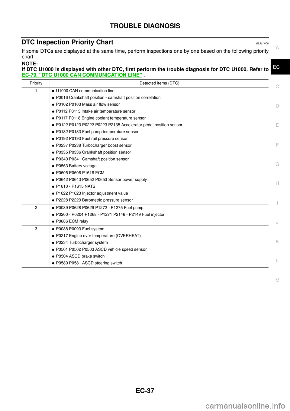
DTC Inspection Priority ChartEBS01KCU
If some DTCs are displayed at the same time, perform inspections one by one based on the following priority
chart.
NOTE:
If DTC U1000 is displayed with other DTC, first perform the trouble diagnosis for DTC U1000. Refer to
EC-79, "
DTC U1000 CAN COMMUNICATION LINE".
Priority Detected items (DTC)
1
lU1000 CAN communication line
lP0016 Crankshaft position - camshaft position correlation
lP0102 P0103 Mass air flow sensor
lP0112 P0113 Intake air temperature sensor
lP0117 P0118 Engine coolant temperature sensor
lP0122 P0123 P0222 P0223 P2135 Accelerator pedal position sensor
lP0182 P0183 Fuel pump temperature sensor
lP0192 P0193 Fuel rail pressure sensor
lP0237 P0238 Turbocharger boost sensor
lP0335 P0336 Crankshaft position sensor
lP0340 P0341 Camshaft position sensor
lP0563 Battery voltage
lP0605 P0606 P1616 ECM
lP0642 P0643 P0652 P0653 Sensor power supply
lP1610 - P1615 NATS
lP1622 P1623 Injector adjustment value
lP2228 P2229 Barometric pressure sensor
2
lP0089 P0628 P0629 P1272 - P1275 Fuel pump
lP0200 - P0204 P1268 - P1271 P2146 - P2149 Fuel injector
lP0686 ECM relay
3
lP0088 P0093 Fuel system
lP0217 Engine over temperature (OVERHEAT)
lP0234 Turbocharger system
lP0501 P0502 P0503 ASCD vehicle speed sensor
lP0504 ASCD brake switch
lP0580 P0581 ASCD steering switch
Page 1028 of 3171

EC-48
TROUBLE DIAGNOSIS
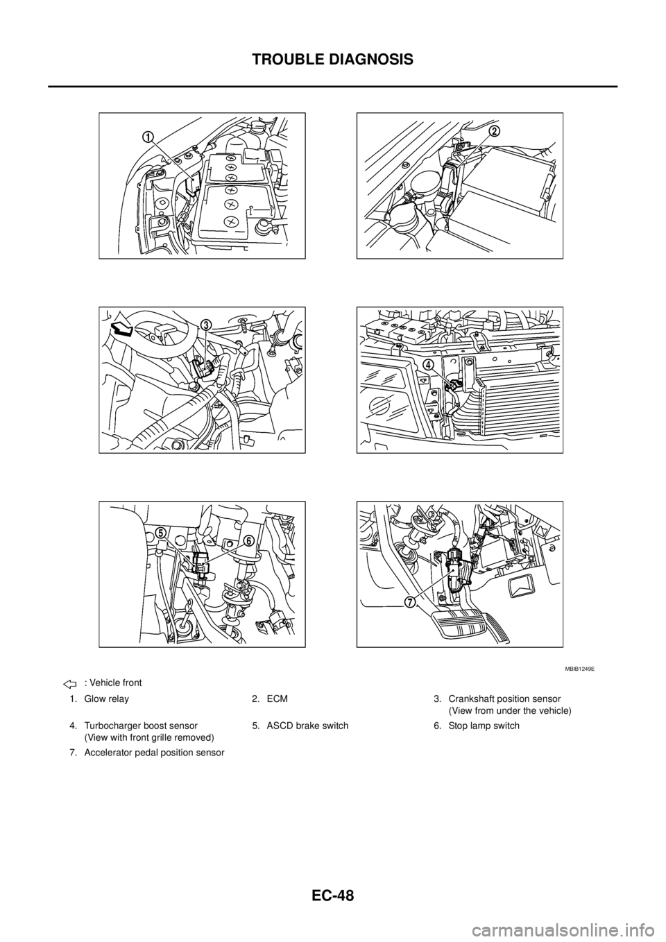
: Vehicle front
1. Glow relay 2. ECM 3. Crankshaft position sensor
(View from under the vehicle)
4. Turbocharger boost sensor
(View with front grille removed)5. ASCD brake switch 6. Stop lamp switch
7. Accelerator pedal position sensor
MBIB1249E