Page 165 of 3171

DTC P1841 ATF PRESSURE SWITCH 1
AT-157
D
E
F
G
H
I
J
K
L
MA
B
AT
Diagnostic ProcedureECS00G1J
1.CHECK INPUT SIGNAL
With CONSULT-II
1. Start engine.
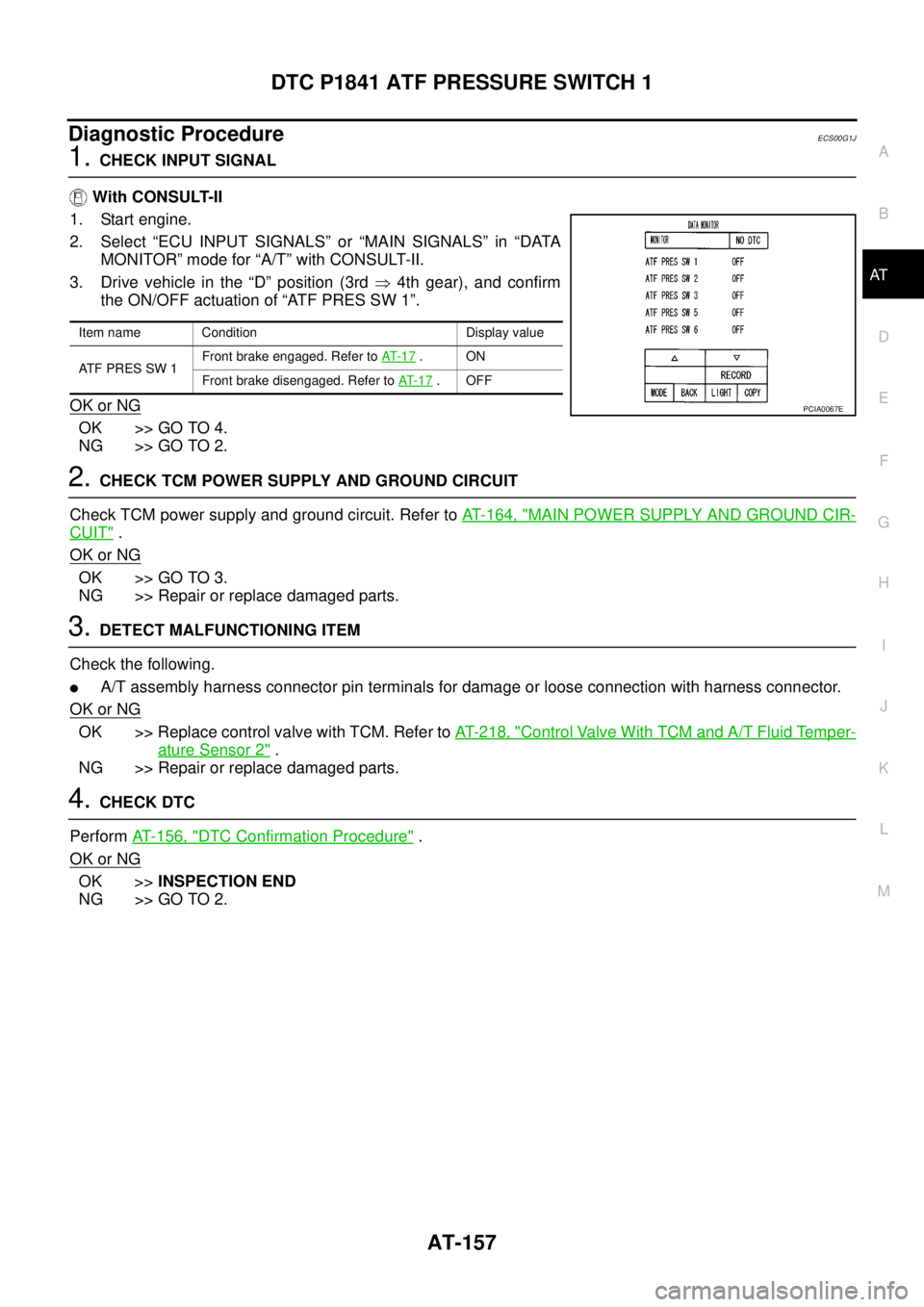
2. Select “ECU INPUT SIGNALS” or “MAIN SIGNALS” in “DATA
MONITOR” mode for “A/T” with CONSULT-II.
3. Drive vehicle in the “D” position (3rd�4th gear), and confirm
the ON/OFF actuation of “ATF PRES SW 1”.
OK or NG
OK >> GO TO 4.
NG >> GO TO 2.
2.CHECK TCM POWER SUPPLY AND GROUND CIRCUIT
Check TCM power supply and ground circuit. Refer toAT- 1 6 4 , "
MAIN POWER SUPPLY AND GROUND CIR-
CUIT".
OK or NG
OK >> GO TO 3.
NG >> Repair or replace damaged parts.
3.DETECT MALFUNCTIONING ITEM
Check the following.
lA/T assembly harness connector pin terminals for damage or loose connection with harness connector.
OK or NG
OK >> Replace control valve with TCM. Refer toAT- 2 1 8 , "Control Valve With TCM and A/T Fluid Temper-
ature Sensor 2".
NG >> Repair or replace damaged parts.
4.CHECK DTC
PerformAT- 1 5 6 , "
DTC Confirmation Procedure".
OK or NG
OK >>INSPECTION END
NG >> GO TO 2.
Item name Condition Display value
AT F P R E S S W 1Front brake engaged. Refer toAT- 1 7
.ON
Front brake disengaged. Refer toAT- 1 7
.OFF
PCIA0067E
Page 214 of 3171

AT-206
TROUBLE DIAGNOSIS FOR SYMPTOMS
Vehicle Does Not Decelerate by Engine Brake
ECS00G82
SYMPTOM:
No engine brake is applied when the gear is shifted from the 22to 11gear.
DIAGNOSTIC PROCEDURE
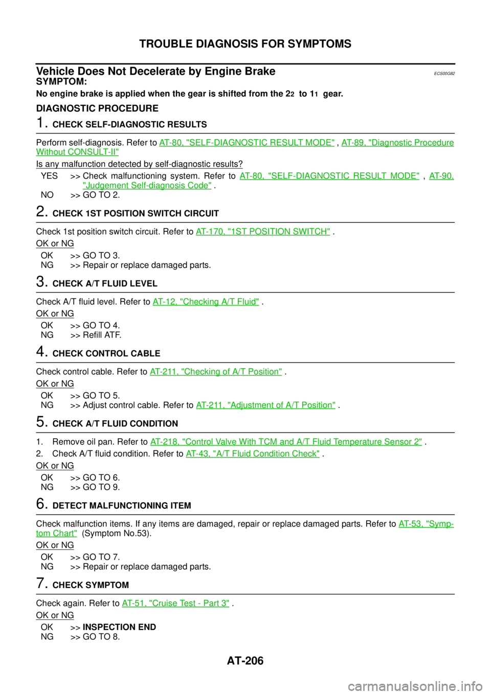
1.CHECK SELF-DIAGNOSTIC RESULTS
Perform self-diagnosis. Refer toAT-80, "
SELF-DIAGNOSTIC RESULT MODE",AT-89, "Diagnostic Procedure
Without CONSULT-II"
Is any malfunction detected by self-diagnostic results?
YES >> Check malfunctioning system. Refer toAT-80, "SELF-DIAGNOSTIC RESULT MODE",AT- 9 0 ,
"Judgement Self-diagnosis Code".
NO >> GO TO 2.
2.CHECK 1ST POSITION SWITCH CIRCUIT
Check 1st position switch circuit. Refer toAT- 1 7 0 , "
1ST POSITION SWITCH".
OK or NG
OK >> GO TO 3.
NG >> Repair or replace damaged parts.
3.CHECK A/T FLUID LEVEL
Check A/T fluid level. Refer toAT-12, "
Checking A/T Fluid".
OK or NG
OK >> GO TO 4.
NG >> Refill ATF.
4.CHECK CONTROL CABLE
Check control cable. Refer toAT- 2 11 , "
Checking of A/T Position".
OK or NG
OK >> GO TO 5.
NG >> Adjust control cable. Refer toAT- 2 11 , "
Adjustment of A/T Position".
5.CHECK A/T FLUID CONDITION
1. Remove oil pan. Refer toAT- 2 1 8 , "
Control Valve With TCM and A/T Fluid Temperature Sensor 2".
2. Check A/T fluid condition. Refer toAT-43, "
A/T Fluid Condition Check".
OK or NG
OK >> GO TO 6.
NG >> GO TO 9.
6.DETECT MALFUNCTIONING ITEM
Check malfunction items. If any items are damaged, repair or replace damaged parts. Refer toAT-53, "
Symp-
tom Chart"(Symptom No.53).
OK or NG
OK >> GO TO 7.
NG >> Repair or replace damaged parts.
7.CHECK SYMPTOM
Check again. Refer toAT-51, "
Cruise Test - Part 3".
OK or NG
OK >>INSPECTION END
NG >> GO TO 8.
Page 283 of 3171
DISASSEMBLY
AT-275
D
E
F
G
H
I
J
K
L
MA
B
AT
49. Remove revolution sensor from transmission case.
CAUTION:
lDo not subject it to impact by dropping or hitting it.
lDo not disassemble.
lDo not allow metal filings, etc. to get on sensor's front
edge magnetic area.
lDo not place in an area affected by magnetism.
50. Remove reverse brake snap ring (fixing plate) using 2 flat-
bladed screwdrivers.
NOTE:
Press out snap ring from transmission case oil pan side
gap using a flat-bladed screwdriver, and remove it using a
another screwdriver.
51. Remove reverse brake retaining plate from transmission case.
lCheck facing for burns, cracks or damage. If necessary,
replace the plate.
52. Remove N-spring from transmission case.
53. Remove reverse brake drive plates, driven plates and dish plate
from transmission case.
lCheck facing for burns, cracks or damage. If necessary,
replace the plate.
SCIA2320E
SCIA5032E
SCIA5214E
SCIA2322E
Page 313 of 3171

ASSEMBLY
AT-305
D
E
F
G
H
I
J
K
L
MA
B
AT
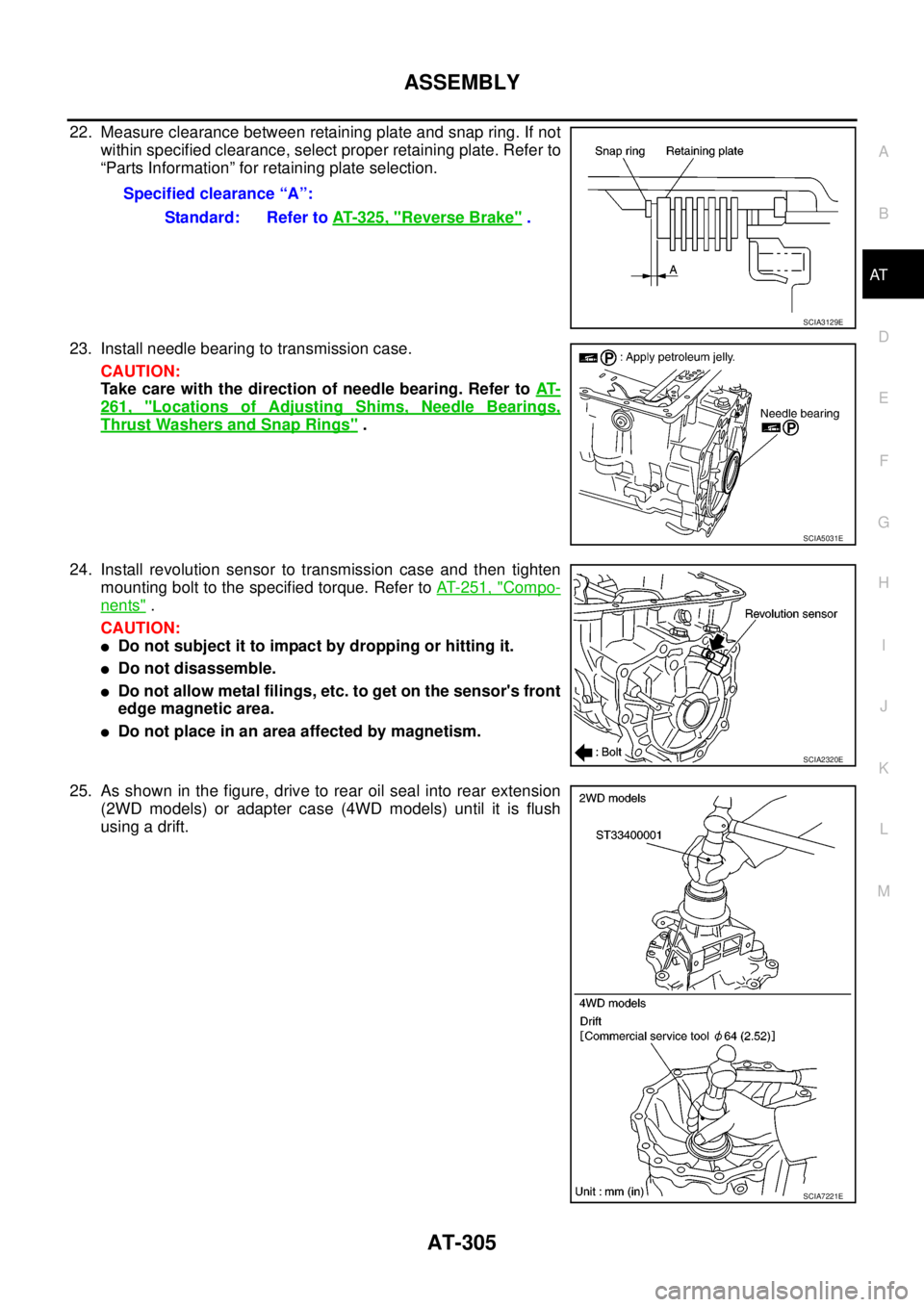
22. Measure clearance between retaining plate and snap ring. If not
within specified clearance, select proper retaining plate. Refer to
“Parts Information” for retaining plate selection.
23. Install needle bearing to transmission case.
CAUTION:
Take care with the direction of needle bearing. Refer toAT-
261, "Locations of Adjusting Shims, Needle Bearings,
Thrust Washers and Snap Rings".
24. Install revolution sensor to transmission case and then tighten
mounting bolt to the specified torque. Refer toAT- 2 5 1 , "
Compo-
nents".
CAUTION:
lDo not subject it to impact by dropping or hitting it.
lDo not disassemble.
lDo not allow metal filings, etc. to get on the sensor's front
edge magnetic area.
lDo not place in an area affected by magnetism.
25. As shown in the figure, drive to rear oil seal into rear extension
(2WD models) or adapter case (4WD models) until it is flush
usingadrift.Specified clearance “A”:
Standard: Refer toAT- 3 2 5 , "
Reverse Brake".
SCIA3129E
SCIA5031E
SCIA2320E
SCIA7221E
Page 325 of 3171
ASSEMBLY
AT-317
D
E
F
G
H
I
J
K
L
MA
B
AT
5. Tighten oil pump mounting bolts to the specified torque. Refer to
AT- 2 5 1 , "
Components".
CAUTION:
Apply ATF to oil pump bushing.
6. Install O-ring to input clutch assembly.
7. Install converter housing to transmission case, and then tighten
mounting bolts to the specified torque. Refer toAT- 2 5 1 , "
Com-
ponents"
8. Make sure that brake band does not close turbine revolution
sensor hole.
9. Install control valve with TCM.
a. Connect TCM connector and park/neutral position switch con-
nector.
SCIA2300E
SCIA5011E
SCIA5171E
SCIA5034E
SCIA5449E
Page 333 of 3171
SERVICE DATA AND SPECIFICATIONS (SDS)
AT-325
D
E
F
G
H
I
J
K
L
MA
B
AT
Vehicle Speed Sensor A/T (Revolution Sensor)ECS00G3V
Turbine Revolution SensorECS00G3U
Reverse BrakeECS00G3W
*: Always check with the Parts Department for the latest parts information.
To ta l E n d P l a yECS00G3X
Name Condition Data (Approx.)
Revolution sensor When moving at 20 km/h (12 MPH). 185 Hz
Name ConditionData
(Approx.)
Turbine revolution
sensor 1When running at 50 km/h (31 MPH) in 4th gear with the closed throttle position signal “OFF”.
1.3 kHz
Turbine revolution
sensor 2When running at 20 km/h (12 MPH) in 1st gear with the closed throttle position signal “OFF”.
Number of drive plates7
Number of driven plates7
Clearance mm (in) Standard 0.7 - 1.1 (0.028 - 0.043)
Total end play [mm (in)] 0.25 - 0.55 (0.0098 - 0.0217)
Page 801 of 3171

LOAD SENSING VALVE
BR-15
C
D
E
G
H
I
J
K
L
MA
B
BR
LOAD SENSING VALVEPFP:46400
Removal and InstallationEFS006A7
CAUTION:
lAlways use a flare nut wrench to remove brake tube. Be careful not to damage flare nut and brake
tube. Also, use flare nut torque wrench for brake tube installation and tightening to the specified
torque. Refer toBR-12, "
Hydraulic Circuit".
lRefill with new brake fluid “DOT 3” or “DOT 4”.
lNever reuse drained brake fluid.
REMOVAL
1. Drain brake fluid.
2. Cover brake line connections/openings to protect them from foreign material such as dust or dirt.
3. Using a flare nut wrench, remove flare nut on brake tube from load sensing valve.
4. Remove mounting bolts to remove load sensing valve.
INSTALLATION
lCarefully performing the following, install in the reverse order of removal.
lAfter installing load sensing valve to vehicle, perform the following: bleed air from brake line. Refer toBR-
11 , "Bleeding Brake System", and check mounting length “L” of sensor spring.
1. Torsion member 2. Load sensing valve bracket 3. Load sensing valve
4. Stopper 5. Sensor spring 6. Rear axle tube
Refer to GI section for symbol marks in the figure.
SFIA3190E
Page 802 of 3171

BR-16
LOAD SENSING VALVE
Inspection
EFS006A8
INSPECTION
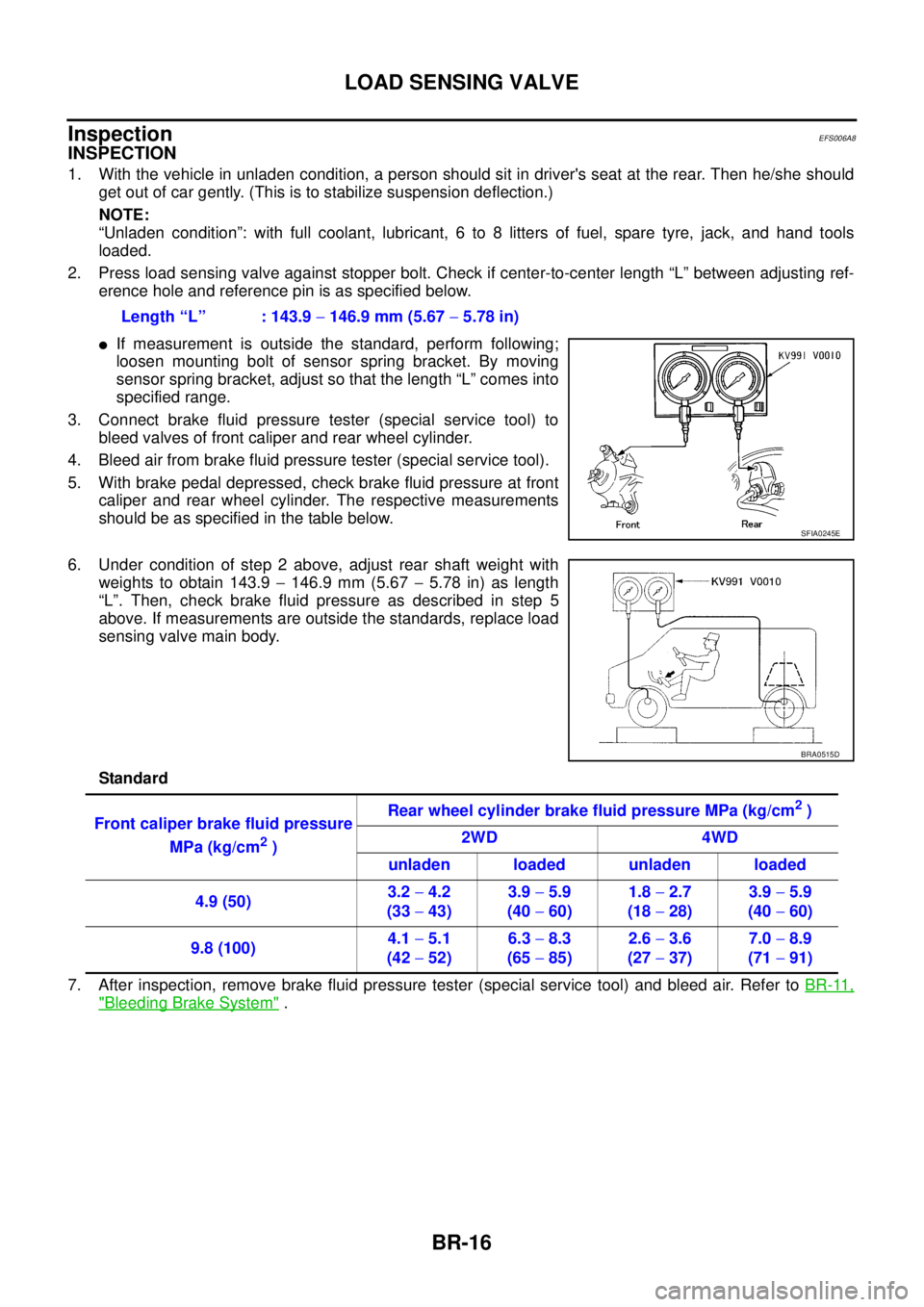
1. With the vehicle in unladen condition, a person should sit in driver's seat at the rear. Then he/she should
get out of car gently. (This is to stabilize suspension deflection.)
NOTE:
“Unladen condition”: with full coolant, lubricant, 6 to 8 litters of fuel, spare tyre, jack, and hand tools
loaded.
2. Press load sensing valve against stopper bolt. Check if center-to-center length “L” between adjusting ref-
erence hole and reference pin is as specified below.
lIf measurement is outside the standard, perform following;
loosen mounting bolt of sensor spring bracket. By moving
sensor spring bracket, adjust so that the length “L” comes into
specified range.
3. Connect brake fluid pressure tester (special service tool) to
bleed valves of front caliper and rear wheel cylinder.
4. Bleed air from brake fluid pressure tester (special service tool).
5. With brake pedal depressed, check brake fluid pressure at front
caliper and rear wheel cylinder. The respective measurements
should be as specified in the table below.
6. Under condition of step 2 above, adjust rear shaft weight with
weights to obtain 143.9-146.9 mm (5.67-5.78 in) as length
“L”. Then, check brake fluid pressure as described in step 5
above. If measurements are outside the standards, replace load
sensing valve main body.
Standard
7. After inspection, remove brake fluid pressure tester (special service tool) and bleed air. Refer toBR-11,
"Bleeding Brake System". Length “L” : 143.9-146.9 mm (5.67-5.78 in)
SFIA0245E
BRA0515D
Front caliper brake fluid pressure
MPa (kg/cm
2)Rear wheel cylinder brake fluid pressure MPa (kg/cm
2)
2WD 4WD
unladen loaded unladen loaded
4.9 (50)3.2-4.2
(33-43)3.9-5.9
(40-60)1.8-2.7
(18-28)3.9-5.9
(40-60)
9.8 (100)4.1-5.1
(42-52)6.3-8.3
(65-85)2.6-3.6
(27-37)7.0-8.9
(71-91)