2005 NISSAN NAVARA brake sensor
[x] Cancel search: brake sensorPage 83 of 3171
TROUBLE DIAGNOSIS
AT-75
D
E
F
G
H
I
J
K
L
MA
B
AT
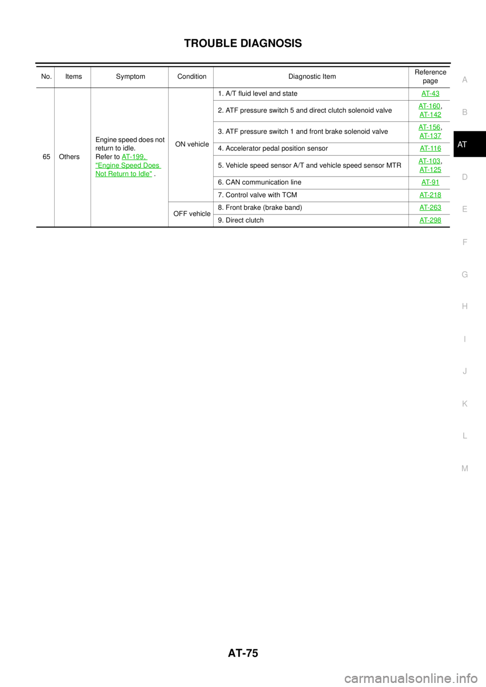
65 OthersEngine speed does not
return to idle.
Refer toAT-199,
"Engine Speed Does
Not Return to Idle".ON vehicle1. A/T fluid level and stateAT- 4 3
2. ATF pressure switch 5 and direct clutch solenoid valveAT-160,
AT-142
3. ATF pressure switch 1 and front brake solenoid valveAT-156,
AT-137
4. Accelerator pedal position sensorAT- 11 6
5. Vehicle speed sensor A/T and vehicle speed sensor MTRAT-103,
AT-125
6. CAN communication lineAT- 9 1
7. Control valve with TCMAT-218
OFF vehicle8. Front brake (brake band)AT-2639. Direct clutchAT-298
No. Items Symptom Condition Diagnostic ItemReference
page
Page 85 of 3171

TROUBLE DIAGNOSIS
AT-77
D
E
F
G
H
I
J
K
L
MA
B
AT
CONSULT-II Function (A/T)ECS00FXA
CONSULT-II can display each diagnostic item using the diagnostic test modes shown following.
FUNCTION
CONSULT-II REFERENCE VALUE
NOTICE:
1. The CONSULT-II electrically displays shift timing and lock-up timing (that is, operation timing of each sole-
noid).
Check for time difference between actual shift timing and the CONSULT-II display. If the difference is
noticeable, mechanical parts (except solenoids, sensors, etc.) may be malfunctioning. Check mechanical
parts using applicable diagnostic procedures.
2. Shift schedule (which implies gear position) displayed on CONSULT-II and that indicated in Service Man-
ual may differ slightly. This occurs because of the following reasons:
–Actual shift schedule has more or less tolerance or allowance,
–Shift schedule indicated in Service Manual refers to the point where shifts start, and
–Gear position displayed on CONSULT-II indicates the point where shifts are completed.
3. Display of solenoid valves on CONSULT-II changes at the start of shifting, while gear position is displayed
upon completion of shifting (which is computed by TCM).
Diagnostic test mode Function Reference page
Self-diagnostic results Self-diagnostic results can be read and erased quickly.AT- 8 0
Data monitor Input/Output data in the ECU can be read.AT- 8 3
CAN diagnostic support
monitorThe results of transmit/receive diagnosis of CAN communication can be read.AT- 8 6
Function testConducted by CONSULT-II instead of a technician to determine whether each system
is “OK” or “NG”.—
DTC work support Select the operating condition to confirm Diagnostic Trouble Codes.AT- 8 6
ECU part number ECU part number can be read. —
Item name Condition Display value (Approx.)
VHCL/S SE-A/T
During drivingApproximately matches the speed-
ometer reading.
VHCL/S SE-MTR
ACCELE POSIReleased accelerator pedal. 0.0/8
Fully depressed accelerator pedal. 8.0/8
CLSD THL POSReleased accelerator pedal. ON
Fully depressed accelerator pedal. OFF
W/O THL POSFully depressed accelerator pedal. ON
Released accelerator pedal. OFF
BRAKE SWDepressed brake pedal. ON
Released brake pedal. OFF
ENGINE SPEED Engine runningClosely matches the tachometer
reading.
TURBINE REV During driving (lock-up ON)Approximately matches the engine
speed.
ATFTEMPSE1
0°C(32°F)-20°C(68°F)-80°C (176°F)3.3 - 2.7 - 0.9 V
ATFTEMPSE23.3 - 2.5 - 0.7 V
TCC SOLENOID When perform lock-up 0.4 - 0.6 A
LINE PRES SOL During driving 0.2 - 0.6 A
FR/B SOLENOIDFront brake engaged. Refer toAT- 1 7
. 0.6 - 0.8 A
Front brake disengaged. Refer toAT- 1 7
.0-0.05A
Page 91 of 3171
TROUBLE DIAGNOSIS
AT-83
D
E
F
G
H
I
J
K
L
MA
B
AT
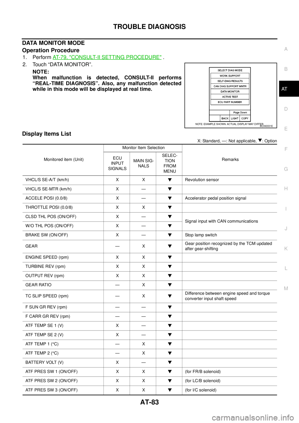
DATA MONITOR MODE
Operation Procedure
1. PerformAT-79, "CONSULT-II SETTING PROCEDURE".
2. Touch “DATA MONITOR”.
NOTE:
When malfunction is detected, CONSULT-II performs
“REAL-TIME DIAGNOSIS”. Also, any malfunction detected
while in this mode will be displayed at real time.
Display Items List
X: Standard, —: Not applicable, : Option
BCIA0031E
Monitored item (Unit)Monitor Item Selection
Remarks ECU
INPUT
SIGNALSMAIN SIG-
NALSSELEC-
TION
FROM
MENU
VHCL/S SE-A/T (km/h) X X Revolution sensor
VHCL/S SE-MTR (km/h) X —
ACCELE POSI (0.0/8) X — Accelerator pedal position signal
THROTTLE POSI (0.0/8) X X
CLSD THL POS (ON/OFF) X —
Signal input with CAN communications
W/O THL POS (ON/OFF) X —
BRAKE SW (ON/OFF) X — Stop lamp switch
GEAR — XGear position recognized by the TCM updated
after gear-shifting
ENGINE SPEED (rpm) X X
TURBINE REV (rpm) X X
OUTPUT REV (rpm) X X
GEAR RATIO — X
TC SLIP SPEED (rpm) — XDifference between engine speed and torque
converter input shaft speed
F SUN GR REV (rpm) — —
F CARR GR REV (rpm) — —
ATFTEMPSE1(V) X —
ATFTEMPSE2(V) X —
AT F T E M P 1 (°C) — X
AT F T E M P 2 (°C) — X
BATTERY VOLT (V) X —
ATF PRES SW 1 (ON/OFF) X X (for FR/B solenoid)
ATF PRES SW 2 (ON/OFF) X X (for LC/B solenoid)
ATF PRES SW 3 (ON/OFF) X X (for I/C solenoid)
Page 98 of 3171
AT-90
TROUBLE DIAGNOSIS
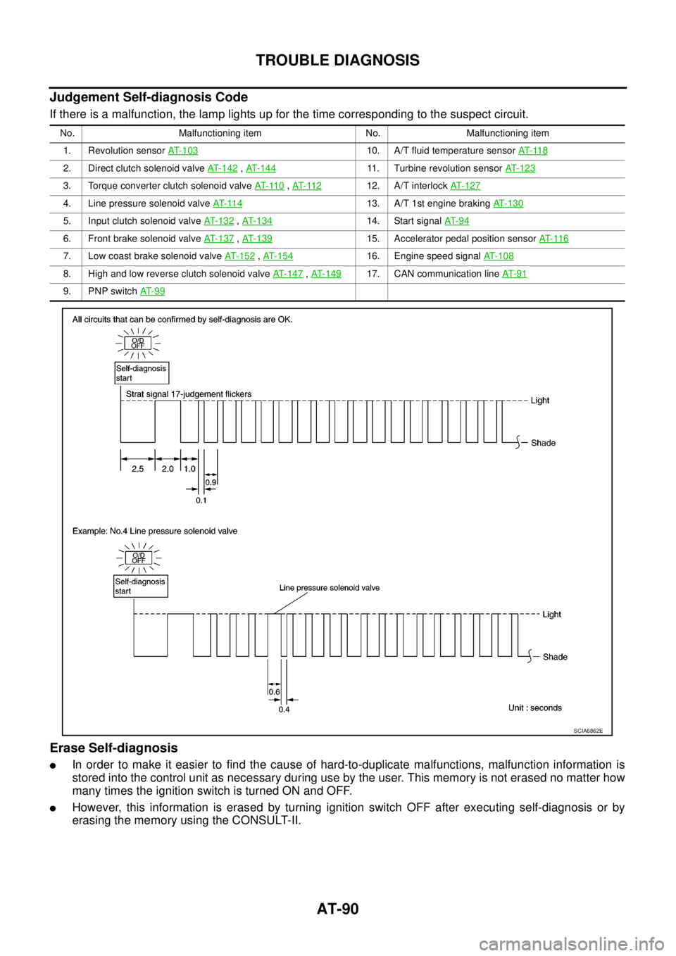
Judgement Self-diagnosis Code
If there is a malfunction, the lamp lights up for the time corresponding to the suspect circuit.
Erase Self-diagnosis
lIn order to make it easier to find the cause of hard-to-duplicate malfunctions, malfunction information is
stored into the control unit as necessary during use by the user. This memory is not erased no matter how
many times the ignition switch is turned ON and OFF.
lHowever, this information is erased by turning ignition switch OFF after executing self-diagnosis or by
erasing the memory using the CONSULT-II.
No. Malfunctioning item No. Malfunctioning item
1. Revolution sensorAT- 1 0 3
10. A/T fluid temperature sensorAT- 11 8
2. Direct clutch solenoid valveAT- 1 4 2,AT-14411. Turbine revolution sensorAT- 1 2 3
3. Torque converter clutch solenoid valveAT- 11 0,AT- 11 212. A/T interlockAT-127
4. Line pressure solenoid valveAT- 11 413. A/T 1st engine brakingAT-130
5. Input clutch solenoid valveAT- 1 3 2,AT- 1 3 414. Start signalAT- 9 4
6. Front brake solenoid valveAT-137,AT- 1 3 915. Accelerator pedal position sensorAT- 11 6
7. Low coast brake solenoid valveAT- 1 5 2,AT- 1 5 416. Engine speed signalAT-108
8. High and low reverse clutch solenoid valveAT-147,AT- 1 4 917. CAN communication lineAT- 9 1
9. PNP switchAT- 9 9
SCIA6862E
Page 135 of 3171
DTC P1730 A/T INTERLOCK
AT-127
D
E
F
G
H
I
J
K
L
MA
B
AT
DTC P1730 A/T INTERLOCKPFP:00000
DescriptionECS00FZE
Fail-safe function to detect interlock conditions.
On Board Diagnosis LogicECS00FZF
lDiagnostic trouble code “P1730 A/T INTERLOCK” with CONSULT-II or 12th judgement flicker without
CONSULT-II is detected when TCM does not receive the proper voltage signal from the sensor and
switch.
lTCM monitors and compares gear position and conditions of each ATF pressure switch when gear is
steady.
Possible CauseECS00FZG
lHarness or connectors
(The solenoid and switch circuit is open or shorted.)
lLow coast brake solenoid valve
lATFpressureswitch2
DTC Confirmation ProcedureECS00FZH
CAUTION:
Always drive vehicle at a safe speed.
NOTE:
If “DTC Confirmation Procedure” has been previously performed, always turn ignition switch OFF and
wait at least 10 seconds before performing the next test.
After the repair, perform the following procedure to confirm the malfunction is eliminated.
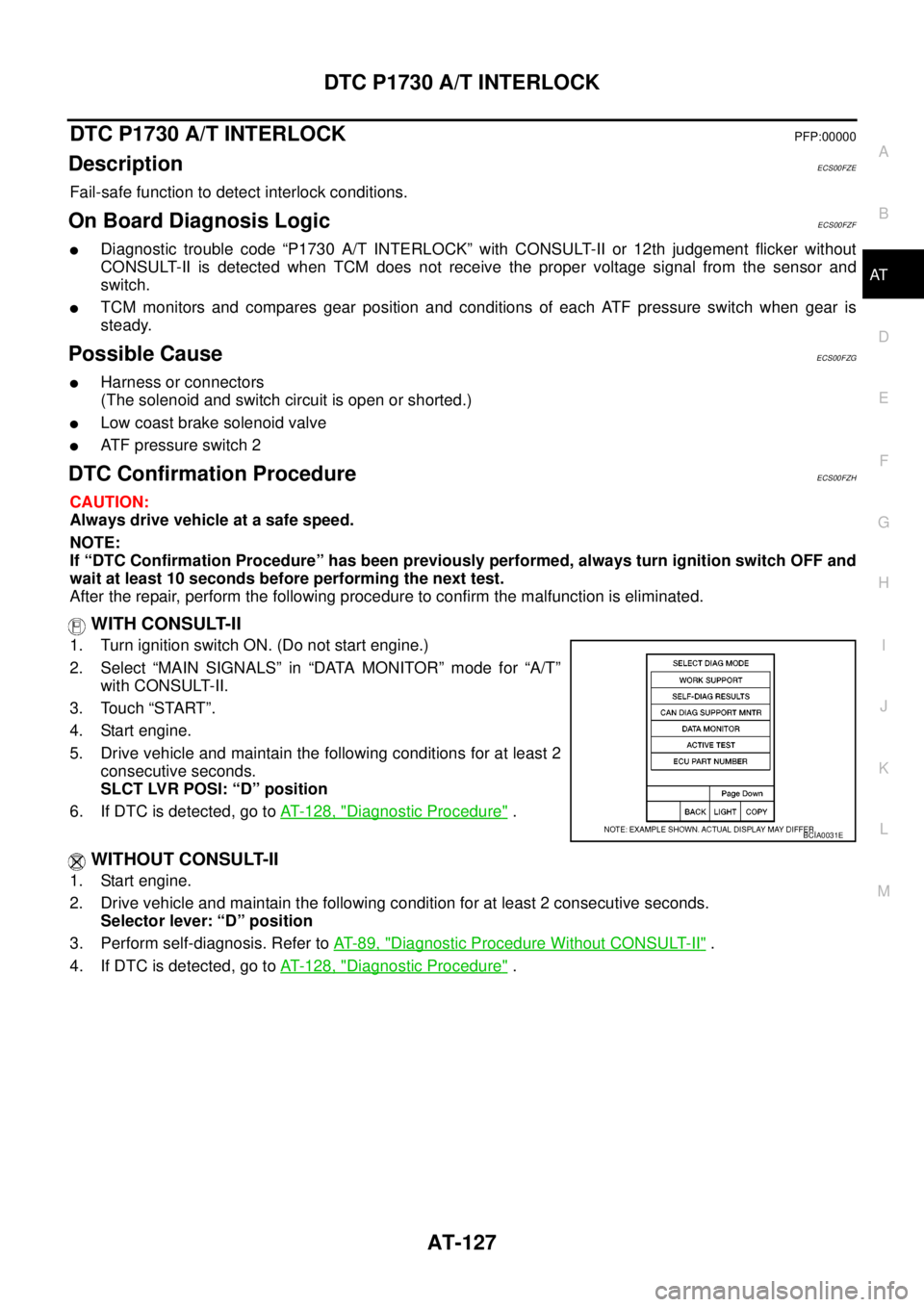
WITH CONSULT-II
1. Turn ignition switch ON. (Do not start engine.)
2. Select “MAIN SIGNALS” in “DATA MONITOR” mode for “A/T”
with CONSULT-II.
3. Touch “START”.
4. Start engine.
5. Drive vehicle and maintain the following conditions for at least 2
consecutive seconds.
SLCT LVR POSI: “D” position
6. If DTC is detected, go toAT- 1 2 8 , "
Diagnostic Procedure".
WITHOUT CONSULT-II
1. Start engine.
2. Drive vehicle and maintain the following condition for at least 2 consecutive seconds.
Selector lever: “D” position
3. Perform self-diagnosis. Refer toAT-89, "
Diagnostic Procedure Without CONSULT-II".
4. If DTC is detected, go toAT- 1 2 8 , "
Diagnostic Procedure".
BCIA0031E
Page 136 of 3171
AT-128
DTC P1730 A/T INTERLOCK
Judgement of A/T Interlock
ECS00FZI
When A/T Interlock is judged to be malfunctioning, the vehicle should be fixed in 2nd gear, and should be set
in a condition in which it can travel.
When one of the following fastening patterns is detected, the fail-safe function in correspondence with the indi-
vidual pattern should be performed.
NOTE:
When the vehicle is driven fixed in 2nd gear, a turbine revolution sensor malfunction is displayed, but
this is not a turbine revolution sensor malfunction.
A/T INTERLOCK COUPLING PATTERN TABLE
l:NG,X:OK
Diagnostic ProcedureECS00FZJ
1.CHECK SELF-DIAGNOSTIC RESULTS
With CONSULT-II
1. Drive vehicle.
2. Stop vehicle and turn ignition switch OFF.
3. Turn ignition switch ON. (Do not start engine.)
4. Select “SELF-DIAG RESULTS” mode for “A/T” with CONSULT-
II.
Without CONSULT-II
1. Drive vehicle.
2. Stop vehicle and turn ignition switch OFF.
3. Turn ignition switch ON. (Do not start engine.)
4. Perform self-diagnosis. Refer toAT-89, "
TCM SELF-DIAGNOSTIC PROCEDURE (WITHOUT CONSULT-
II)".
OK or NG
OK >> GO TO 2.
NG >> Check low coast brake solenoid valve circuit and function. Refer toAT- 1 5 2 , "
DTC P1772 LOW
COAST BRAKE SOLENOID VALVE",AT- 1 5 4 , "DTC P1774 LOW COAST BRAKE SOLENOID
VALVE FUNCTION".
2.CHECK DTC
PerformAT- 1 2 7 , "
DTC Confirmation Procedure".
OK or NG
OK >>INSPECTION END
NG >> GO TO 3.
Gear positionATF pressure switch output
Fail-safe
functionClutch pressure output pattern after fail-safe
function
SW3
(I/C)SW6
(HLR/C)SW5
(D/C)SW1
(FR/B)SW2
(LC/B)I/C HLR/C D/C FR/B LC/B L/U
A/T interlock
coupling pattern3rd – X X –lHeld in
2nd gearOFF OFF ON OFF OFF OFF
4th – X X –lHeld in
2nd gearOFF OFF ON OFF OFF OFF
5th X X – XlHeld in
2nd gearOFF OFF ON OFF OFF OFF
BCIA0031E
Page 138 of 3171
AT-130
DTC P1731 A/T 1ST ENGINE BRAKING
DTC P1731 A/T 1ST ENGINE BRAKING
PFP:00000
DescriptionECS00FZK
Fail-safe function to prevent sudden decrease in speed by engine brake other than at “1” position.
CONSULT-II Reference ValueECS00FZL
On Board Diagnosis LogicECS00FZM
Diagnostic trouble code “P1731 A/T 1ST E/BRAKING” with CONSULT-II or 13th judgement flicker without
CONSULT-II is detected under the following conditions.
lWhen TCM does not receive the proper voltage signal from the sensor.
lWhen TCM monitors each ATF pressure switch and solenoid monitor value, and detects as irregular when
engine brake of 1st gear acts other than at “1” position.
Possible CauseECS00FZN
lHarness or connectors
(The sensor circuit is open or shorted.)
lLow coast brake solenoid valve
lATF pressure switch 2
DTC Confirmation ProcedureECS00FZO
CAUTION:
lAlways drive vehicle at a safe speed.
lBe careful not to rev engine into the red zone on the tachometer.
NOTE:
If “DTC Confirmation Procedure” has been previously preformed, always turn ignition switch OFF and
wait at least 10 seconds before performing the next test.
After the repair, perform the following procedure to confirm the malfunction is eliminated.
WITH CONSULT-II
1. Turn ignition switch ON. (Do not start engine.)
2. Select “MAIN SIGNALS” in “DATA MONITOR” mode for “A/T”
with CONSULT-II.
3. Touch “START”.
4. Start engine.
5. Drive vehicle and maintain the following conditions for at least 2
consecutive seconds.
ENGINE SPEED: 1,200 rpm or more
SLCT LVR POSI: “1” position
GEAR: “1” position
6. If DTC is detected, go toAT- 1 3 1 , "
Diagnostic Procedure".
WITHOUT CONSULT-II
1. Start engine.
2. Drive vehicle and maintain the following conditions for at least 2 consecutive seconds.
Engine speed: 1,200 rpm or more
Selector lever position: “1” position
Gear position: “1” position
3. Perform self-diagnosis. Refer toAT-89, "
Diagnostic Procedure Without CONSULT-II".
4. If DTC is detected, go toAT- 1 3 1 , "
Diagnostic Procedure".
Item name Condition Display value
ON OFF SOLLow coast brake engaged. Refer toAT- 1 7
.ON
Low coast brake disengaged. Refer toAT- 1 7
.OFF
AT F P R E S S W 2Low coast brake engaged. Refer toAT- 1 7
.ON
Low coast brake disengaged. Refer toAT- 1 7
.OFF
BCIA0031E
Page 139 of 3171

DTC P1731 A/T 1ST ENGINE BRAKING
AT-131
D
E
F
G
H
I
J
K
L
MA
B
AT
Diagnostic ProcedureECS00FZP
1.CHECK INPUT SIGNALS
With CONSULT-II
1. Start the engine.
2. Select “SELECTION FROM MENU” in “DATA MONITOR” mode
for “A/T” with CONSULT-II.
3. Drive vehicle in the “1 ” position (1st gear), and confirm the ON/
OFF actuation of “ATF PRES SW 2” and “ON OFF SOL”.
OK or NG
OK >> GO TO 4.
NG >> GO TO 2.
2.CHECK TCM POWER SUPPLY AND GROUND CIRCUIT
Check TCM power supply and ground circuit. Refer toAT- 1 6 4 , "
MAIN POWER SUPPLY AND GROUND CIR-
CUIT".
OK or NG
OK >> GO TO 3.
NG >> Repair or replace damaged parts.
3.DETECT MALFUNCTIONING ITEM
Check the following.
lA/T assembly harness connector pin terminals for damage or loose connection with harness connector.
OK or NG
OK >> Replace control valve with TCM. Refer toAT- 2 1 8 , "Control Valve With TCM and A/T Fluid Temper-
ature Sensor 2".
NG >> Repair or replace damaged parts.
4.CHECK DTC
PerformAT- 1 3 0 , "
DTC Confirmation Procedure".
OK or NG
OK >>INSPECTION END
NG >> GO TO 2.
Item name Condition Display value
ON OFF SOLLow coast brake engaged. Refer toAT- 1 7
.ON
Low coast brake disengaged. Refer toAT- 1 7
.OFF
AT F P R E S S W 2Low coast brake engaged. Refer toAT- 1 7
.ON
Low coast brake disengaged. Refer toAT- 1 7
.OFF
SCIA4670E