2005 NISSAN NAVARA brake fluid
[x] Cancel search: brake fluidPage 853 of 3171
![NISSAN NAVARA 2005 Repair Workshop Manual TROUBLE DIAGNOSIS
BRC-31
[ABS]
C
D
E
G
H
I
J
K
L
MA
B
BRC
2.CHECK HARNESS
1. Turn ignition switch OFF and disconnect combination meter con-
nector M23.
2. Check continuity between brake fluid level sw NISSAN NAVARA 2005 Repair Workshop Manual TROUBLE DIAGNOSIS
BRC-31
[ABS]
C
D
E
G
H
I
J
K
L
MA
B
BRC
2.CHECK HARNESS
1. Turn ignition switch OFF and disconnect combination meter con-
nector M23.
2. Check continuity between brake fluid level sw](/manual-img/5/57362/w960_57362-852.png)
TROUBLE DIAGNOSIS
BRC-31
[ABS]
C
D
E
G
H
I
J
K
L
MA
B
BRC
2.CHECK HARNESS
1. Turn ignition switch OFF and disconnect combination meter con-
nector M23.
2. Check continuity between brake fluid level switch connector
E65, combination meter connector M23 and ground.
OK or NG
OK >> INSPECTION END
NG >> If the open or short in harness, repair or replace harness.
SFIA3053E
Brake fluid level switch
(harness connector E65)Combination meter
(harness connector M23)Continuity
132Yes
Ground 32 No
2 Ground Yes
Page 854 of 3171
![NISSAN NAVARA 2005 Repair Workshop Manual BRC-32
[ABS]
TROUBLE DIAGNOSIS
Inspection 7 Parking Brake Switch Circuit
EFS005U6
INSPECTION PROCEDURE
1.CHECK PARKING BRAKE SWITCH
1. Turn ignition switch OFF and disconnect parking brake switch
conn NISSAN NAVARA 2005 Repair Workshop Manual BRC-32
[ABS]
TROUBLE DIAGNOSIS
Inspection 7 Parking Brake Switch Circuit
EFS005U6
INSPECTION PROCEDURE
1.CHECK PARKING BRAKE SWITCH
1. Turn ignition switch OFF and disconnect parking brake switch
conn](/manual-img/5/57362/w960_57362-853.png)
BRC-32
[ABS]
TROUBLE DIAGNOSIS
Inspection 7 Parking Brake Switch Circuit
EFS005U6
INSPECTION PROCEDURE
1.CHECK PARKING BRAKE SWITCH
1. Turn ignition switch OFF and disconnect parking brake switch
connector (LHD model: B12, RHD model: B109). For brake fluid
level switch, refer toDI-10, "
Wiring Diagram—METER—".
2. Check continuity between parking brake switch connector and
ground.
OK or NG
OK >> GO TO 2.
NG >> Replace parking brake switch.
2.CHECK HARNESS
1. Disconnect combination meter connector M23.
2. Check continuity between parking brake switch connector (LHD
model: B12, RHD model: B109), combination meter connector
M23 and ground.
OK or NG
OK >> INSPECTION END
NG >> If the open or short in harness, repair or replace harness.
SFIA2935E
Measurement condition Continuity
When the parking brake pedal is operated. Yes
When the parking brake pedal is not operated. No
SFIA3055E
Parking brake switch
(harness connector B12, B109)Combination meter
(harness connector M23)Continuity
131Yes
1 Ground No
Page 856 of 3171
![NISSAN NAVARA 2005 Repair Workshop Manual BRC-34
[ABS]
TROUBLE DIAGNOSIS
4.CHECK ABS WARNING LAMP DISPLAY
Make sure that the ABS warning lamp is turned off after the ignition switch is turned ON or when driving.
OK or NG
OK >> Normal
NG >> Pe NISSAN NAVARA 2005 Repair Workshop Manual BRC-34
[ABS]
TROUBLE DIAGNOSIS
4.CHECK ABS WARNING LAMP DISPLAY
Make sure that the ABS warning lamp is turned off after the ignition switch is turned ON or when driving.
OK or NG
OK >> Normal
NG >> Pe](/manual-img/5/57362/w960_57362-855.png)
BRC-34
[ABS]
TROUBLE DIAGNOSIS
4.CHECK ABS WARNING LAMP DISPLAY
Make sure that the ABS warning lamp is turned off after the ignition switch is turned ON or when driving.
OK or NG
OK >> Normal
NG >> Perform self-diagnosis. Refer toBRC-18, "
Self-Diagnosis".
Symptom 2: Unexpected Pedal ReactionEFS005U9
1.CHECK BRAKE PEDAL STROKE
Check brake pedal stroke. Refer toBR-6, "
Inspection and Adjustment".
Is the stroke too big?
YES >>lBleed air from brake piping. Refer toBR-11, "Bleeding Brake System".
lCheck brake pedal, brake booster, and master cylinder for mount play, looseness, brake sys-
tem fluid leakage, etc. Repair if necessary. Refer to Brake pedal:BR-8, "
COMPONENTS",
brake booster and master cylinder:BR-20, "
COMPONENTS".
NO >> GO TO 2.
2.CHECK FUNCTION
Disconnect ABS actuator and electric unit (control unit) connector to deactivate ABS. Check if braking force is
normal in this condition. Connect connector after inspection.
OK or NG
OK >> GO TO procedure 3 “CHECK WHEEL SENSOR AND SENSOR ROTOR” of symptom 1. Refer to
BRC-33, "
Symptom 1: Excessive ABS Function Operation Frequency".
NG >> Check the following system. If any malfunction is found, repair or replace malfunctioning parts.
lBrake booster. Refer toBR-19, "BRAKE BOOSTER".
lHydraulic line. Refer toBR-12, "BRAKE TUBE AND HOSE".
lFront brake caliper. Refer toBR-24, "FRONT DISC BRAKE".
lRear wheel cylinder. Refer toBR-30, "REAR DRUM BRAKE".
Symptom 3: The Stopping Distance Is LongEFS005UA
CAUTION:
The stopping distance on slippery road surfaces might be longer with the ABS operating than when
the ABS is not operating.
1.CHECK FUNCTION
Turn ignition switch OFF. Disconnect ABS actuator and electric unit (control unit) connector to deactivate ABS.
In this condition, check stopping distance. After inspection, connect connector.
OK or NG
OK >> GO TO procedure 3 “CHECK WHEEL SENSOR AND SENSOR ROTOR” of symptom 1. Refer to
BRC-33, "
Symptom 1: Excessive ABS Function Operation Frequency".
NG >>
lBleed air from the brake piping. Refer toBR-11, "Bleeding Brake System".
lCheck the following system. If any malfunction is found, repair or replace malfunctioning parts.
–Brake booster. Refer toBR-19, "BRAKE BOOSTER".
–Hydraulic line. Refer toBR-12, "BRAKE TUBE AND HOSE".
–Front brake caliper. Refer toBR-24, "FRONT DISC BRAKE".
–Rear wheel cylinder. Refer toBR-30, "REAR DRUM BRAKE".
Page 866 of 3171

CL-2
PRECAUTIONS
PRECAUTIONS
PFP:00001
ServiceNoticeorPrecautionsECS00ICC
lRecommended clutch fluid is brake fluid “DOT 3” or “DOT 4”. Refer toMA-14, "RECOMMENDED FLUIDS
AND LUBRICANTS".
lDo not reuse drained clutch fluid.
lBe careful not to splash clutch fluid on painted areas.
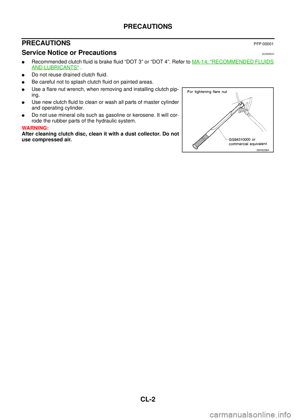
lUse a flare nut wrench, when removing and installing clutch pip-
ing.
lUse new clutch fluid to clean or wash all parts of master cylinder
and operating cylinder.
lDo not use mineral oils such as gasoline or kerosene. It will cor-
rode the rubber parts of the hydraulic system.
WARNING:
After cleaning clutch disc, clean it with a dust collector. Do not
use compressed air.
SBR820BA
Page 928 of 3171

DI-18
COMBINATION METERS
NOTE:
Some items are not available according to vehicle specification.
*: Monitor indicating “OFF” when brake warning lamp is on because of parking brake operation or low brake
fluid level continues.
Trouble DiagnosisEKS00L8M
HOW TO PERFORM TROUBLE DIAGNOSIS
1. Confirm the symptom or customer complaint.
2. Perform preliminary check. Refer toDI-19, "
PRELIMINARY CHECK".
3. According to the symptom chart, make sure of the symptom cause and repair or replace applicable parts.
Refer toDI-19, "
Symptom Chart".
4. Does the meter operate normally? If so, GO TO 5. If not, GO TO 2.
5. INSPECTION END
KEY G W/L [ON/OFF] X Indicates [ON/OFF] condition of KEY warning lamp (green).
KEY R W/L [ON/OFF] X Indicates [ON/OFF] condition of KEY warning lamp (red).
KEY KNOB W/L [ON/OFF] X Indicates [ON/OFF] condition of LOCK warning lamp.
M RANGE SW [ON/OFF] X X Indicates [ON/OFF] condition of manual mode range switch.
NM RANGE SW [ON/OFF] X XIndicates [ON/OFF] condition of except for manual mode range
switch.
AT SFT UP SW [ON/OFF] X X Indicates [ON/OFF] condition of A/T shift-up switch.
AT SFT DWN SW [ON/OFF] X X Indicates [ON/OFF] condition of A/T shift-down switch.
O/D OFF SW [ON/OFF] X Indicates [ON/OFF] condition of OD OFF switch.
BRAKE SW [ON/OFF] X Indicates [ON/OFF] condition of parking brake switch.
AT-M IND [ON/OFF] X X Indicates [ON/OFF] condition of A/T manual mode indicator.
AT-MGEAR[1,2,3,4,5] X XIndicates [1, 2, 3, 4, 5] condition of A/T manual mode gear
position.
P RANGE IND [ON/OFF] X X Indicates [ON/OFF] condition of A/T shift P range indicator.
R RANGE IND [ON/OFF] X X Indicates [ON/OFF] condition of A/T shift R range indicator.
N RANGE IND [ON/OFF] X X Indicates [ON/OFF] condition of A/T shift N range indicator.
D RANGE IND [ON/OFF] X X Indicates [ON/OFF] condition of A/T shift D range indicator.
4 RANGE IND [ON/OFF] X X Indicates [ON/OFF] condition of A/T shift 4 range indicator.
3 RANGE IND [ON/OFF] X X Indicates [ON/OFF] condition of A/T shift 3 range indicator.
2 RANGE IND [ON/OFF] X X Indicates [ON/OFF] condition of A/T shift 2 range indicator.
1 RANGE IND [ON/OFF] X X Indicates [ON/OFF] condition of A/T shift 1range indicator.
O/D OFF W/L [ON/OFF] X Indicates [ON/OFF] condition of OD OFF indicator lamp.
CRUISE IND [ON/OFF] X Indicates [ON/OFF] condition of CRUISE indicator lamp.
SET IND [ON/OFF] X Indicates [ON/OFF] condition of SET indicator lamp.
4WD LOCK SW [ON/OFF] X Indicates [ON/OFF] condition of 4WD LOCK switch.
4WD LOCK IND [ON/OFF] X Indicates [ON/OFF] condition of 4WD LOCK indicator lamp.
4WD W/L [ON/OFF] X Indicates [ON/OFF] condition of 4WD warning lamp.Display item [Unit]MAIN
SIGNALSSELECTION
FROM MENUContents
Page 1447 of 3171

CAMSHAFT
EM-65
C
D
E
F
G
H
I
J
K
L
MA
EM
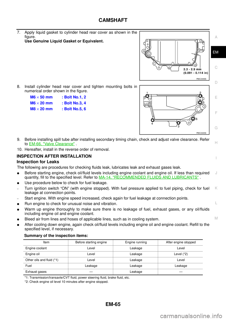
7. Apply liquid gasket to cylinder head rear cover as shown in the
figure.
Use Genuine Liquid Gasket or Equivalent.
8. Install cylinder head rear cover and tighten mounting bolts in
numerical order shown in the figure.
9. Before installing spill tube after installing secondary timing chain, check and adjust valve clearance. Refer
toEM-66, "
Valve Clearance".
10. Hereafter, install in the reverse order of removal.
INSPECTION AFTER INSTALLATION
Inspection for Leaks
The following are procedures for checking fluids leak, lubricates leak and exhaust gases leak.
lBefore starting engine, check oil/fluid levels including engine coolant and engine oil. If less than required
quantity, fill to the specified level. Refer toMA-14, "
RECOMMENDED FLUIDS AND LUBRICANTS".
lUse procedure below to check for fuel leakage.
–Turn ignition switch “ON” (with engine stopped). With fuel pressure applied to fuel piping, check for fuel
leakage at connection points.
–Start engine. With engine speed increased, check again for fuel leakage at connection points.
lRun engine to check for unusual noise and vibration.
lWarm up engine thoroughly to make sure there is no leakage of fuel, exhaust gases, or any oil/fluids
including engine oil and engine coolant.
lBleed air from lines and hoses of applicable lines, such as in cooling system.
lAfter cooling down engine, again check oil/fluid levels including engine oil and engine coolant. Refill to the
specified level, if necessary.
Summary of the inspection items:
*1: Transmission/transaxle/CVT fluid, power steering fluid, brake fluid, etc.
*2: Check engine oil level 10 minutes after engine stopped.
PBIC3446E
M6´50 mm : Bolt No.1, 2
M6´20 mm : Bolt No.3, 4
M8´20 mm : Bolt No.5, 6
PBIC3445E
Item Before starting engine Engine running After engine stopped
Engine coolant Level Leakage Level
Engine oil Level Leakage Level (*2)
Other oils and fluid (*1) Level Leakage Level
Fuel Leakage Leakage Leakage
Exhaust gases — Leakage —
Page 1460 of 3171

EM-78
SECONDARY TIMING CHAIN
Summary of the inspection items:
*1: Transmission/transaxle/CVT fluid, power steering fluid, brake fluid, etc.
*2: Check engine oil level 10 minutes after engine stopped.Item Before starting engine Engine running After engine stopped
Engine coolant Level Leakage Level
Engine oil Level Leakage Level (*2)
Other oils and fluid (*1) Level Leakage Level
Fuel Leakage Leakage Leakage
Exhaust gases — Leakage —
Page 1473 of 3171

PRIMARY TIMING CHAIN
EM-91
C
D
E
F
G
H
I
J
K
L
MA
EM
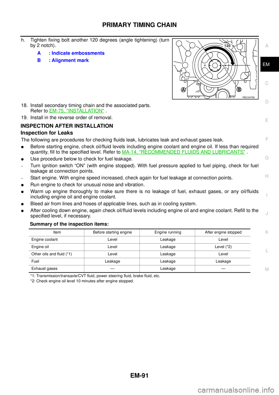
h. Tighten fixing bolt another 120 degrees (angle tightening) (turn
by 2 notch).
18. Install secondary timing chain and the associated parts.
Refer toEM-75, "
INSTALLATION".
19. Install in the reverse order of removal.
INSPECTION AFTER INSTALLATION
Inspection for Leaks
The following are procedures for checking fluids leak, lubricates leak and exhaust gases leak.
lBefore starting engine, check oil/fluid levels including engine coolant and engine oil. If less than required
quantity, fill to the specified level. Refer toMA-14, "
RECOMMENDED FLUIDS AND LUBRICANTS".
lUse procedure below to check for fuel leakage.
–Turn ignition switch “ON” (with engine stopped). With fuel pressure applied to fuel piping, check for fuel
leakage at connection points.
–Start engine. With engine speed increased, check again for fuel leakage at connection points.
lRun engine to check for unusual noise and vibration.
lWarm up engine thoroughly to make sure there is no leakage of fuel, exhaust gases, or any oil/fluids
including engine oil and engine coolant.
lBleed air from lines and hoses of applicable lines, such as in cooling system.
lAfter cooling down engine, again check oil/fluid levels including engine oil and engine coolant. Refill to the
specified level, if necessary.
Summary of the inspection items:
*1: Transmission/transaxle/CVT fluid, power steering fluid, brake fluid, etc.
*2: Check engine oil level 10 minutes after engine stopped.
A : Indicate embossments
B : Alignment mark
PBIC3476E
Item Before starting engine Engine running After engine stopped
Engine coolant Level Leakage Level
Engine oil Level Leakage Level (*2)
Other oils and fluid (*1) Level Leakage Level
Fuel Leakage Leakage Leakage
Exhaust gases — Leakage —