Page 2311 of 3171
MA-36
CHASSIS AND BODY MAINTENANCE
CALIPER
Check for any fluid leakage. Repair as necessary.
PA D
Check for any wear or damage. Repair or replace as necessary.
Checking Drum BrakeELS001K1
DRUM
Check the condition of the drum, and for any wear or damage.
Repair or replace as necessary.
WHEEL CYLINDER
lCheck for leakage.Standard thickness : 28.0 mm (1.12 in)
Repair limit thickness : 26.0 mm (1.024 in)
SMA260A
Standard thickness : 11.0 mm (0.43 in)
Repair limit thickness : 2.0 mm (0.08 in)
LMA051
Standard inner diameter : 295 mm (11.61 in) dia.
Repair limit inner diameter : 296.5 mm (11.67 in) dia.
SBR022A
SFIA0657J
Page 2597 of 3171

PG-68
HARNESS
Wiring Diagram Codes (Cell Codes)
EKS00LJ9
Use the chart below to find out what each wiring diagram code stands for.
Refer to the wiring diagram code in the alphabetical index to find the location (page number) of each wiring
diagram.
Code Section Wiring Diagram Name
A/C,A ATC Auto Air Conditioner
A/C,M MTC Manual Air Conditioner
ABS BRC Anti-lock Brake System
APP1PW EC Accelerator Pedal Position Sensor 1 Power
APP2PW EC Accelerator Pedal Position Sensor 2 Power
APPS1 EC Accelerator Pedal Position Sensor 1
APPS2 EC Accelerator Pedal Position Sensor 2
APPS3 EC Accelerator Pedal Position Sensor
ASC/BS EC ASCD Brake Switch
ASC/SW EC ASCD Steering Switch
ASCBOF EC ASCD Brake Switch
ASCIND EC ASCD Indicator
AT/IND DI A/T Indicator Lamp
AUDIO AV Audio
AUTO/L LT Auto Lignt System
BACK/L LT Back-up Lamp
BOOST EC Turbocharger Boost Sensor
CAN AT CAN Communication Line
CAN EC CAN Communication Line
CAN LAN CAN System
CHARGE SC Charging System
CHIME DI Warning Chime
CIGER WW Cigarette Lighter
CKPS EC Crankshaft Position Sensor
CMPS EC Camshaft Position Sensor
COMBSW LT Combination Switch
COMM AV Audio Visual Communication Line
COMPAS DI Compass
COOL/F EC Cooling Fan Control
D/LOCK BL Power Door Lock
DIFLOC RFD Rear Final Drive
DEF GW Rear Window Defogger
DTRL LT Headlamp — With Daytime Running Light System
ECMRLY EC ECM Relay
ECTS EC Engine Coolant Temperature Sensor
EGRVLV EC EGR Volume Control System
EMNT EC Electronic Controlled Engine Mount Control Solenoid Valve
F/FOG LT Front Fog Lamp
F/PUMP EC Fuel Pump
FRPS EC Fuel Rail Pressure Sensor
FTS AT A/T Fluid Temperature Sensor
Page 2632 of 3171

NOISE, VIBRATION, AND HARSHNESS (NVH) TROUBLESHOOTING
PS-5
C
D
E
F
H
I
J
K
L
MA
B
PS
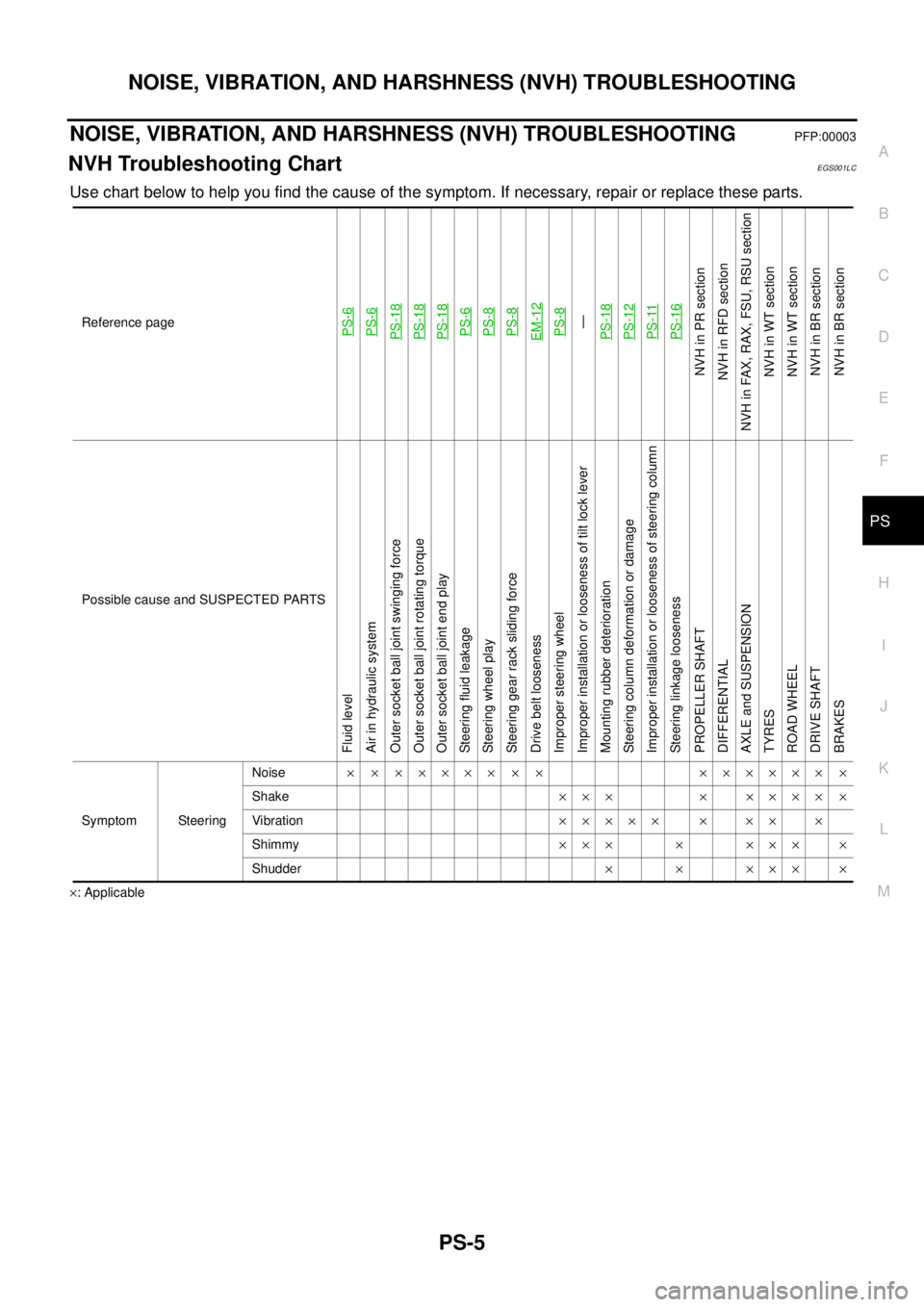
NOISE, VIBRATION, AND HARSHNESS (NVH) TROUBLESHOOTINGPFP:00003
NVH Troubleshooting ChartEGS001LC
Use chart below to help you find the cause of the symptom. If necessary, repair or replace these parts.
´: ApplicableReference page
PS-6PS-6PS-18PS-18PS-18PS-6PS-8PS-8EM-12PS-8—
PS-18PS-12PS-11PS-16
NVHinPRsection
NVH in RFD section
NVH in FAX, RAX, FSU, RSU section
NVH in WT section
NVH in WT section
NVHinBRsection
NVHinBRsection
Possible cause and SUSPECTED PARTS
Fluid level
Air in hydraulic system
Outer socket ball joint swinging force
Outer socket ball joint rotating torque
Outer socket ball joint end play
Steering fluid leakage
Steering wheel play
Steering gear rack sliding force
Drive belt looseness
Improper steering wheel
Improper installation or looseness of tilt lock lever
Mounting rubber deterioration
Steering column deformation or damage
Improper installation or looseness of steering column
Steering linkage looseness
PROPELLER SHAFT
DIFFERENTIAL
AXLE and SUSPENSION
TYRES
ROAD WHEEL
DRIVE SHAFT
BRAKES
Symptom SteeringNoise´ ´ ´´´´´ ´ ´ ´´´´´´ ´
Shake´´´ ´ ´´´´ ´
Vibration´´´´´ ´ ´´ ´
Shimmy´´´ ´ ´´´ ´
Shudder´ ´ ´´´ ´
Page 2635 of 3171

PS-8
STEERING WHEEL
STEERING WHEEL
PFP:48430
On-Vehicle Inspection and ServiceEGS001LG
CHECKING CONDITION OF INSTALLATION
lCheck installation conditions of steering gear assembly, front suspension assembly, axle and steering col-
umn assembly.
lCheck if movement exists when steering wheel is moved up and down, to the left and right and to the axial
direction.
lCheck steering gear assembly mounting bolts and nuts for looseness. Refer toPS-14, "COMPONENT".
CHECKING STEERING WHEEL PLAY
lTurn steering wheel so that front wheels come to the straight-ahead position. Start engine and lightly turn
steering wheel to the left and right until front wheels start to move. Measure steering wheel movement on
the outer circumference.
lWhen the measurement value is outside the standard value, check backlash for each joint of steering col-
umn assembly and installation condition of steering gear assembly.
CHECKING NEUTRAL POSITION STEERING WHEEL
lMake sure that steering gear assembly, steering column assembly and steering wheel are installed in the
correct position.
lPerform neutral position inspection after wheel alignment. Refer toFSU-7, "Front Wheel Alignment".
lSet vehicle to the straight-ahead position and confirm steering wheel is in the neutral position.
lLoosen outer socket lock nut and turn inner socket to left and right equally to make fine adjustment if
steering wheel is not in the neutral position.
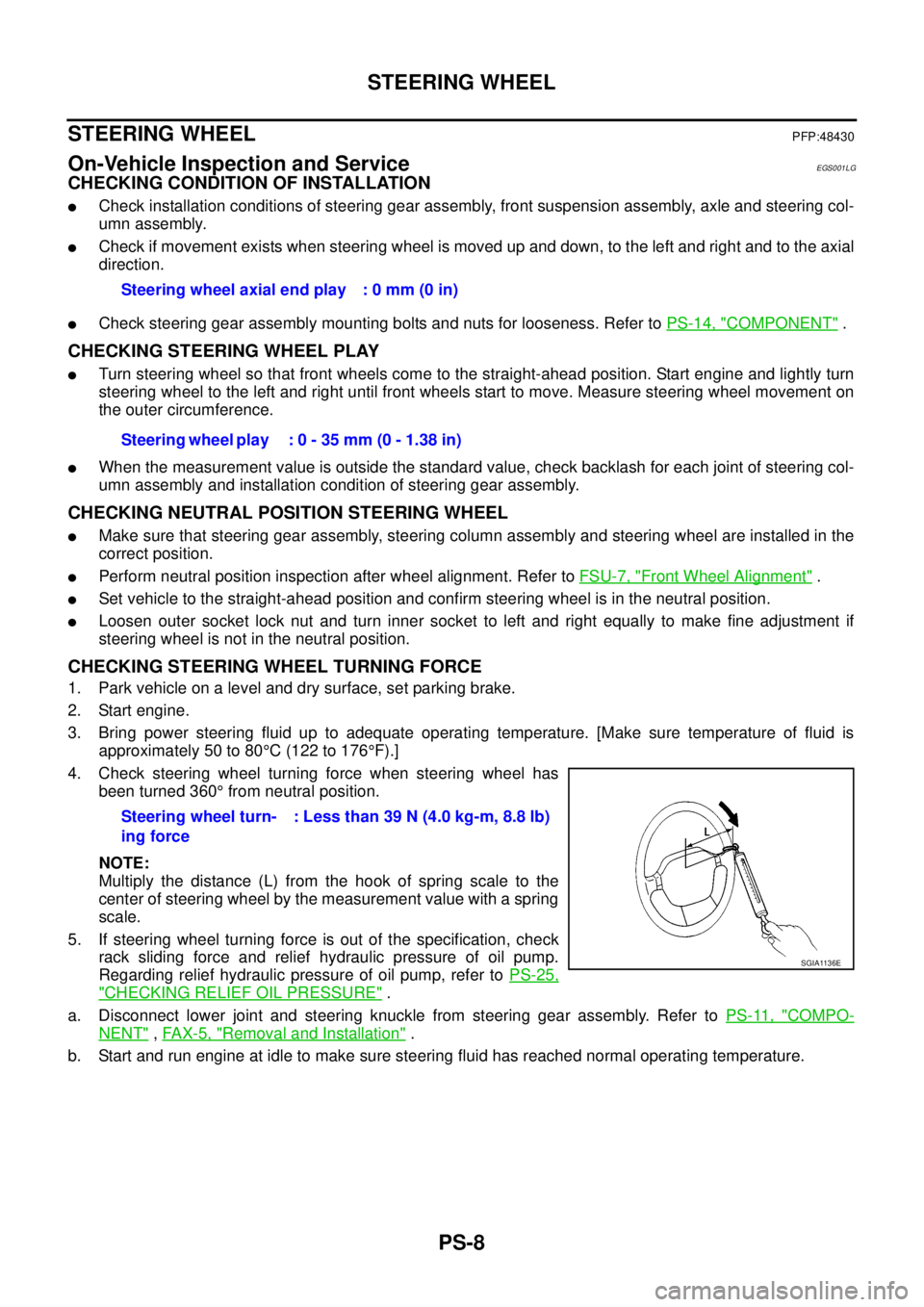
CHECKING STEERING WHEEL TURNING FORCE
1. Park vehicle on a level and dry surface, set parking brake.
2. Start engine.
3. Bring power steering fluid up to adequate operating temperature. [Make sure temperature of fluid is
approximately 50 to 80°C(122to176°F).]
4. Check steering wheel turning force when steering wheel has
been turned 360°from neutral position.
NOTE:
Multiply the distance (L) from the hook of spring scale to the
center of steering wheel by the measurement value with a spring
scale.
5. If steering wheel turning force is out of the specification, check
rack sliding force and relief hydraulic pressure of oil pump.
Regarding relief hydraulic pressure of oil pump, refer toPS-25,
"CHECKING RELIEF OIL PRESSURE".
a. Disconnect lower joint and steering knuckle from steering gear assembly. Refer toPS-11, "
COMPO-
NENT",FAX-5, "Removal and Installation".
b. Start and run engine at idle to make sure steering fluid has reached normal operating temperature.Steering wheel axial end play : 0 mm (0 in)
Steering wheel play : 0 - 35 mm (0 - 1.38 in)
Steering wheel turn-
ing force: Less than 39 N (4.0 kg-m, 8.8 lb)
SGIA1136E
Page 2717 of 3171
![NISSAN NAVARA 2005 Repair Workshop Manual RFD-14
[WITH LIMITED SLIP DIFFERENTIAL]
REAR FINAL DRIVE ASSEMBLY
REAR FINAL DRIVE ASSEMBLY
PFP:38300
Removal and InstallationEDS00398
REMOVAL
1. Remove the rear propeller shaft. Refer toPR-8, "Remova NISSAN NAVARA 2005 Repair Workshop Manual RFD-14
[WITH LIMITED SLIP DIFFERENTIAL]
REAR FINAL DRIVE ASSEMBLY
REAR FINAL DRIVE ASSEMBLY
PFP:38300
Removal and InstallationEDS00398
REMOVAL
1. Remove the rear propeller shaft. Refer toPR-8, "Remova](/manual-img/5/57362/w960_57362-2716.png)
RFD-14
[WITH LIMITED SLIP DIFFERENTIAL]
REAR FINAL DRIVE ASSEMBLY
REAR FINAL DRIVE ASSEMBLY
PFP:38300
Removal and InstallationEDS00398
REMOVAL
1. Remove the rear propeller shaft. Refer toPR-8, "Removal and Installation".
lPlug rear end of transmission or transfer.
2. Remove the axle shafts and back plate and torque members. Refer toRAX-7, "
Removal and Installation".
3. Disconnect the following components from the rear final drive.
lABS sensor wire harness
lRear cable (LH) and rear cable (RH)
lBrake hoses and brake tube
CAUTION:
Position the wire harness, cable and hoses away from the final drive assembly. Failure to do so
may result in components being damaged during rear axle assembly removal.
4. Support the rear final drive using a suitable jack.
5. Remove rear shock absorber lower bolts. Refer toRSU-6, "
Removal and Installation".
6. Remove leaf spring U-bolt nuts. Refer toRSU-7, "
Removal and Installation".
WARNING:
Support the rear final drive assembly using suitable jack before removing leaf spring U-bolt nuts.
7. Remove rear final drive assembly using suitable jack.
INSTALLATION
Installation is the reverse order of removal.
lWhen oil leaks while removing rear final drive assembly, check oil level after the installation. Refer to
RFD-9, "
Checking Differential Gear Oil".
lRefill brake fluid and bleed the air from the brake system. Refer toBR-11, "Bleeding Brake System".
Page 2784 of 3171
![NISSAN NAVARA 2005 Repair Workshop Manual REAR FINAL DRIVE ASSEMBLY
RFD-81
[WITH ELECTRONIC LOCKING DIFFERENTIAL]
C
E
F
G
H
I
J
K
L
MA
B
RFD
REAR FINAL DRIVE ASSEMBLYPFP:38300
Removal and InstallationEDS003BF
REMOVAL
1. Remove the rear propel NISSAN NAVARA 2005 Repair Workshop Manual REAR FINAL DRIVE ASSEMBLY
RFD-81
[WITH ELECTRONIC LOCKING DIFFERENTIAL]
C
E
F
G
H
I
J
K
L
MA
B
RFD
REAR FINAL DRIVE ASSEMBLYPFP:38300
Removal and InstallationEDS003BF
REMOVAL
1. Remove the rear propel](/manual-img/5/57362/w960_57362-2783.png)
REAR FINAL DRIVE ASSEMBLY
RFD-81
[WITH ELECTRONIC LOCKING DIFFERENTIAL]
C
E
F
G
H
I
J
K
L
MA
B
RFD
REAR FINAL DRIVE ASSEMBLYPFP:38300
Removal and InstallationEDS003BF
REMOVAL
1. Remove the rear propeller shaft. Refer toPR-8, "Removal and Installation".
lPlug rear end of transmission or transfer.
2. Remove the axle shafts and back plate and torque members. Refer toRAX-7, "
Removal and Installation".
3. Disconnect the following components from the rear final drive.
lABS sensor wire harness
lRear cable (LH) and rear cable (RH)
lBrake hoses and brake tube
lDifferential lock position switch harness connector
lDifferential lock solenoid harness connector
CAUTION:
Position the wire harness, cable and hoses away from the final drive assembly. Failure to do so
may result in components being damaged during rear axle assembly removal.
4. Support the rear final drive using a suitable jack.
5. Remove rear shock absorber lower bolts. Refer toRSU-6, "
Removal and Installation".
6. Remove leaf spring U-bolt nuts. Refer toRSU-7, "
Removal and Installation".
WARNING:
Support the rear final drive assembly using suitable jack before removing leaf spring U-bolt nuts.
7. Remove rear final drive assembly using suitable jack.
INSTALLATION
Installation is the reverse order of removal.
lWhen oil leaks while removing rear final drive assembly, check oil level after the installation. Refer to
RFD-40, "
Checking Differential Gear Oil".
lRefill brake fluid and bleed the air from the brake system. Refer toBR-11, "Bleeding Brake System".
lAfter the installation, check DIFF LOCK indicator lamp. Refer toRFD-33, "Precautions for Differential
Case Assembly and Differential Lock Control Unit Replacement".