Page 804 of 3171
BR-18
BRAKE MASTER CYLINDER
Disassembly and Assembly
EFS005SS
DISASSEMBLY
CAUTION:
lMaster cylinder assembly cannot be disassembled.
lRemove reservoir tank only when absolutely necessary.
Pull reservoir tank off master cylinder sub-assembly, then remove grommets from master cylinder sub-assem-
bly body.
ASSEMBLY
CAUTION:
lDo not use mineral oils such as kerosene, gasoline during the cleaning and assembly process.
lDo not drop parts. If a part is dropped, do not use it.
1. Apply brake fluid to the grommet and attach to the cylinder body.
2. Install reservoir tank onto the cylinder body.
Page 807 of 3171
BRAKE BOOSTER
BR-21
C
D
E
G
H
I
J
K
L
MA
B
BR
INSTALLATION
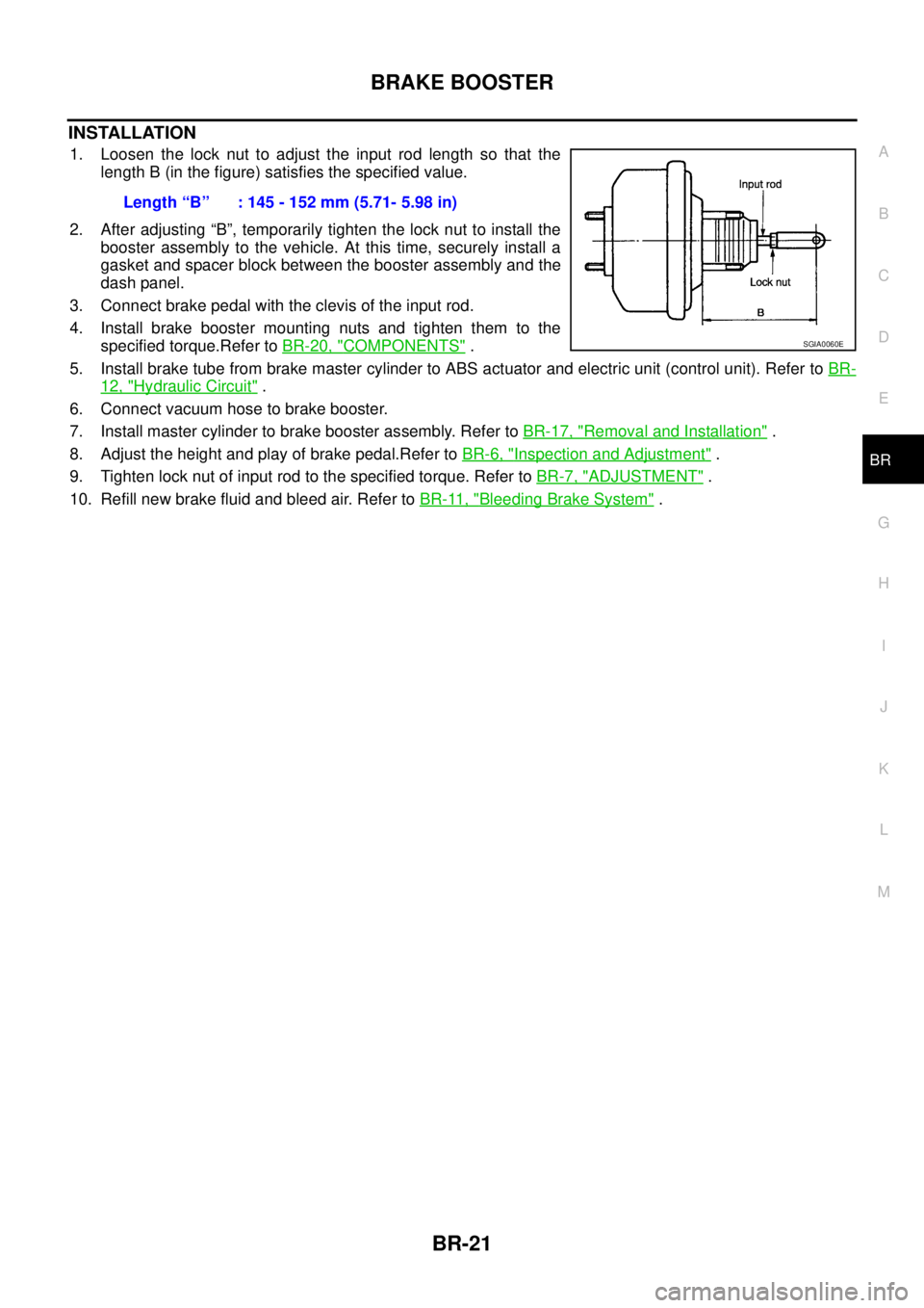
1. Loosen the lock nut to adjust the input rod length so that the
length B (in the figure) satisfies the specified value.
2. After adjusting “B”, temporarily tighten the lock nut to install the
booster assembly to the vehicle. At this time, securely install a
gasket and spacer block between the booster assembly and the
dash panel.
3. Connect brake pedal with the clevis of the input rod.
4. Install brake booster mounting nuts and tighten them to the
specified torque.Refer toBR-20, "
COMPONENTS".
5. Install brake tube from brake master cylinder to ABS actuator and electric unit (control unit). Refer toBR-
12, "Hydraulic Circuit".
6. Connect vacuum hose to brake booster.
7. Install master cylinder to brake booster assembly. Refer toBR-17, "
Removal and Installation".
8. Adjust the height and play of brake pedal.Refer toBR-6, "
Inspection and Adjustment".
9. Tighten lock nut of input rod to the specified torque. Refer toBR-7, "
ADJUSTMENT".
10. Refill new brake fluid and bleed air. Refer toBR-11, "
Bleeding Brake System". Length“B” :145-152mm(5.71-5.98in)
SGIA0060E
Page 811 of 3171
FRONT DISC BRAKE
BR-25
C
D
E
G
H
I
J
K
L
MA
B
BR
WARNING:
Clean dust on caliper and brake pad with a vacuum dust collector to minimize the hazard of air- borne
particles or other materials.
CAUTION:
lWhile removing cylinder body, do not depress brake pedal because piston will pop out.
lIt is not necessary to remove bolts on torque member and brake hose except for disassembly or
replacement of caliper assembly. In this case, hang cylinder body with a wire so as not to stretch
brake hose.
lDo not damage piston boot.
lIf any shim is subject to serious corrosion, replace it with a new one.
lAlways replace shim as a set when replacing brake pad.
lKeep rotor out of brake fluid.
Removal and Installation of Brake PadEFS005T0
REMOVAL
1. Remove tyre from vehicle.
2. Remove lower sliding pin bolt.
3. Hang cylinder body with a wire. Remove pad assembly and pad retainer from torque member.
CAUTION:
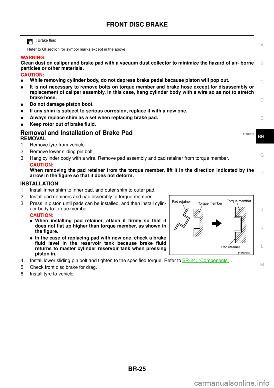
When removing the pad retainer from the torque member, lift it in the direction indicated by the
arrow in the figure so that it does not deform.
INSTALLATION
1. Install inner shim to inner pad, and outer shim to outer pad.
2. Install pad retainers and pad assembly to torque member.
3. Press in piston until pads can be installed, and then install cylin-
der body to torque member.
CAUTION:
lWhen installing pad retainer, attach it firmly so that it
does not flat up higher than torque member, as shown in
the figure.
lIn the case of replacing pad with new one, check a brake
fluid level in the reservoir tank because brake fluid
returns to master cylinder reservoir tank when pressing
piston in.
4. Install lower sliding pin bolt and tighten to the specified torque. Refer toBR-24, "
Components".
5. Check front disc brake for drag.
6. Install tyre to vehicle.
: Brake fluid
Refer to GI section for symbol marks except in the above.
PFIA0273E
Page 812 of 3171
BR-26
FRONT DISC BRAKE
Removal and Installation of Brake Caliper Assembly
EFS005T1
REMOVAL
1. Remove tyre from vehicle.
2. Fasten disc rotor using wheel nut.
CAUTION:
Align the matching marks of disc rotor and wheel hub, which were marked at the time of removal
when reusing disc rotor.
3. Drain brake fluid. Refer toBR-10, "
Drain and Refill".
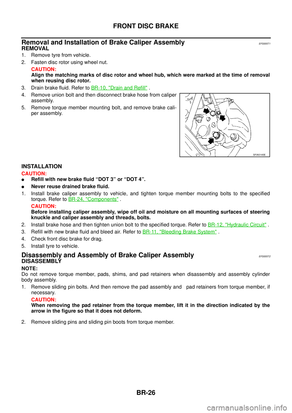
4. Remove union bolt and then disconnect brake hose from caliper
assembly.
5. Remove torque member mounting bolt, and remove brake cali-
per assembly.
INSTALLATION
CAUTION:
lRefill with new brake fluid “DOT 3” or “DOT 4”.
lNever reuse drained brake fluid.
1. Install brake caliper assembly to vehicle, and tighten torque member mounting bolts to the specified
torque. Refer toBR-24, "
Components".
CAUTION:
Before installing caliper assembly, wipe off oil and moisture on all mounting surfaces of steering
knuckle and caliper assembly and threads, bolts.
2. Install brake hose and then tighten union bolt to the specified torque. Refer toBR-12, "
Hydraulic Circuit".
3. Refill with new brake fluid and bleed air. Refer toBR-11, "
Bleeding Brake System".
4. Check front disc brake for drag.
5. Install tyre to vehicle.
Disassembly and Assembly of Brake Caliper AssemblyEFS005T2
DISASSEMBLY
NOTE:
Do not remove torque member, pads, shims, and pad retainers when disassembly and assembly cylinder
body assembly.
1. Remove sliding pin bolts. And then remove the pad assembly and pad retainers from torque member, if
necessary.
CAUTION:
When removing the pad retainer from the torque member, lift it in the direction indicated by the
arrow in the figure so that it does not deform.
2. Remove sliding pins and sliding pin boots from torque member.
SFIA0140E
Page 813 of 3171
FRONT DISC BRAKE
BR-27
C
D
E
G
H
I
J
K
L
MA
B
BR
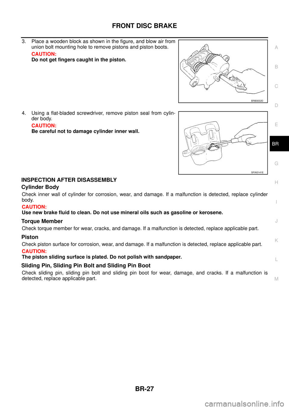
3. Place a wooden block as shown in the figure, and blow air from
union bolt mounting hole to remove pistons and piston boots.
CAUTION:
Do not get fingers caught in the piston.
4. Using a flat-bladed screwdriver, remove piston seal from cylin-
der body.
CAUTION:
Be careful not to damage cylinder inner wall.
INSPECTION AFTER DISASSEMBLY
Cylinder Body
Check inner wall of cylinder for corrosion, wear, and damage. If a malfunction is detected, replace cylinder
body.
CAUTION:
Use new brake fluid to clean. Do not use mineral oils such as gasoline or kerosene.
Torque Member
Check torque member for wear, cracks, and damage. If a malfunction is detected, replace applicable part.
Piston
Check piston surface for corrosion, wear, and damage. If a malfunction is detected, replace applicable part.
CAUTION:
The piston sliding surface is plated. Do not polish with sandpaper.
Sliding Pin, Sliding Pin Bolt and Sliding Pin Boot
Check sliding pin, sliding pin bolt and sliding pin boot for wear, damage, and cracks. If a malfunction is
detected, replace applicable part.
BRB0032D
SFIA0141E
Page 814 of 3171
BR-28
FRONT DISC BRAKE
ASSEMBLY
CAUTION:
When assembling, use only rubber lubricant specified below.
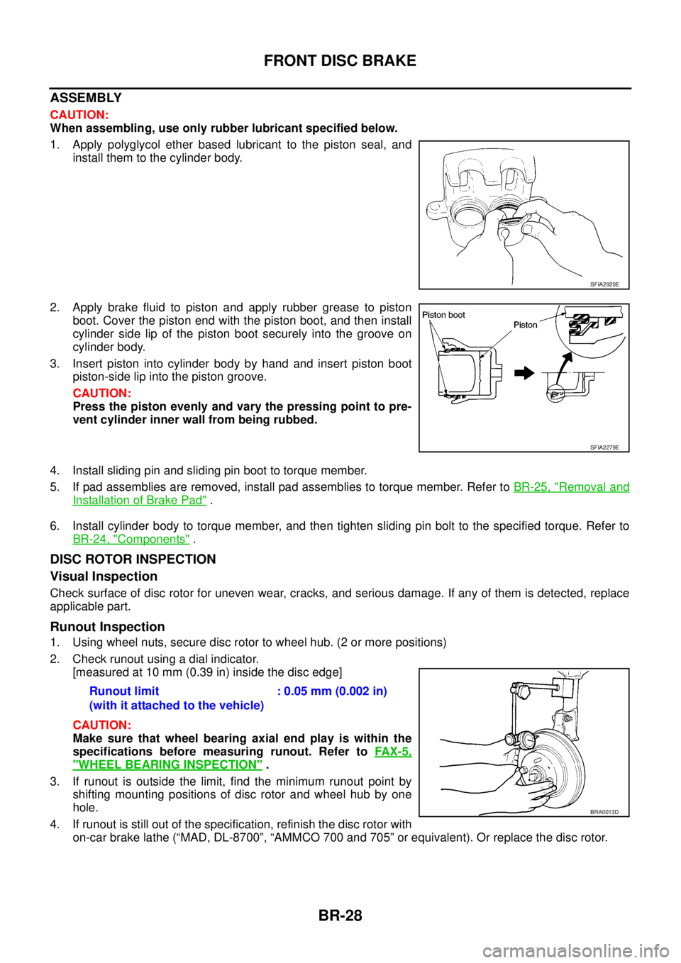
1. Apply polyglycol ether based lubricant to the piston seal, and
install them to the cylinder body.
2. Apply brake fluid to piston and apply rubber grease to piston
boot.Coverthepistonendwiththepistonboot,andtheninstall
cylinder side lip of the piston boot securely into the groove on
cylinder body.
3. Insert piston into cylinder body by hand and insert piston boot
piston-side lip into the piston groove.
CAUTION:
Press the piston evenly and vary the pressing point to pre-
vent cylinder inner wall from being rubbed.
4. Install sliding pin and sliding pin boot to torque member.
5. If pad assemblies are removed, install pad assemblies to torque member. Refer toBR-25, "
Removal and
Installation of Brake Pad".
6. Install cylinder body to torque member, and then tighten sliding pin bolt to the specified torque. Refer to
BR-24, "
Components".
DISC ROTOR INSPECTION
Visual Inspection
Check surface of disc rotor for uneven wear, cracks, and serious damage. If any of them is detected, replace
applicable part.
Runout Inspection
1. Using wheel nuts, secure disc rotor to wheel hub. (2 or more positions)
2. Check runout using a dial indicator.
[measured at 10 mm (0.39 in) inside the disc edge]
CAUTION:
Make sure that wheel bearing axial end play is within the
specifications before measuring runout. Refer toFAX-5,
"WHEEL BEARING INSPECTION".
3. If runout is outside the limit, find the minimum runout point by
shifting mounting positions of disc rotor and wheel hub by one
hole.
4. If runout is still out of the specification, refinish the disc rotor with
on-car brake lathe (“MAD, DL-8700”, “AMMCO 700 and 705” or equivalent). Or replace the disc rotor.
SFIA2920E
SFIA2279E
Runout limit
(with it attached to the vehicle):0.05mm(0.002in)
BRA0013D
Page 816 of 3171
BR-30
REAR DRUM BRAKE
REAR DRUM BRAKE
PFP:43206
ComponentsEFS006AF
WARNING:
Clean dust on drum and back plate with a vacuum dust collector to minimize the hazard of air borne
particles or other materials.
CAUTION:
Make sure parking brake lever is released completely.
1. Plug 2. Shoe hold pin 3. Back plate
4. Boot 5. Piston 6. Piston cup
7. Cap 8. Bleed valve 9. Wheel cylinder
10. Spring 11. Pin 12. Adjuster lever
13. Toggle lever 14. Adjuster 15. Conical washer
16. Shoe (trailing side) 17. Shoe (leading side) 18. Retainer ring
19. Retainer 20. Adjuster spring 21. Return spring (lower side)
22. Return spring (upper side) 23. Drum : Brake fluid
1: PBC (Poly Butyl Cuprysil) grease
or silicone-based grease2: Rubber grease 3: Polyglycol ether based lubricant
Refer to GI section for seasonal marks except in the above.
SFIA3199E
Page 818 of 3171
BR-32
REAR DRUM BRAKE
INSPECTION AFTER REMOVAL
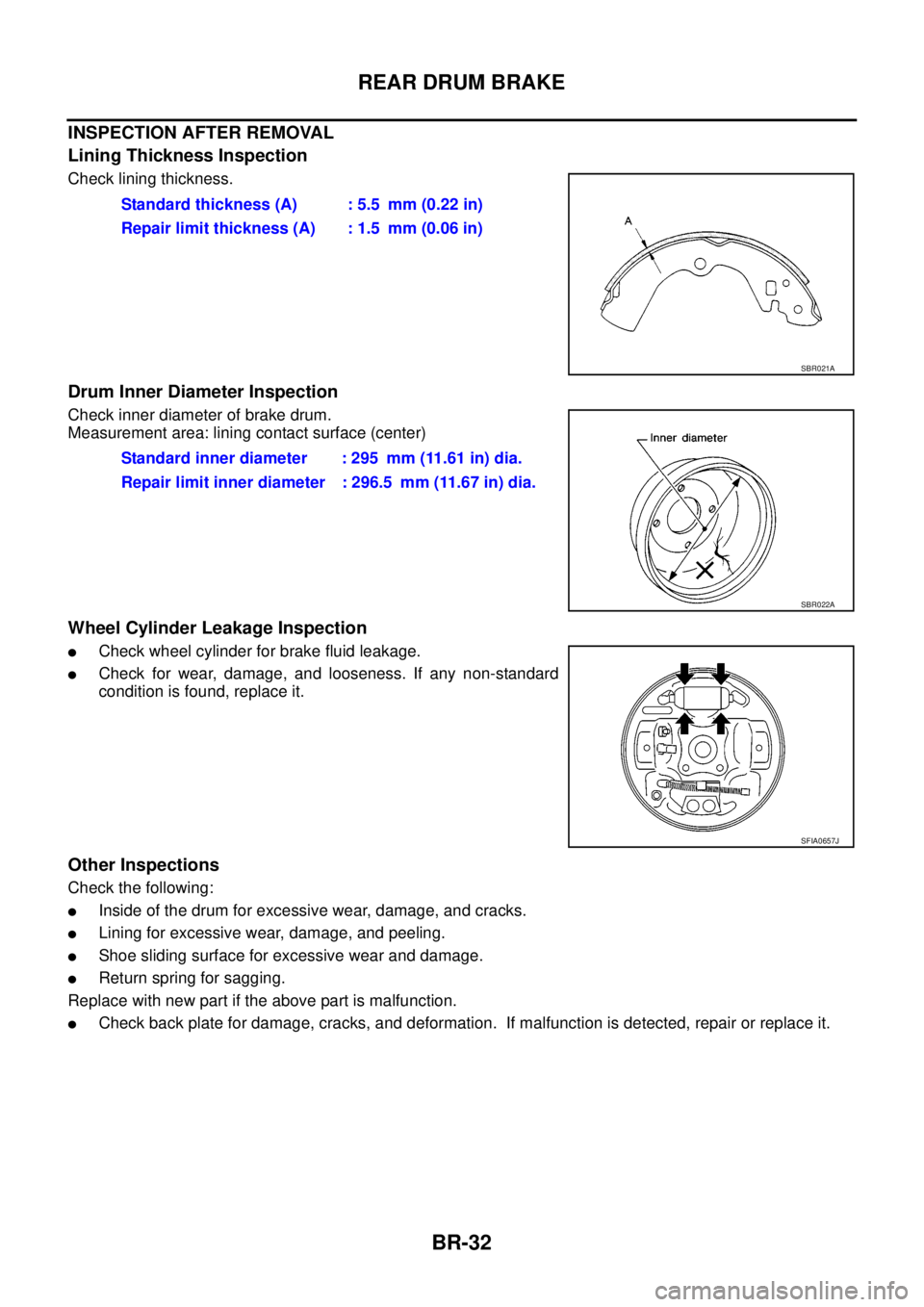
Lining Thickness Inspection
Check lining thickness.
Drum Inner Diameter Inspection
Check inner diameter of brake drum.
Measurement area: lining contact surface (center)
Wheel Cylinder Leakage Inspection
lCheck wheel cylinder for brake fluid leakage.
lCheck for wear, damage, and looseness. If any non-standard
condition is found, replace it.
Other Inspections
Check the following:
lInside of the drum for excessive wear, damage, and cracks.
lLining for excessive wear, damage, and peeling.
lShoe sliding surface for excessive wear and damage.
lReturn spring for sagging.
Replace with new part if the above part is malfunction.
lCheck back plate for damage, cracks, and deformation. If malfunction is detected, repair or replace it.Standard thickness (A) : 5.5 mm (0.22 in)
Repair limit thickness (A) : 1.5 mm (0.06 in)
SBR021A
Standard inner diameter : 295 mm (11.61 in) dia.
Repair limit inner diameter : 296.5 mm (11.67 in) dia.
SBR022A
SFIA0657J