Page 79 of 3171
TROUBLE DIAGNOSIS
AT-71
D
E
F
G
H
I
J
K
L
MA
B
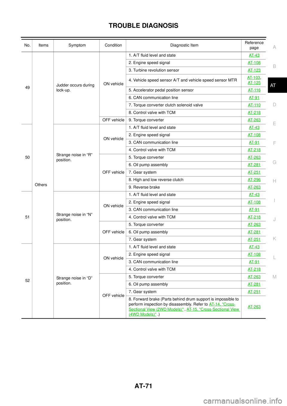
AT49
OthersJudder occurs during
lock-up.ON vehicle1. A/T fluid level and stateAT- 4 3
2. Engine speed signalAT-108
3. Turbine revolution sensorAT-123
4. Vehicle speed sensor A/T and vehicle speed sensor MTRAT-103,
AT-125
5. Accelerator pedal position sensorAT- 11 6
6. CAN communication lineAT- 9 1
7. Torque converter clutch solenoid valveAT- 11 0
8. Control valve with TCMAT-218
OFF vehicle 9. Torque converterAT-263
50Strange noise in “R”
position.ON vehicle1. A/T fluid level and stateAT- 4 3
2. Engine speed signalAT-108
3. CAN communication lineAT- 9 1
4. Control valve with TCMAT-218
OFF vehicle5. Torque converterAT-263
6. Oil pump assemblyAT-281
7. Gear systemAT-251
8. High and low reverse clutchAT-296
9. Reverse brakeAT-263
51Strange noise in “N”
position.ON vehicle1. A/T fluid level and stateAT- 4 3
2. Engine speed signalAT-108
3. CAN communication lineAT- 9 1
4. Control valve with TCMAT-218
OFF vehicle5. Torque converterAT-2636. Oil pump assemblyAT-281
7. Gear systemAT-251
52Strange noise in “D”
position.ON vehicle1. A/T fluid level and stateAT- 4 3
2. Engine speed signalAT-108
3. CAN communication lineAT- 9 1
4. Control valve with TCMAT-218
OFF vehicle5. Torque converterAT-263
6. Oil pump assemblyAT-281
7. Gear systemAT-251
8. Forward brake (Parts behind drum support is impossible to
perform inspection by disassembly. Refer toAT-14, "
Cross-
Sectional View (2WD Models)",AT- 1 5 , "Cross-Sectional View
(4WD Models)".)AT-263
No. Items Symptom Condition Diagnostic ItemReference
page
Page 80 of 3171
AT-72
TROUBLE DIAGNOSIS
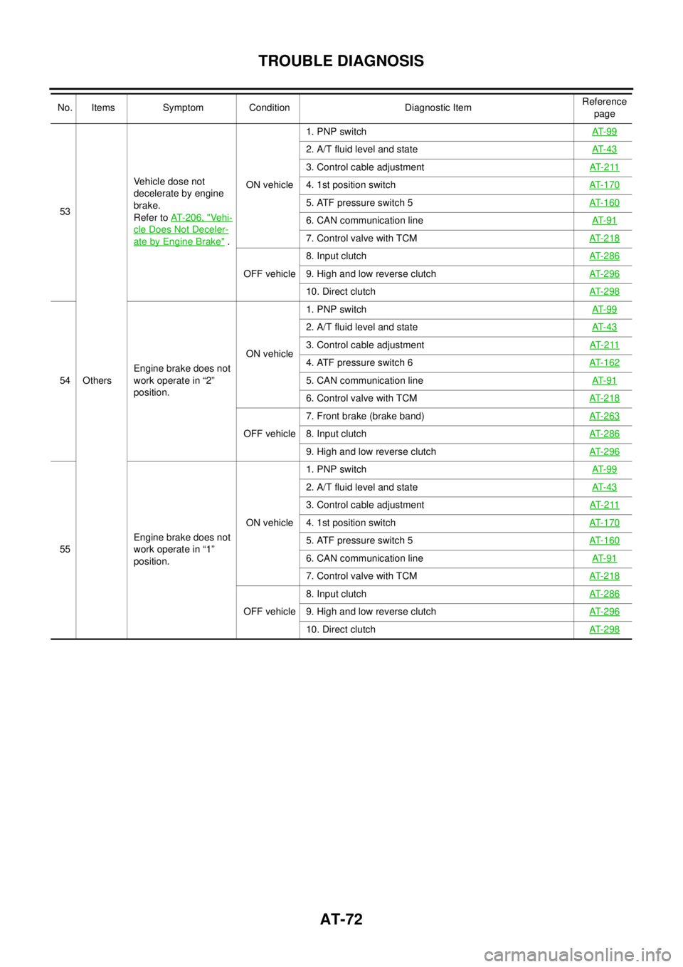
53
OthersVehicle dose not
decelerate by engine
brake.
Refer toAT-206, "Vehi-
cle Does Not Deceler-
ate by Engine Brake".ON vehicle1. PNP switchAT- 9 9
2. A/T fluid level and stateAT- 4 3
3. Control cable adjustmentAT- 2 11
4. 1st position switchAT- 1 7 0
5. ATF pressure switch 5AT- 1 6 0
6. CAN communication lineAT- 9 1
7. Control valve with TCMAT- 2 1 8
OFF vehicle8. Input clutchAT- 2 8 69. High and low reverse clutchAT- 2 9 6
10. Direct clutchAT- 2 9 8
54Engine brake does not
work operate in “2”
position.ON vehicle1. PNP switchAT- 9 9
2. A/T fluid level and stateAT- 4 3
3. Control cable adjustmentAT- 2 11
4. ATF pressure switch 6AT- 1 6 2
5. CAN communication lineAT- 9 1
6. Control valve with TCMAT- 2 1 8
OFF vehicle7. Front brake (brake band)AT- 2 6 38. Input clutchAT- 2 8 6
9. High and low reverse clutchAT- 2 9 6
55Engine brake does not
work operate in “1”
position.ON vehicle1. PNP switchAT- 9 9
2. A/T fluid level and stateAT- 4 3
3. Control cable adjustmentAT- 2 11
4. 1st position switchAT- 1 7 0
5. ATF pressure switch 5AT- 1 6 0
6. CAN communication lineAT- 9 1
7. Control valve with TCMAT- 2 1 8
OFF vehicle8. Input clutchAT- 2 8 69. High and low reverse clutchAT- 2 9 6
10. Direct clutchAT- 2 9 8
No. Items Symptom Condition Diagnostic ItemReference
page
Page 81 of 3171
TROUBLE DIAGNOSIS
AT-73
D
E
F
G
H
I
J
K
L
MA
B
AT
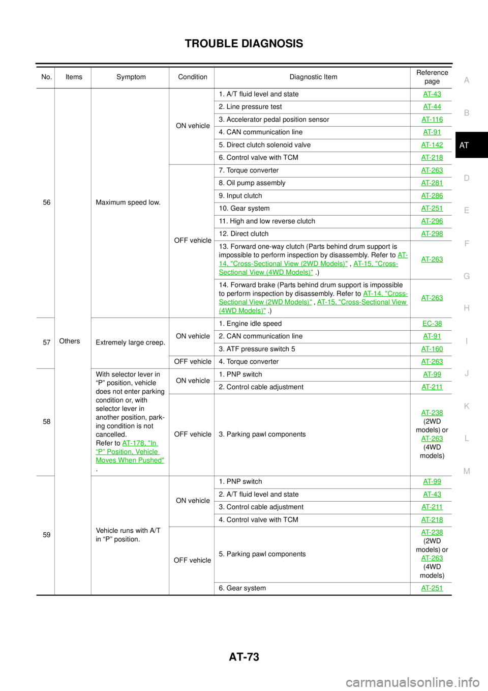
56
OthersMaximum speed low.ON vehicle1. A/T fluid level and stateAT- 4 3
2. Line pressure testAT- 4 4
3. Accelerator pedal position sensorAT- 11 6
4. CAN communication lineAT- 9 1
5. Direct clutch solenoid valveAT-142
6. Control valve with TCMAT-218
OFF vehicle7. Torque converterAT-263
8. Oil pump assemblyAT-281
9. Input clutchAT-286
10. Gear systemAT-251
11. High and low reverse clutchAT-296
12. Direct clutchAT-298
13. Forward one-way clutch (Parts behind drum support is
impossible to perform inspection by disassembly. Refer toAT-
14, "Cross-Sectional View (2WD Models)",AT- 1 5 , "Cross-
SectionalView(4WDModels)".)AT-263
14. Forward brake (Parts behind drum support is impossible
to perform inspection by disassembly. Refer toAT- 1 4 , "
Cross-
Sectional View (2WD Models)",AT- 1 5 , "Cross-Sectional View
(4WD Models)".)AT-263
57 Extremely large creep.ON vehicle1. Engine idle speedEC-382. CAN communication lineAT- 9 1
3. ATF pressure switch 5AT-160
OFF vehicle 4. Torque converterAT-263
58With selector lever in
“P” position, vehicle
does not enter parking
condition or, with
selector lever in
another position, park-
ing condition is not
cancelled.
Refer toAT-178, "
In
“P”Position, Vehicle
Moves When Pushed"
.ON vehicle1. PNP switchAT- 9 9
2. Control cable adjustmentAT- 2 11
OFF vehicle 3. Parking pawl componentsAT-238
(2WD
models) or
AT-263
(4WD
models)
59VehiclerunswithA/T
in “P” position.ON vehicle1. PNP switchAT- 9 9
2. A/T fluid level and stateAT- 4 3
3. Control cable adjustmentAT- 2 11
4. Control valve with TCMAT-218
OFF vehicle5. Parking pawl componentsAT-238
(2WD
models) or
AT-263
(4WD
models)
6. Gear systemAT-251
No. Items Symptom Condition Diagnostic ItemReference
page
Page 82 of 3171
AT-74
TROUBLE DIAGNOSIS
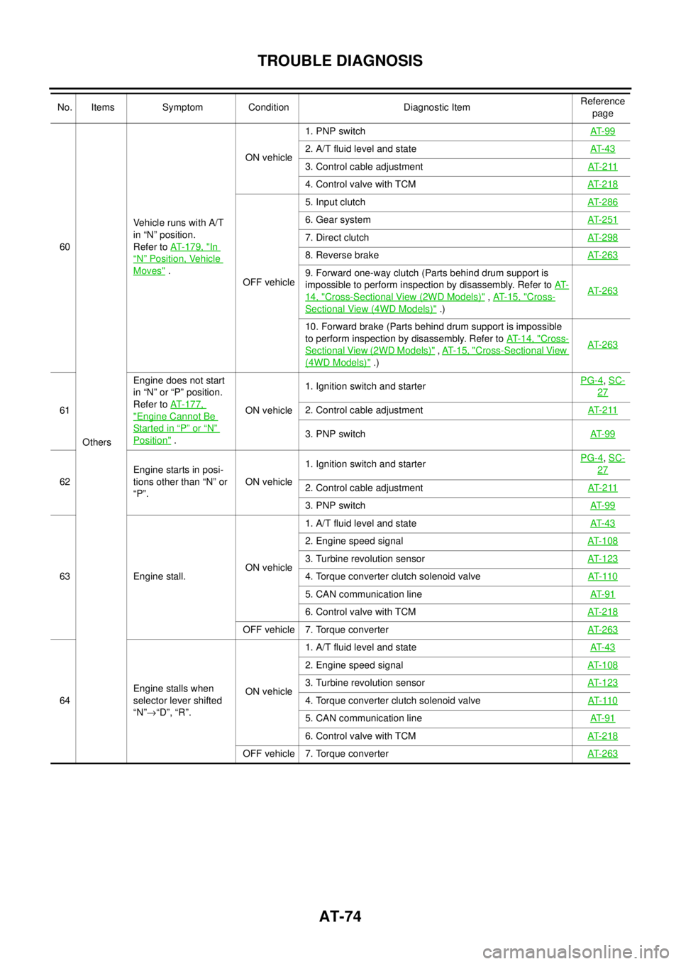
60
OthersVehicle runs with A/T
in “N” position.
Refer toAT-179, "In
“N”Position, Vehicle
Moves".ON vehicle1. PNP switchAT- 9 9
2. A/T fluid level and stateAT- 4 3
3. Control cable adjustmentAT- 2 11
4. Control valve with TCMAT- 2 1 8
OFF vehicle5. Input clutchAT- 2 8 6
6. Gear systemAT- 2 5 1
7. Direct clutchAT- 2 9 8
8. Reverse brakeAT- 2 6 3
9. Forward one-way clutch (Parts behind drum support is
impossible to perform inspection by disassembly. Refer toAT-
14, "Cross-Sectional View (2WD Models)",AT- 1 5 , "Cross-
Sectional View (4WD Models)".)AT- 2 6 3
10. Forward brake (Parts behind drum support is impossible
to perform inspection by disassembly. Refer toAT-14, "
Cross-
Sectional View (2WD Models)",AT-15, "Cross-Sectional View
(4WD Models)".)AT- 2 6 3
61Engine does not start
in“N”or“P”position.
Refer toAT-177,"Engine Cannot Be
Started in“P”or“N”
Position".ON vehicle1. Ignition switch and starterPG-4
,SC-
27
2. Control cable adjustmentAT- 2 11
3. PNP switchAT- 9 9
62Engine starts in posi-
tions other than “N” or
“P”.ON vehicle1. Ignition switch and starterPG-4
,SC-
27
2. Control cable adjustmentAT- 2 11
3. PNP switchAT- 9 9
63 Engine stall.ON vehicle1. A/T fluid level and stateAT- 4 3
2. Engine speed signalAT- 1 0 8
3. Turbine revolution sensorAT- 1 2 3
4. Torque converter clutch solenoid valveAT- 11 0
5. CAN communication lineAT- 9 1
6. Control valve with TCMAT- 2 1 8
OFF vehicle 7. Torque converterAT- 2 6 3
64Engine stalls when
selector lever shifted
“N”®“D”, “R”.ON vehicle1. A/T fluid level and stateAT- 4 3
2. Engine speed signalAT- 1 0 8
3. Turbine revolution sensorAT- 1 2 3
4. Torque converter clutch solenoid valveAT- 11 0
5. CAN communication lineAT- 9 1
6. Control valve with TCMAT- 2 1 8
OFF vehicle 7. Torque converterAT- 2 6 3
No. Items Symptom Condition Diagnostic ItemReference
page
Page 83 of 3171
TROUBLE DIAGNOSIS
AT-75
D
E
F
G
H
I
J
K
L
MA
B
AT
65 OthersEngine speed does not
return to idle.
Refer toAT-199,
"Engine Speed Does
Not Return to Idle".ON vehicle1. A/T fluid level and stateAT- 4 3
2. ATF pressure switch 5 and direct clutch solenoid valveAT-160,
AT-142
3. ATF pressure switch 1 and front brake solenoid valveAT-156,
AT-137
4. Accelerator pedal position sensorAT- 11 6
5. Vehicle speed sensor A/T and vehicle speed sensor MTRAT-103,
AT-125
6. CAN communication lineAT- 9 1
7. Control valve with TCMAT-218
OFF vehicle8. Front brake (brake band)AT-2639. Direct clutchAT-298
No. Items Symptom Condition Diagnostic ItemReference
page
Page 98 of 3171
AT-90
TROUBLE DIAGNOSIS
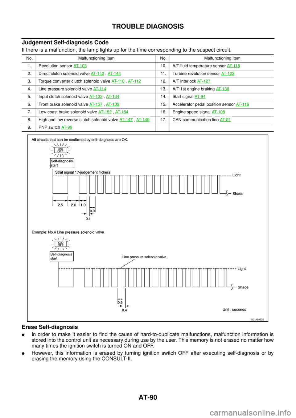
Judgement Self-diagnosis Code
If there is a malfunction, the lamp lights up for the time corresponding to the suspect circuit.
Erase Self-diagnosis
lIn order to make it easier to find the cause of hard-to-duplicate malfunctions, malfunction information is
stored into the control unit as necessary during use by the user. This memory is not erased no matter how
many times the ignition switch is turned ON and OFF.
lHowever, this information is erased by turning ignition switch OFF after executing self-diagnosis or by
erasing the memory using the CONSULT-II.
No. Malfunctioning item No. Malfunctioning item
1. Revolution sensorAT- 1 0 3
10. A/T fluid temperature sensorAT- 11 8
2. Direct clutch solenoid valveAT- 1 4 2,AT-14411. Turbine revolution sensorAT- 1 2 3
3. Torque converter clutch solenoid valveAT- 11 0,AT- 11 212. A/T interlockAT-127
4. Line pressure solenoid valveAT- 11 413. A/T 1st engine brakingAT-130
5. Input clutch solenoid valveAT- 1 3 2,AT- 1 3 414. Start signalAT- 9 4
6. Front brake solenoid valveAT-137,AT- 1 3 915. Accelerator pedal position sensorAT- 11 6
7. Low coast brake solenoid valveAT- 1 5 2,AT- 1 5 416. Engine speed signalAT-108
8. High and low reverse clutch solenoid valveAT-147,AT- 1 4 917. CAN communication lineAT- 9 1
9. PNP switchAT- 9 9
SCIA6862E
Page 139 of 3171

DTC P1731 A/T 1ST ENGINE BRAKING
AT-131
D
E
F
G
H
I
J
K
L
MA
B
AT
Diagnostic ProcedureECS00FZP
1.CHECK INPUT SIGNALS
With CONSULT-II
1. Start the engine.
2. Select “SELECTION FROM MENU” in “DATA MONITOR” mode
for “A/T” with CONSULT-II.
3. Drive vehicle in the “1 ” position (1st gear), and confirm the ON/
OFF actuation of “ATF PRES SW 2” and “ON OFF SOL”.
OK or NG
OK >> GO TO 4.
NG >> GO TO 2.
2.CHECK TCM POWER SUPPLY AND GROUND CIRCUIT
Check TCM power supply and ground circuit. Refer toAT- 1 6 4 , "
MAIN POWER SUPPLY AND GROUND CIR-
CUIT".
OK or NG
OK >> GO TO 3.
NG >> Repair or replace damaged parts.
3.DETECT MALFUNCTIONING ITEM
Check the following.
lA/T assembly harness connector pin terminals for damage or loose connection with harness connector.
OK or NG
OK >> Replace control valve with TCM. Refer toAT- 2 1 8 , "Control Valve With TCM and A/T Fluid Temper-
ature Sensor 2".
NG >> Repair or replace damaged parts.
4.CHECK DTC
PerformAT- 1 3 0 , "
DTC Confirmation Procedure".
OK or NG
OK >>INSPECTION END
NG >> GO TO 2.
Item name Condition Display value
ON OFF SOLLow coast brake engaged. Refer toAT- 1 7
.ON
Low coast brake disengaged. Refer toAT- 1 7
.OFF
AT F P R E S S W 2Low coast brake engaged. Refer toAT- 1 7
.ON
Low coast brake disengaged. Refer toAT- 1 7
.OFF
SCIA4670E
Page 146 of 3171
AT-138
DTC P1757 FRONT BRAKE SOLENOID VALVE
Diagnostic Procedure
ECS00G07
1.CHECK INPUT SIGNAL
With CONSULT-II
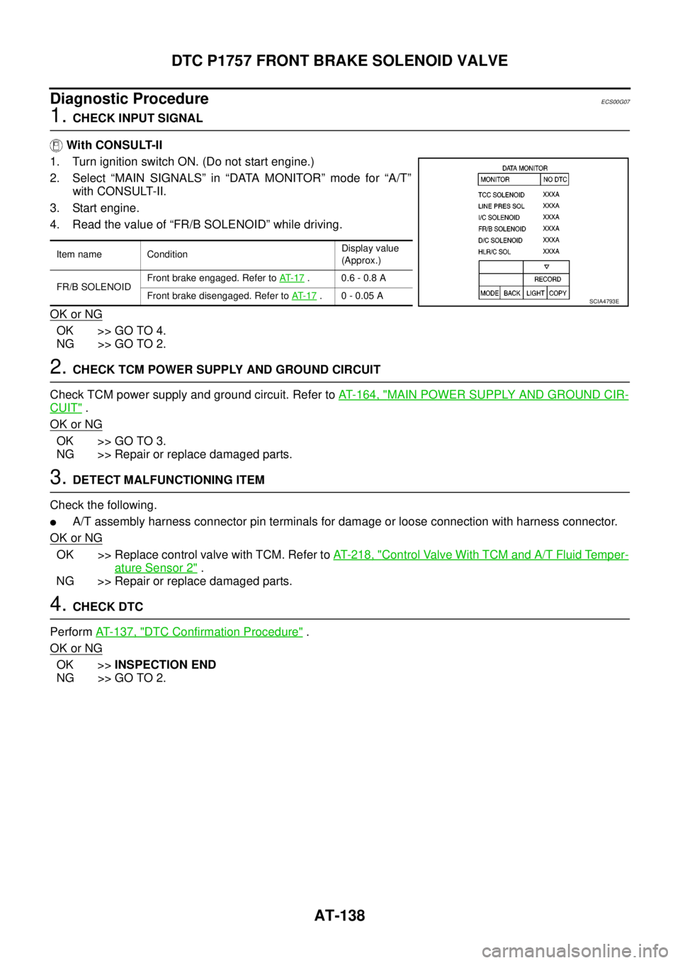
1. Turn ignition switch ON. (Do not start engine.)
2. Select “MAIN SIGNALS” in “DATA MONITOR” mode for “A/T”
with CONSULT-II.
3. Start engine.
4. Read the value of “FR/B SOLENOID” while driving.
OK or NG
OK >> GO TO 4.
NG >> GO TO 2.
2.CHECK TCM POWER SUPPLY AND GROUND CIRCUIT
Check TCM power supply and ground circuit. Refer toAT- 1 6 4 , "
MAIN POWER SUPPLY AND GROUND CIR-
CUIT".
OK or NG
OK >> GO TO 3.
NG >> Repair or replace damaged parts.
3.DETECT MALFUNCTIONING ITEM
Check the following.
lA/T assembly harness connector pin terminals for damage or loose connection with harness connector.
OK or NG
OK >> Replace control valve with TCM. Refer toAT- 2 1 8 , "Control Valve With TCM and A/T Fluid Temper-
ature Sensor 2".
NG >> Repair or replace damaged parts.
4.CHECK DTC
PerformAT- 1 3 7 , "
DTC Confirmation Procedure".
OK or NG
OK >>INSPECTION END
NG >> GO TO 2.
Item name ConditionDisplay value
(Approx.)
FR/B SOLENOIDFront brake engaged. Refer toAT- 1 7
. 0.6 - 0.8 A
Front brake disengaged. Refer toAT- 1 7
.0-0.05ASCIA4793E