2005 MITSUBISHI 380 sensor
[x] Cancel search: sensorPage 1216 of 1500
PARKING BRAKE LINING AND DRUM
PARKING BRAKES36-9
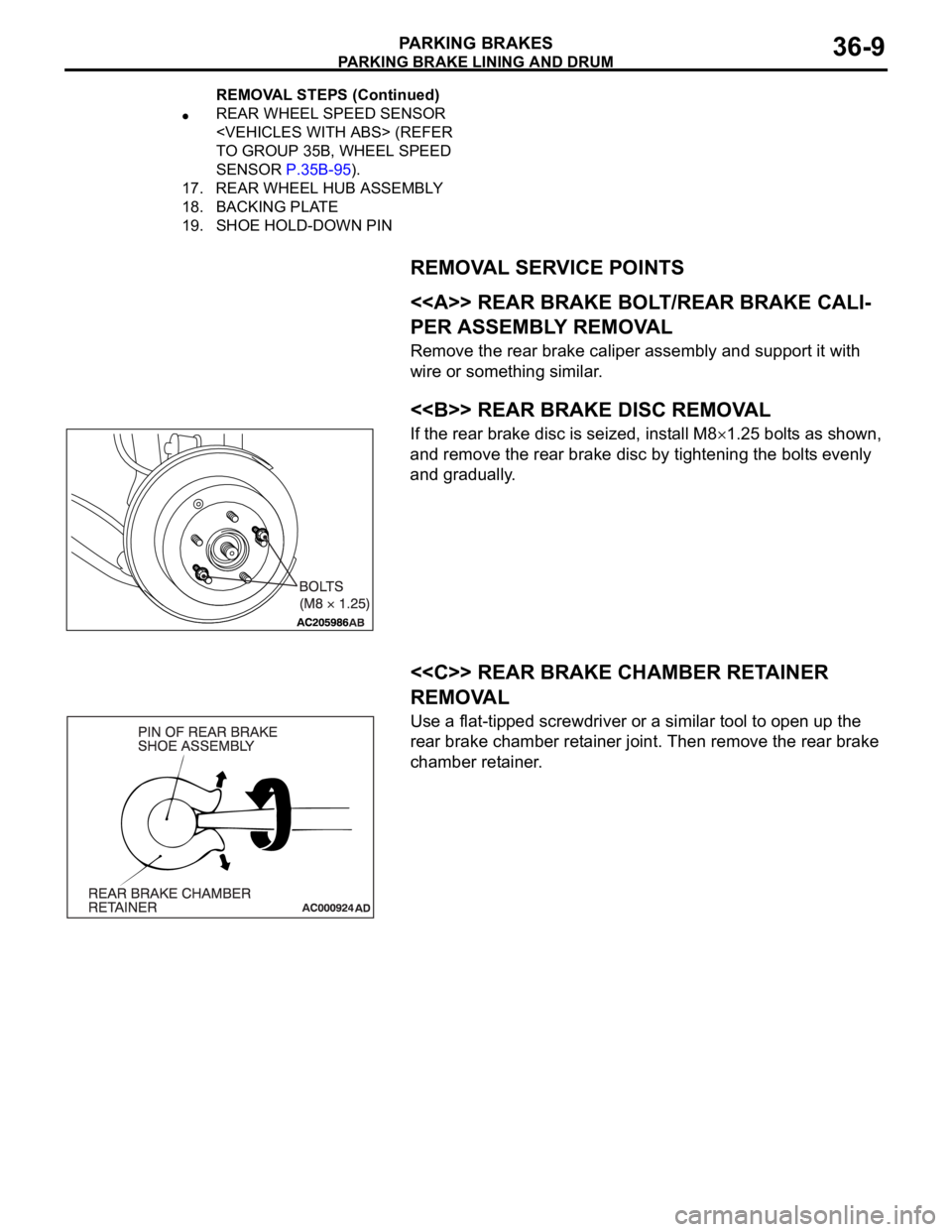
REMOVAL SERVICE POINTS
.
<> REAR BRAKE BOLT/REAR BRAKE CALI-
PER ASSEMBLY REMOVAL
Remove the rear brake caliper assembly and support it with
wire or something similar.
.
<> REAR BRAKE DISC REMOVAL
If the rear brake disc is seized, install M81.25 bolts as shown,
and remove the rear brake disc by tightening the bolts evenly
and gradually.
.
<
REMOVAL
Use a flat-tipped screwdriver or a similar tool to open up the
rear brake chamber retainer joint. Then remove the rear brake
chamber retainer.
REAR WHEEL SPEED SENSOR
TO GROUP 35B, WHEEL SPEED
SENSOR P.35B-95).
17. REAR WHEEL HUB ASSEMBLY
18. BACKING PLATE
19. SHOE HOLD-DOWN PIN
REMOVAL STEPS (Continued)
Page 1228 of 1500
HOW TO USE TROUBLESHOOTING/INSPECTION SERVICE POINTS
GENERAL00-7
HOW TO USE TROUBLESHOOTING/INSPECTION SERVICE
POINTS
TROUBLESHOOTING CONTENTSM1001013300062
During diagnosis, a DTC code associated with
other system may be set when the ignition
switch is turned on with connector(s) discon-
nected. On completion, confirm all systems
for DTC code(s). If DTC code(s) are set, erase
them all.
When the DIAGNOSTIC TOOL (MUT-III)
detects a diagnostic trouble code, its display
informs users whether a mechanical problem
currently exists (“current trouble”) or whether
it existed before but normal operation has
been restored (“past trouble”). However, if an
MPI, TPMS or SRS airbag-related DTC is set,
“Active DTC/Stored DTC” is not displayed. In
this case, follow the diagnosis procedure for
current trouble.
If a trouble, detected in a CAN communica-
tion-capable system, can be reproduced,
diagnose the CAN bus lines (Refer to GROUP
54C, Can Bus Line Diagnostics Chart
P.54C-15 or P.54C-15).
Troubleshooting of electronic control systems for
which the MUT -III can be used follows the basic out-
line described below. Even in systems for which the
MUT-III cannot be used, part of these systems still
follow this outline.
1. STANDARD FLOW OF DIAGNOSTIC
TROUBLESHOOTING
Troubleshooting strategy is shown in each group.
2. SYSTEM OPERATION AND SYMPTOM
VERIFICATION TESTS
If verification of the symptom(s) is difficult, proce-
dures for checking operation and verifying symptoms
are shown.
3. DIAGNOSTIC FUNCTION
The following trouble code diagnoses are shown.
How to read diagnostic trouble codes
How to erase diagnostic trouble codes
Input inspection service points
4. DIAGNOSTIC TROUBLE CODE CHART
If the MUT-III displays a diagnostic trouble code, find
the applicable inspection procedure according to this
chart.
5. SYMPTOM CHART
If there are symptoms, even though the MUT-III
shows that no DTCs are set, inspection procedures
for each symptom will be found by using this chart.
6. DIAGNOSTIC TROUBLE CODE
PROCEDURES
Indicates the inspection procedures corresponding to
each diagnostic trouble code. (Refer to P.00-9).
7. SYMPTOM PROCEDURES
Indicates the inspection procedures corresponding to
each symptom listed in the Symptom Chart (Refer to
P.00-9).
8. SERVICE DATA REFERENCE TABLE
Inspection items and normal judgment values have
been provided in this chart as reference information.
9. CHECK AT ECU TERMINALS
Terminal numbers for the ECU connectors, inspec-
tion items, and standard values have been provided
in this chart as reference information.
.
TERMINAL VOLTAGE CHECKS
1. Use correct tool to check each pin location on the
ENGINE-ECU Check harnes MB992044 and
measure with voltmeter.
Short-circuiting the positive (+) test probe
between a connector terminal and ground could
damage the vehicle wiring, the sensor, the ECU,
or all three. Use care to prevent this!
2. Insert the correct terminal tool into each of the
ENGINE-ECU check harness connector
terminals, and measure the voltage while referring
to the check chart.
NOTE: Measure voltage with the ECU connectors
connected.
You may find it convenient to pull out the ECU to
make it easier to connect the ENGINE-ECU check
harness.
Page 1229 of 1500

HOW TO USE TROUBLESHOOTING/INSPECTION SERVICE POINTS
GENERAL00-8
Checks don't have to be carried out in the order
given in the chart.
3. If voltage readings differ from normal condition
values, check related sensors, actuators, and
wiring. Replace or repair as needed.
4. After repair or replacement, recheck with the
voltmeter to confirm that the repair has corrected
the problem.
.
TERMINAL RESISTANCE AND
CONTINUITY CHECKS
1. Turn the ignition switch to the “LOCK” (OFF)
position.
2. Disconnect the ECU connector.
If resistance and continuity checks are per-
formed on the wrong terminals, damage to the
vehicle wiring, sensors, ECU, and/or ohmmeter
may occur. Use care to prevent this!
3. Measure the resistance and check for continuity
between the terminals of the ENGIN-ECU check
harness MB992044 connector while referring to
the check chart.
NOTE: Checks don't have to be carried out in the
order given in the chart.
4. If the ohmmeter shows any deviation from the
Normal Condition value, check the corresponding
sensor, actuator and related electrical wiring, then
repair or replace.
5. After repair or replacement, recheck with the
ohmmeter to confirm that the repair has corrected
the problem.
10. INSPECTION PROCEDURES USING
AN OSCILLOSCOPE
When there are inspection procedures using an
oscilloscope, these are listed.
Page 1236 of 1500
HOW TO USE TROUBLESHOOTING/INSPECTION SERVICE POINTS
GENERAL00-15
4. VERIFY THE INTERMITTENT MALFUNCTION IS
ELIMINATED
Repair the malfunctioning part and try to duplicate the condi-
tion(s) again to verify the intermittent malfunction has been
eliminated.
.
SIMULATION TESTS
NOTE: In case of difficulty in finding the cause of the intermit-
tent malfunction, the data recorder function in the
DIAGNOSTIC TOOL (MUT-III) is effective.
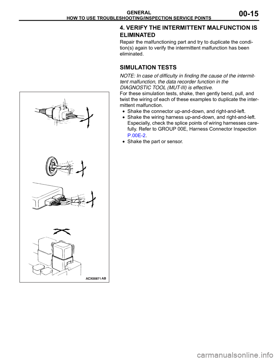
For these simulation tests, shake, then gently bend, pull, and
twist the wiring of each of these examples to duplicate the inter-
mittent malfunction.
Shake the connector up-and-down, and right-and-left.
Shake the wiring harness up-and-down, and right-and-left.
Especially, check the splice points of wiring harnesses care-
fully. Refer to GROUP 00E, Harness Connector Inspection
P.00E-2.
Shake the part or sensor.
Page 1243 of 1500
PRECAUTIONS BEFORE SERVICE
GENERAL00-22
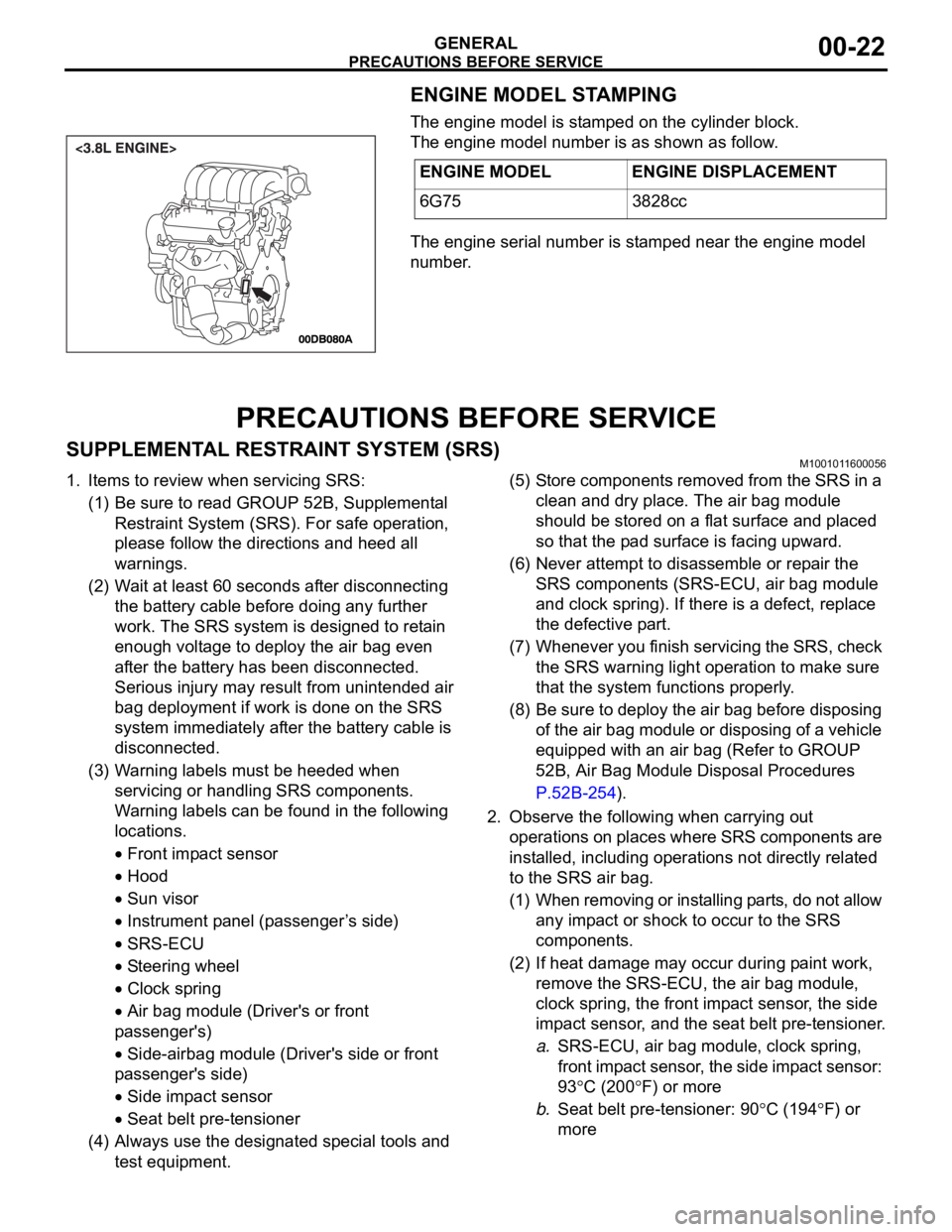
ENGINE MODEL STAMPING
The engine model is stamped on the cylinder block.
The engine model number is as shown as follow.
The engine serial number is stamped near the engine model
number.
PRECAUTIONS BEFORE SERVICE
SUPPLEMENTAL RESTRAINT SYSTEM (SRS)M1001011600056
1. Items to review when servicing SRS:
(1) Be sure to read GROUP 52B, Supplemental
Restraint System (SRS). For safe operation,
please follow the directions and heed all
warnings.
(2) Wait at least 60 seconds after disconnecting
the battery cable before doing any further
work. The SRS system is designed to retain
enough voltage to deploy the air bag even
after the battery has been disconnected.
Serious injury may result from unintended air
bag deployment if work is done on the SRS
system immediately after the battery cable is
disconnected.
(3) Warning labels must be heeded when
servicing or handling SRS components.
Warning labels can be found in the following
locations.
Front impact sensor
Hood
Sun visor
Instrument panel (passenger ’s side)
SRS-ECU
Steering wheel
Clock spring
Air bag module (Driver's or front
passenger's)
Side-airbag module (Driver's side or front
passenger's side)
Side impact sensor
Seat belt pre-tensioner
(4) Always use the designated special tools and
test equipment.(5) Store components removed from the SRS in a
clean and dry place. The air bag module
should be stored on a flat surface and placed
so that the pad surface is facing upward.
(6) Never attempt to disassemble or repair the
SRS components (SRS-ECU, air bag module
and clock spring). If there is a defect, replace
the defective part.
(7) Whenever you finish servicing the SRS, check
the SRS warning light operation to make sure
that the system functions properly.
(8) Be sure to deploy the air bag before disposing
of the air bag module or disposing of a vehicle
equipped with an air bag (Refer to GROUP
52B, Air Bag Module Disposal Procedures
P.52B-254).
2. Observe the following when carrying out
operations on places where SRS components are
installed, including operations not directly related
to the SRS air bag.
(1) When removing or installing parts, do not allow
any impact or shock to occur to the SRS
components.
(2) If heat damage may occur during paint work,
remove the SRS-ECU, the air bag module,
clock spring, the front impact sensor, the side
impact sensor, and the seat belt pre-tensioner.
a.SRS-ECU, air bag module, clock spring,
front impact sensor, the side impact sensor:
93
C (200F) or more
b.Seat belt pre-tensioner: 90
C (194F) or
more ENGINE MODEL ENGINE DISPLACEMENT
6G75 3828cc
Page 1246 of 1500
PRECAUTIONS BEFORE SERVICE
GENERAL00-25
APPLICATION OF ANTI-CORROSION AGENTS
AND UNDERCOATS
M1001011000043
Do not to apply oil or grease to the heated oxygen sensor. If
applied, the sensor may malfunction. Protect the heated oxy-
gen sensor with a cover before applying anti-corrosion agent,
etc.
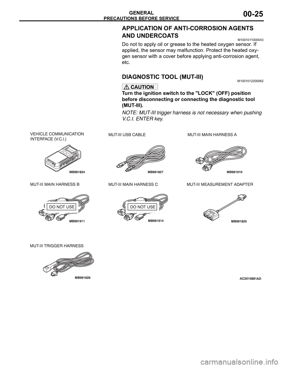
DIAGNOSTIC TOOL (MUT-III)M1001012200062
Turn the ignition switch to the "LOCK" (OFF) position
before disconnecting or connecting the diagnostic tool
(MUT-III).
NOTE: MUT-III trigger harness is not necessary when pushing
V.C.I. ENTER key.
Page 1255 of 1500
LUBRICATION AND MAINTENANCE
GENERAL00-34
LUBRICATION AND MAINTENANCEM1001001200336
Maintenance and lubrication service recommenda-
tions have been compiled to provide maximum pro-
tection for the vehicle owner's investment against all
reasonable types of driving conditions. Since these
conditions vary with the individual vehicle owner's
driving habits, the area in which the vehicle is oper-
ated and the type of driving to which the vehicle is
subjected, it is necessary to prescribe lubrication and
maintenance service on a time frequency as well as
mileage interval basis.
Oils, lubricants and greases are classified and
graded according to standards recommended by the
Society of Automotive Engineers (SAE) and the Aus-
tralian Petroleum Institute (API).
MAINTENANCE SCHEDULES
For Information on service maintenance refer to the
"Service handbook".
ENGINE OIL
Tests have shown that laboratory animals
develop skin cancer after prolonged contact with
used engine oil. Accordingly, the potential exists
for humans to develop a number of skin disor-
ders, including cancer, from such exposure to
used engine oil. Therefore, when changing
engine oil, be careful not to touch it as much as
possible. Protective clothing and gloves, that
cannot be penetrated by oil, should be worn. The
skin should be thoroughly washed with soap and
water, or use waterless hand cleaner, to remove
any used engine oil. Do not use petrol, thinners,
or solvents.Either of the following engine oils should be used:
1. Engine oil conforming to the ACEA classification:
"For service A1, A2 or A3.
2. Engine oil conforming to the API classification:
"For service SG" or higher.
FUEL USAGE STATEMENT
Using leaded petrol in this car will damage the
catalytic converters and heated oxygen sensors,
and affect the warranty coverage validity.
This vehicle must use unleaded petrol only.
This vehicle has a fuel filler tube which is especially
designed to accept only the smaller-diameter
unleaded petrol dispensing nozzle.
The 3.8L model is designed to operate on unleaded
petrol having an octane rating (DIN 51607) of 90
RON or higher.
.
PETROL CONTAINING ALCOHOL
Some petrol sold at service stations contain alcohol
although they may not be so identified.
Using fuels containing alcohol is not recommended
unless the nature of the blend can be determined as
being satisfactory, as follows.
Gasohol: A mixture of 10% ethanol and 90%
unleaded gasoline may be used in your vehicle. If
driveability problems are experienced as a result of
using gasohol, it is recommended that the vehicle be
operated on petrol.
Methanol: Do not use petrol containing methanol
(wood alcohol). Using this type of alcohol can result
in vehicle performance deterioration and damage
critical parts in the fuel system components. Fuel
system damage and performance problems resulting
from the use of petrol containing methanol may not
be covered by the new vehicle warranty.
MATERIALS ADDED TO FUEL
Indiscriminate use of fuel system cleaning agents
should be avoided. Many materials intended for gum
and varnish removal may contain highly active sol-
vents or similar ingredients that can be harmful to
gasket and diaphragm materials used in fuel system
component parts.
Page 1273 of 1500

MAINTENANCE SERVICE
GENERAL00-52
FRONT IMPACT SENSORS
1. Check that the arrows on the sensors face toward the front
of the vehicle.
The SRS may not activate if a front impact sensor
is not installed properly, which could result in seri-
ous injury or death to the vehicle's driver and pas-
senger.
If a dent, crack, deformation or rust is detected,
replace with a new sensor.
2. Check the front side member and front impact sensor for
deformation or rust.
3. Check the front impact sensor wiring harness for binding;
Check the connector for damage; and check the terminals
for deformation.
Replace the sensor and/or wiring harness if they fail the
visual check (Refer to GROUP 52B, SRS Service
Precautions P.52B-16 and GROUP 52B, Front Impact
Sensor P.52B-231).
SIDE IMPACT SENSORS
If the side impact sensor is not installed securely
and correctly, the side-air bag may not operate
normally.
If a dent, crack, deformation or rust is detected,
replace with a new sensor.
1. Check the side impact sensor and bracket for dents, cracks
or deformation. The side impact sensors are located inside
the center pillars (LH/RH).
2. Check the connector for damage, and terminal for
deformation.
3. Check that there is no bending or corrosion in the center
pillars (LH/RH).
Replace the side impact sensor if it fails the visual check
(Refer to GROUP 52B, Side Impact Sensor P.52B-247).
NOTE: The illustration shows the left side impact sensor (RH).
The position of the other side impact sensor (LH) is symmetri-
cal to this.