Page 892 of 1500
SENSOR
COMPONENT LOCATIONS70-13
Page 920 of 1500
Page 935 of 1500
Page 950 of 1500

THERMOSTAT
ENGINE COOLING14-35
THERMOSTAT
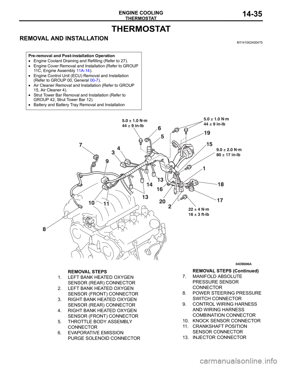
REMOVAL AND INSTALLATIONM1141002400475
Pre-removal and Post-installation Operation
Engine Coolant Draining and Refilling (Refer to 27).
Engine Cover Removal and Installation (Refer to GROUP
11C, Engine Assembly 11A-14).
Engine Control Unit (ECU) Removal and Installation
(Refer to GROUP 00, General 00-7).
Air Cleaner Removal and Installation (Refer to GROUP
15, Air Cleaner 4).
Strut Tower Bar Removal and Installation (Refer to
GROUP 42, Strut Tower Bar 12).
Battery and Battery Tray Removal and Installation
REMOVAL STEPS
1. LEFT BANK HEATED OXYGEN
SENSOR (REAR) CONNECTOR
2. LEFT BANK HEATED OXYGEN
SENSOR (FRONT) CONNECTOR
3. RIGHT BANK HEATED OXYGEN
SENSOR (REAR) CONNECTOR
4. RIGHT BANK HEATED OXYGEN
SENSOR (FRONT) CONNECTOR
5. THROTTLE BODY ASSEMBLY
CONNECTOR
6. EVAPORATIVE EMISSION
PURGE SOLENOID CONNECTOR7. MANIFOLD ABSOLUTE
PRESSURE SENSOR
CONNECTOR
8. POWER STEERING PRESSURE
SWITCH CONNECTOR
9. CONTROL WIRING HARNESS
AND WIRING HARNESS
COMBINATION CONNECTOR
10. KNOCK SENSOR CONNECTOR
11. CRANKSHAFT POSITION
SENSOR CONNECTOR
13. INJECTOR CONNECTORREMOVAL STEPS (Continued)
Page 951 of 1500
Page 954 of 1500
WATE R P U M P
ENGINE COOLING14-39
WAT E R P U M P
REMOVAL AND INSTALLATIONM1141002700498
INSTALLATION SERVICE POINT
.
>>A<< O-RING INSTALLATION
Do not let the O-ring get contaminated with grease or
engine oil.
Fit the O-ring into the groove of the water pipe ends, and apply
water or coolant to the circumference of the O-ring and the pipe
bores to insert the pipe assembly.
Pre-removal and Post-installation Operation
Engine Coolant Draining and Refilling (Refer to 27).
Timing Belt Removal and Installation (Refer to GROUP
11C, Timing Belt 11A-46).
Crankshaft Position Sensor Removal and Installation
(Refer to GROUP 16, Crankshaft Position Sensor 35).
REMOVAL STEPS
1. WATER PUMP BRACKET
2. WATER PUMP3. WATER PUMP GASKET
>>A<<4. O-RINGREMOVAL STEPS (Continued)
Page 955 of 1500
Page 956 of 1500
WATER HOSE AND WATER PIPE
ENGINE COOLING14-41
INSTALLATION SERVICE POINTS
.
>>A<< O-RING INSTALLATION
Do not allow engine oil or other grease to adhere to the
O-ring
Insert the O-ring to the water pipe, and coat the outer portion of
the O-ring with water or engine coolant.
.
>>B<< ENGINE COOLANT TEMPERATURE
SENSOR INSTALLATION
Apply the specified sealant to the thread of the engine coolant
temperature sensor, and then tighten it to the specified torque.
Specified Sealant: 3M
AAD Part No. 8731 or equiva-
lent
.
>>C<< RADIATOR UPPER HOSE CONNECTION
1. Insert each hose as far as the projection of the water outlet
fitting.
2. Align the mating marks on the radiator hose and hose
clamp, and then connect the radiator hose.
INSPECTIONM1141003400337.
Water Pipe and Hose Check
Check the water pipe and hose for cracks, damage and clogs.
Replace them if necessary.