Page 1009 of 1500

IGNITION SYSTEM
ENGINE ELECTRICAL16-32
SPARK PLUG TESTM1163001500143
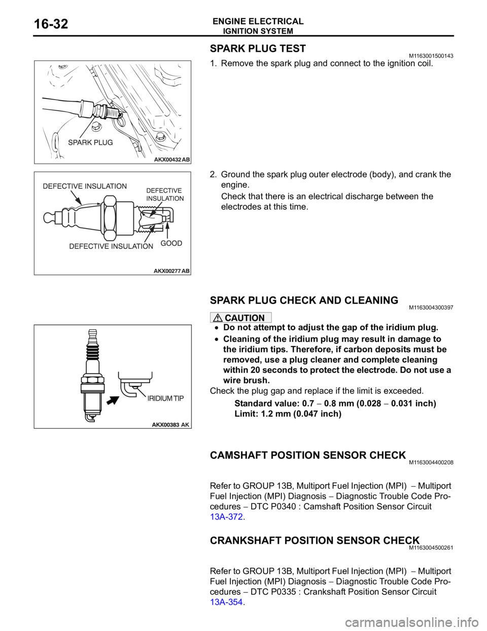
1. Remove the spark plug and connect to the ignition coil.
2. Ground the spark plug outer electrode (body), and crank the
engine.
Check that there is an electrical discharge between the
electrodes at this time.
SPARK PLUG CHECK AND CLEANING M1163004300397
Do not attempt to adjust the gap of the iridium plug.
Cleaning of the iridium plug may result in damage to
the iridium tips. Therefore, if carbon deposits must be
removed, use a plug cleaner and complete cleaning
within 20 seconds to protect the electrode. Do not use a
wire brush.
Check the plug gap and replace if the limit is exceeded.
Standard value: 0.7
0.8 mm (0.028 0.031 inch)
Limit: 1.2 mm (0.047 inch)
CAMSHAFT POSITION SENSOR CHECKM1163004400208
Refer to GROUP 13B, Multiport Fuel Injection (MPI) Multiport
Fuel Injection (MPI) Diagnosis
Diagnostic Trouble Code Pro-
cedures
DTC P0340 : Camshaft Position Sensor Circuit
13A-372.
CRANKSHAFT POSITION SENSOR CHECKM1163004500261
Refer to GROUP 13B, Multiport Fuel Injection (MPI) Multiport
Fuel Injection (MPI) Diagnosis
Diagnostic Trouble Code Pro-
cedures
DTC P0335 : Crankshaft Position Sensor Circuit
13A-354.
Page 1011 of 1500
IGNITION SYSTEM
ENGINE ELECTRICAL16-34
CAMSHAFT POSITION SENSOR
REMOVAL AND INSTALLATION M1163003400476
REMOVAL STEPS
1. CAMSHAFT POSITION SENSOR
CONNECTOR2. CAMSHAFT POSITION SENSOR
3. O-RINGREMOVAL STEPS (Continued)
Page 1012 of 1500
IGNITION SYSTEM
ENGINE ELECTRICAL16-35
CRANKSHAFT POSITION SENSOR
REMOVAL AND INSTALLATION M1163003500473
Pre-removal and Post-installation Operation
Timing Belt Lower Cover Removal and Installation (Refer to
GROUP 11C, Timing Belt 11A-46).
Page 1013 of 1500
Page 1014 of 1500
IGNITION SYSTEM
ENGINE ELECTRICAL16-37
INSTALLATION SERVICE POINT
.
>>A<< KNOCK SENSOR INSTALLATION
Use special tool MD998773 to install the knock sensor.
Page 1015 of 1500

SPECIFICATIONS
ENGINE ELECTRICAL16-38
SPECIFICATIONS
FASTENER TIGHTENING SPECIFICATIONSM1161002100506
GENERAL SPECIFICATIONSM1161000200411
ITEM SPECIFICATION
Charging system
Alternator bracket bolt49
9 Nm (36 7 ft-lb)
Alternator bolt49
9 Nm (36 7 ft-lb)
Alternator terminal nut12
2 Nm (102 22 in-lb)
Ignition system
Camshaft position sensor bolt 11
1 Nm (98 8 in-lb)
Crankshaft position sensor bolt 9.0
1.0 Nm (80 9 in-lb)
Ignition coil bolt 10
2 Nm (89 17 in-lb)
Knock sensor 23
2 Nm (17 1 ft-lb)
Spark plug 25
4 Nm (18 3 ft-lb)
Starting system
Starter bolt 30
3 Nm (23 2 ft-lb)
Starter cover bolt 4.9
1.0 Nm (44 8 in-lb)
Starter terminal nut 12
2 Nm (102 22 in-lb)
ITEMS SPECIFICATIONS
Alternator
Type Positive battery positive voltage sensing
Identification number
Part No. MN180394
Rated output V/A 12/110
Voltage regulator Electronic built-in type
Starter Motor
Type Reduction drive with planetary gear
Identification number M000T31172
Part No. 1810A090
Rated output kW/V 1.2/12
Number of pinion teeth 8
Ignition Coil
Type Molded 6 coil
Spark Plugs
BOSCH FR8DI30
Page 1166 of 1500

35A-1
GROUP 35A
BASIC BRAKE
SYSTEM
CONTENTS
GENERAL DESCRIPTION. . . . . . . . .35A-2
BASIC BRAKE SYSTEM DIAGNOSIS35A-3
INTRODUCTION TO BASIC BRAKE
SYSTEM DIAGNOSIS . . . . . . . . . . . . . . . . 35A-3
BASIC BRAKE SYSTEM DIAGNOSTIC
TROUBLESHOOTING STRATEGY . . . . . . 35A-3
SYMPTOM CHART. . . . . . . . . . . . . . . . . . . 35A-3
SYMPTOM PROCEDURES . . . . . . . . . . . . 35A-3
SPECIAL TOOLS . . . . . . . . . . . . . . . .35A-12
ON-VEHICLE SERVICE . . . . . . . . . . .35A-13
BRAKE PEDAL CHECK AND
ADJUSTMENT . . . . . . . . . . . . . . . . . . . . . . 35A-13
BRAKE BOOSTER OPERATING TEST . . . 35A-14
CHECK VALVE OPERATION CHECK . . . . 35A-15
BLEEDING . . . . . . . . . . . . . . . . . . . . . . . . . 35A-16
BRAKE FLUID LEVEL SENSOR CHECK. . 35A-17
DISC BRAKE PAD CHECK AND
REPLACEMENT . . . . . . . . . . . . . . . . . . . . . 35A-17
DISC BRAKE ROTOR CHECK . . . . . . . . . . 35A-19
MASTER CYLINDER FUNCTION CHECK . 35A-23
BRAKE PEDAL. . . . . . . . . . . . . . . . . .35A-24
REMOVAL AND INSTALLATION . . . . . . . . 35A-24
INSPECTION. . . . . . . . . . . . . . . . . . . . . . . . 35A-25
MASTER CYLINDER ASSEMBLY
AND BRAKE BOOSTER . . . . . . . . . .35A-26
REMOVAL AND INSTALLATION . . . . . . . . 35A-26
MASTER CYLINDER . . . . . . . . . . . . . . . . . 35A-28
INSPECTION. . . . . . . . . . . . . . . . . . . . . . . . 35A-29
DISC BRAKE ASSEMBLY . . . . . . . . .35A-30
REMOVAL AND INSTALLATION . . . . . . . . 35A-30
INSPECTION. . . . . . . . . . . . . . . . . . . . . . . . 35A-32
DISASSEMBLY AND ASSEMBLY
. . . . . . . . . . . . . . . . . . . . . . . . . . 35A-33
DISASSEMBLY AND ASSEMBLY 35A-36
INSPECTION. . . . . . . . . . . . . . . . . . . . . . . . 35A-38
SPECIFICATIONS . . . . . . . . . . . . . . .35A-40
FASTENER TIGHTENING
SPECIFICATIONS. . . . . . . . . . . . . . . . . . . . 35A-40
GENERAL SPECIFICATIONS . . . . . . . . . . 35A-40
SERVICE SPECIFICATIONS . . . . . . . . . . . 35A-41
LUBRICANTS . . . . . . . . . . . . . . . . . . . . . . . 35A-41
Page 1182 of 1500
ON-VEHICLE SERVICE
BASIC BRAKE SYSTEM35A-17
BRAKE FLUID LEVEL SENSOR CHECKM1351009100403
The brake fluid level sensor is in good condition if there is no
continuity when the float surface is above "MIN" and if there is
continuity when the float surface is below "MIN".
DISC BRAKE PAD CHECK AND REPLACEMENTM1351002300398
NOTE: Uneven wearor tapering of brake pad may be caused
by either caliper piston not operating correctly .
Whenever a pad must be replaced, replace both LH and
RH wheel pads as a set to prevent the vehicle from pull-
ing to one side when braking.
If there is a significant difference in the thicknesses of
the pads on the left and right sides, check the sliding
condition of the piston and slide pins.
1. Check the brake pad thickness through the caliper body
check port.(Rear). Front pad check can be viewed from rotor
side.
Standard value: 10.0 mm (0.39 inch)
Minimum limit: 2.0 mm (0.08 inch)