2005 MITSUBISHI 380 manual transmission
[x] Cancel search: manual transmissionPage 848 of 1500

ON-VEHICLE SERVICE
HEATER, AIR CONDITIONING AND VENTILATION55-147
TEST PROCEDURES
1. Select a quiet area for testing.
2. Duplicate problem (customer complaint) as much as
possible.
3. Judge if the noise is abnormal (ie. it is important to
understand the characteristics of the vehicle and its normal
state to judge what is abnormal) - Compare with similar
vehicle if necessary.
4. Detail what and how noise occurs.
5. Find the noise source and verify its transmission by isolating
the subject part from the vehicle.
6. Repair the problem.
7. Explain and report your findings.
DETAILS OF A/C NOISE
POSSIBLE CAUSES, CHECKS AND REPAIRS
NOISE DESCRIPTION WHEN IT OCCURS SOURCE OF NOISE
Rumbling (Bearing noise) With A/C On or Off Magnetic clutch, idler pulley
Clang-Clack noise When compressor is engaged Magnetic clutch operation
Squawking (Belt sliding noise) When compressor is engaged V-belt
Whistling or Whooping noise Immediately after the A/C is
engaged.Expansion valve
Hissing or swishing noise When A/C is engaged, but
decreases as flow is stable Refrigerant flow
Rattling (Internal compressor) When compressor is operating Compressor internal part
Wooing (Resonant noise) With A/C On, occurs at certain
speed.Resonance of accessories
Cooing (Discharge pulsation
noise)With A/C On or Off Resonating noise with the vehicle
body
NOISE DESCRIPTION POSSIBLE CAUSE CHECK REPAIR
Rumbling (Bearing
noise)Bearing damage in rotor Manual rotation of bearing Replace compressor
Rotor slipping on boss Wear on compressor boss
surfaceReplace compressor
Bearing damage in pulley Check alignment between
pulleysReplace compressor
Clang-Clack noise Hub to stator misaligned Wear on inner clutch face Replace compressor
Gap between clutch
surface is too largeCheck Air gap is within
specificationReplace compressor
Squawking (Belt sliding
noise)Oil/water between the belt
and rotor surfaceOil and water
contaminationClean
Low belt tension Belt tension Reset or Replace belt and
set tension to correct
specification
Whistling or Whooping
noiseVibration of expansion
valveExpansion valve Replace TX valve
Page 1167 of 1500

GENERAL DESCRIPTION
BASIC BRAKE SYSTEM35A-2
GENERAL DESCRIPTIONM1351000100440
The brake system has been designed to give greater
reliability and durability and to provide excellent brak-
ing performance.
FEATURES
.
Improved braking performance
1. An 8+9 inch tandem brake booster provides suffi-
cient braking force in sudden braking range.
2. 296mm front ventilated disc brakes provide sta-
ble braking force and improved braking feel.
3. 303mm rear ventillated disc brakes are used.
.
Improved stability
1. A 4-wheel anti-lock braking system (4ABS) pre-
vents slipping caused by the vehicle wheels lock-
ing up, in order to maintain a stable vehicle
posture and steering performance.
2. An electronic brake-force distribution (EBD)
makes it possible to maintain the maximum
amount of braking force even when the vehicle's
load is unevenly distributed. 3. Front- and rear-wheel X-type brake line layout
are used.
4. Ventilated discs brakes improve anti-fading per-
formance.
.
Improved serviceability
1. A diagnosis function for the ABS system makes
inspection easier.
2. An outer disc separated hub and rotor make
removal and installation easier.
3. The master cylinder reservoir is utilised for both
brake and clutch fluid on manual transmission
vehicles.
4. The master cylinder filter is coloured black for
improved viewing.
5. The ABS-ECU and hydraulic unit are integrated
to make them more compact and light weight.
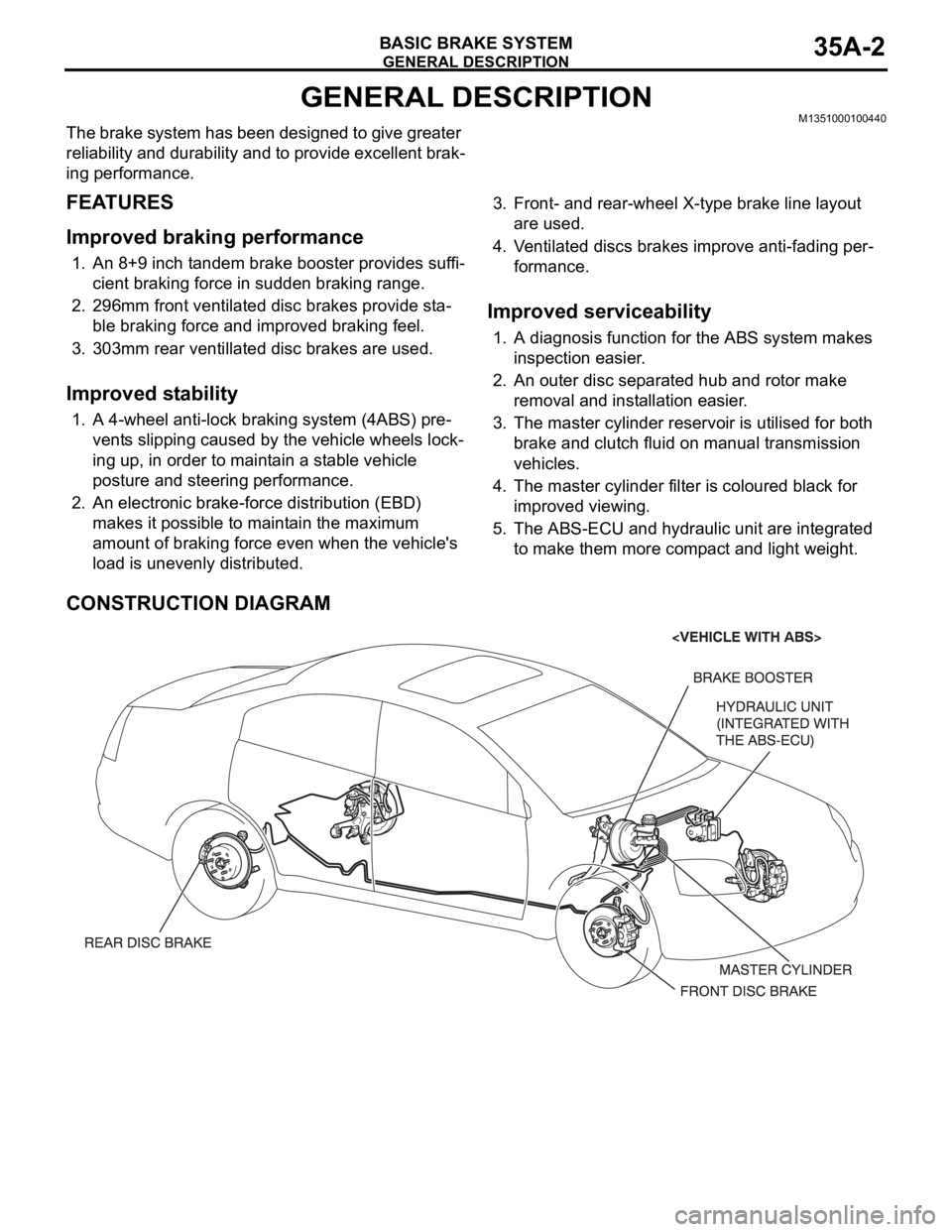
CONSTRUCTION DIAGRAM
Page 1224 of 1500

HOW TO USE THIS MANUAL
GENERAL00-3
HOW TO USE THIS MANUALM1001000100897
MAINTENANCE, REPAIR AND
SERVICING EXPLANATIONS
This manual provides explanations, etc. concerning
procedures for the inspection, maintenance, repair
and servicing of the subject model. Unless otherwise
specified, each service procedure covers all models.
Procedures covering specific models are identified
by the model codes, or similar designation (engine
type, transaxle type, etc). A description of these des-
ignations is covered in this manual under "VEHICLE
IDENTIFICATION."
.
ON-VEHICLE SERVICE
The "ON-VEHICLE SERVICE" section has proce-
dures for performing inspections and adjustments of
particularly important components. These proce-
dures are done with regard to maintenance and ser-
vicing, but other inspections (looseness, play,
cracking, damage, etc.) must also be performed.
.
SERVICE PROCEDURES
The service steps are arranged in numerical order.
Attention to be paid in performing vehicle service are
described in detail in SERVICE POINTS.
DEFINITION OF TERMS
.
STANDARD VALUE
Indicates the value used as the standard for judging
whether or not a part or adjustment is correct.
.
LIMIT
Shows the maximum or minimum value for judging
whether or not a part or adjustment is acceptable.
.
REFERENCE VALUE
Indicates the adjustment value prior to starting the
work (presented in order to facilitate assembly and
adjustment procedures, and so they can be com-
pleted in a shorter time).
.
DANGER, WARNING, AND CAUTION
DANGER, WARNING, and CAUTION call special
attention to a necessary action or to an action that
must be avoided. The differences among DANGER,
WARNING, and CAUTION are as follows:
If a DANGER is not followed, the result is severe
bodily harm or even death.
If a WARNING is not followed, the result could be
bodily injury.
If a CAUTION is not followed, the result could be
damage to the vehicle, vehicle components or
service equipment.
TIGHTENING TORQUE INDICATION
The tightening torque indicates a median and its tol-
erance by a unit of N
m (in-lb.) or Nm (ft.-lb.). For
fasteners with no assigned torque value, refer to
P.00-32.
SPECIAL TOOL NOTE
Only MMC special tool part numbers are called out in
the repair sections of this manual. Please refer to the
special tool cross-reference chart located at the
beginning of each group, for the special tool number
that is available in your market.
ABBREVIATIONS
The following abbreviations are used in this manual
for classification of model types:
A/T:Automatic transaxle, or models equipped with
automatic transaxle.
MPI: Multipoint fuel injection, or engines equipped
with multiport fuel injection.
A/C: Air conditioning.
3.8L engine: 3.8 litre <6G75> engine, or a model
equipped with such an engine.
ABS: Anti-lock Braking System
TCL: Traction Control System
ECU: Electronic Control Unit
V.C.I.: Vehicle Communication Interface
SWS: Simplified Wiring System
CAN: Controller Area Network
M/T: Manual Transmission
SRS: Supplemental Restraint System
Page 1239 of 1500

VEHICLE IDENTIFICATION
GENERAL00-18
VEHICLE IDENTIFICATION
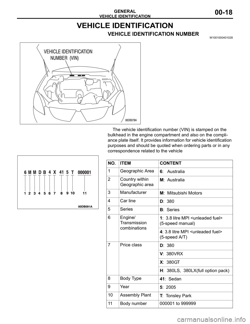
VEHICLE IDENTIFICATION NUMBERM1001000401028
The vehicle identification number (VIN) is stamped on the
bulkhead in the engine compartment and also on the compli-
ance plate itself. It provides information for vehicle identification
purposes and should be quoted when ordering parts or in any
correspondence related to the vehicle
NO. ITEM CONTENT
1 Geographic Area
6: Australia
2 Country within
Geographic areaM: Australia
3 Manufacturer
M: Mitsubishi Motors
4 Car line
D: 380
5Series
B: Series
6 Engine/
Transmission
combinations1: 3.8 litre MPI
(5-speed manual)
4: 3.8 litre MPI
(5-speed A/T)
7Price class
D: 380
V: 380VRX
X: 380GT
H: 380LS, 380LX(full option pack)
8 Body Type
41: Sedan
9Year
5: 2005
10 Assembly Plant
T: Tonsley Park
11 Body number 000001 to 999999
Page 1256 of 1500

RECOMMENDED LUBRICANTS AND LUBRICANT CAPACITIES TABLE
GENERAL00-35
RECOMMENDED LUBRICANTS AND LUBRICANT
CAPACITIES TABLE
M1001001300504
RECOMMENDED LUBRICANTS
LUBRICANT CAPACITY TABLE
<3.8L ENGINE>LUBRICANT SPECIFICATION
Engine oil Engine oils conforming to ACEA A1, A2 or A3 and
AP1 SG or higher
AutomaticTransmission fluid Genuine Mitsubishi Motors ATF-SP III
Manual Transmission fluid Genuine Mitsubishi Motors MTF
Power steering fluid ATF DEXRON III or DEXRON II
Brakes fluid Conforming to DOT 3 or DOT 4
Engine coolant Genuine Mitsubishi Motors coolant
Refrigerant (air conditioning) HFC-134a
DESCRIPTION SPECIFICATION
Engine oil (Litres) Oil pan (excluding oil filter) 4.0
Oil filter 0.3
Engine coolant (Litres) 8.7
Automatic Transmission fluid (Litres) 8.4
Manual Transmission fluid (Litres) 2.8
Power steering fluid (Litres) 1.2
Fuel tank (Litres) 67.0
Washer fluid (Litres) 5.0
Refrigerant (air conditioning) (grams) 435g - 475g
Page 1462 of 1500

GENERAL DESCRIPTION
AUTOMATIC TRANSMISSION23A-3
GENERAL DESCRIPTIONM1231000100366
ITEM SPECIFICATION
Transmission modelF5A5A-4-C5Z
Engine model 6G75-S4-MP
Torque converter Type 3-element, 1-stage, 2-phase type
Lock-up Provided
Stall torque ratio 1.71
Transmission type5 forward speeds, 1 reverse speed, fully automatic
Transmission gear
ratio1st 3.789
2nd 2.162
3rd 1.421
4th 1.000
5th 0.686
Reverse 3.117
Final reduction ratio (Differential gear ratio) 3.325
Clutch Multi-disc type 4 sets
Brake Multi-disc type 2 sets, band type 1 set
Manual control system P-R-N-D (4 position) + Sport mode (up, down)
Shift pattern control Electronic control
Hydraulic control during shifting Electronic control (Each clutch hydraulically independently
controlled)
Torque converter clutch control Electronic control
Transmission fluid Specified lubricants MITSUBISHI ELC4-SP III
Quantity (litres) 8.4
Page 1466 of 1500

GENERAL DESCRIPTION
AUTOMATIC TRANSMISSION23A-7
ELECTRONICALLY-CONTROLLED SYSTEM
.
INVECS-II
When in drive ("D" range), the new automatic transmission
employs an innovative shift schedule to provide a high level
of comfort and "easy driving style" that matches all driving
conditions as well as the driver's driving style.
INVECS-II features "Optimum Shift Control," which provides
shift timing the average driver perceives to be the optimum
timing under any road conditions. "Adaptive Shift Control"
adjusts shift timing to match the driving habits and prefer-
ences of individual drivers.
.
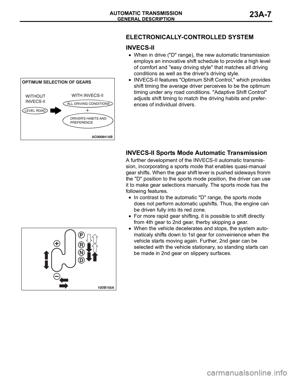
INVECS-II Sports Mode Automatic Transmission
A further development of the INVECS-II automatic transmis-
sion, incorporating a sports mode that enables quasi-manual
gear shifts. When the gear shift lever is pushed sideways fronm
the "D" position to the sports mode position, the driver can use
it to make gear selections manually. The sports mode has the
following features.
In contrast to the automatic "D" range, the sports mode
does not perform automatic upshifts. Thus, the engine can
be driven fully into its red zone.
For more rapid gear shifting, it is possible to shift directly
from 4th gear to 2nd gear, therby skipping a gear.
When the vehicle decelerates and stops, the system auto-
maticaly shifts down to 1st gear for conveinience when the
vehicle starts moving again. Further, 2nd gear can be
selected with the vehicle stationary, so standing starts can
be made in 2nd gear on slippery surfaces.
.
Page 1489 of 1500

AUTOMATIC TRANSMISSION DIAGNOSIS
AUTOMATIC TRANSMISSION23A-30
Only second brake hydraulic
pressure is abnormal.Malfunction of the oil seal G
Malfunction of the oil seal H
Malfunction of the oil seal O
Malfunction of the second solenoid valve
Malfunction of the second pressure control valve
Malfunction of the fail safe valve B
Clogged orifice
Incorrect valve body installation
Malfunction of the accumulator for second brake
Only reduction brake hydraulic
pressure is abnormal.Malfunction of the oil seal U or V
Malfunction of the reduction solenoid valve
Malfunction of the reduction pressure control valve
Clogged orifice
Incorrect valve body installation
Only torque converter pressure
is abnormal.Clogged oil cooler
Malfunction of the oil seal N
Malfunction of the torque converter clutch solenoid
Malfunction of the torque converter pressure control valve
Clogged orifice
Incorrect valve body installation
Pressure applied to element
which should not receive
pressure.Incorrect transmission control cable adjustment
Malfunction of the manual valve
Malfunction of the check ball
Incorrect valve body installation SYMPTOM PROBABLE CAUSE