Page 14 of 1500
SWS DIAGNOSIS
SIMPLIFIED WIRING SYSTEM (SWS)54B-14
6. Remove the steering column cover.
7. Remove the steering column switch connector.
8. Connect special tool MB991812 to the column switch
connector.
9. Connect special tool MB991812 to special tool MB991806.
10.Connect special tool MB991806 to special tool MB991824.
11.Turn the power switch of special tool MB991824 to the "ON"
position.
NOTE: When special tool MB991824 is energised, special
tool MB991824 indicator lamp will be illuminated in a green
color.
12.Start the MUT-III system on the personal computer.
Page 495 of 1500
Page 556 of 1500
ENGINE AND TRANSMISSION
CONFIGURATION DIAGRAMS80-7
B-19 (34) A/T-ECU
B-20 (60) ENGINE-ECU
B-21 (94) ENGINE-ECU
B-22 (26) A/T-ECU
B-24 (4-GR) LEFT BANK HEATED OXYGEN
SENSOR (REAR)
B-25 (4-B) LEFT BANK HEATED OXYGEN
SENSOR (FRONT)
B-26 (2-GR) INJECTOR 6B-27 (2-GR) INJECTOR 4
B-28 (1-B) A/C COMPRESSOR ASSEMBLY
B-29 (1-B) ENGINE OIL PRESSURE SWITCH
B-30 (2-GR) INJECTOR 2
B-31 (1-B) POWER STEERING PRESSURE
SWITCH
B-32 (10-B) CONTROL WIRING HARNESS AND
INJECTOR WIRING HARNESS
COMBINATION
Page 847 of 1500

ON-VEHICLE SERVICE
HEATER, AIR CONDITIONING AND VENTILATION55-146
Sharper bends will reduce the flow of refrigerant. The flexible
hose lines should be routed so that they are at least 80 mm
(3.1 inches) from the exhaust manifold. It is good practice to
inspect all flexible hose lines at least once a year to make sure
they are in good condition and properly routed.
On standard plumbing fittings with O-rings, these O-rings are
not reusable.
AIR CONDITIONING NOISE TEST
You must first know the conditions when the noise occurs.
These conditions are: weather, vehicle speed, in gear or neu-
tral, engine temperature or any other special conditions.
Noises that develop during A/C operation can often be mislead-
ing. For example: what sounds like a failed front bearing or
connecting rod, may be caused by loose bolts, nuts, mounting
brackets, or a loose clutch assembly. Verify accessory drive
belt tension (power steering or generator).
Improper accessory drive belt tension can cause a misleading
noise when the compressor is engaged and little or no noise
when the compressor is disengaged.
Drive belts are speed-sensitive. That is, at different engine
speeds, and depending upon belt tension, belts can develop
unusual noises that are often mistaken for mechanical prob-
lems within the compressor.
Normal air conditioning operation will generate some level of
operational noise. To judge what is normal and abnormal,
requires an understanding of the air conditioning system. This
test is to detail the most common noise complaints and the
repair methods.
VEHICLE CONDITION
1. Ensure the system is not over or under charged.(Refer to
P.55-142).
2. Tighten all compressor mounting bolts, clutch mounting
bolts and compressor drive belt.
3. Inspect layout of the system is correct, ie no interference
between hoses and all retaining clamps are in place.
Page 850 of 1500

ON-VEHICLE SERVICE
HEATER, AIR CONDITIONING AND VENTILATION55-149
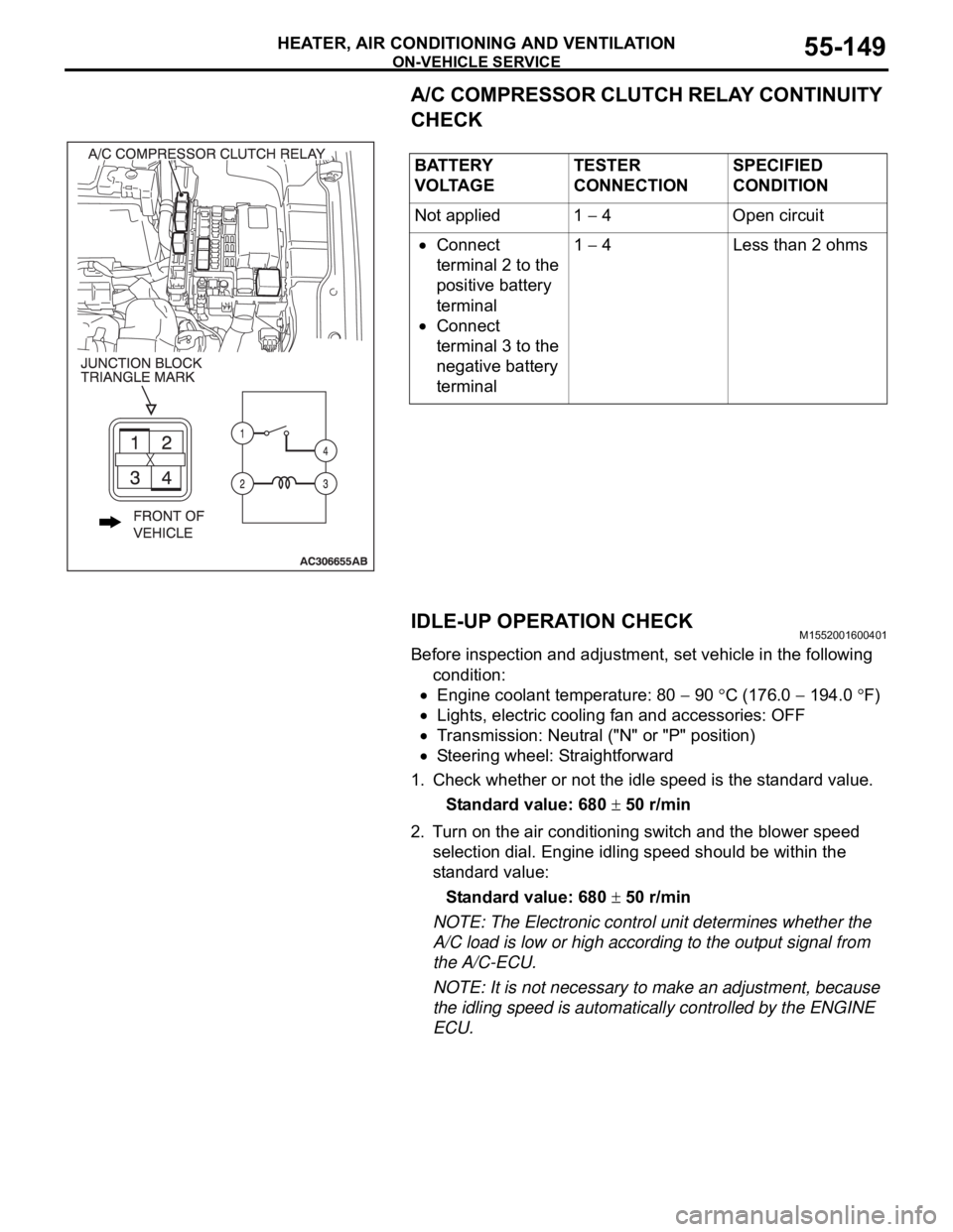
A/C COMPRESSOR CLUTCH RELAY CONTINUITY
CHECK
IDLE-UP OPERATION CHECK
M1552001600401
Before inspection and adjustment, set vehicle in the following
condition:
Engine coolant temperature: 80 90 C (176.0 194.0 F)
Lights, electric cooling fan and accessories: OFF
Transmission: Neutral ("N" or "P" position)
Steering wheel: Straightforward
1. Check whether or not the idle speed is the standard value.
Standard value: 680
50 r/min
2. Turn on the air conditioning switch and the blower speed
selection dial. Engine idling speed should be within the
standard value:
Standard value: 680
50 r/min
NOTE: The Electronic control unit determines whether the
A/C load is low or high according to the output signal from
the A/C-ECU.
NOTE: It is not necessary to make an adjustment, because
the idling speed is automatically controlled by the ENGINE
ECU. BATTERY
V O LTA G ETESTER
CONNECTIONSPECIFIED
CONDITION
Not applied 1
4 Open circuit
Connect
terminal 2 to the
positive battery
terminal
Connect
terminal 3 to the
negative battery
terminal1
4 Less than 2 ohms
Page 852 of 1500

HEATER UNIT, HEATER CORE, BLOWER ASSEMBLY AND EVAPORATOR UNIT
HEATER, AIR CONDITIONING AND VENTILATION55-151
HEATER UNIT, HEATER CORE, BLOWER ASSEMBLY AND
EVAPORATOR UNIT
REMOVAL AND INSTALLATIONM1552021400012
Before removing the front seat assembly, refer to GROUP 52B, Service Precautions
P.52B-16 and Air Bag Module and Clock Spring P.52B-237.
Pre-removal and Post-installation Operation
Refrigerant draining and Refilling (Refer to Charging and
Discharging P.55-142).
Engine coolant Draining and Refilling (Refer to GROUP
00, Engine coolant P.00-47).
Instrument Panel Removal and Installation (Refer to
GROUP 52A, Instrument Panel P.52A-4).
Steering Column Shaft Assembly Removal and Installa-
tion (Refer to GROUP 37A, Steering ShaftP.37-25).
Floor Console Removal and Installation (Refer to GROUP
52A, Floor Console P.52A-10).
Front Seat Assembly Removal and Installation (Refer to
GROUP 52A, Front Seat P.52A-21).
² Strut Tower Bar (Refer to GROUP 42, Removal And
InstallationP.42-12.)
REMOVAL STEPS
BATTERY
AIR CLEANER BODY (REFER TO
GROUP 15, AIR CLEANER
P.15-4.)
1. HEATER HOSE CONNECTION
<>2. SUCTION PIPE CONNECTION
<>3. LIQUID PIPE CONNECTION
4. O-RING
REAR HEATER DUCT A AND B
(REFER TO P.55-175.)
5. JUNCTION BLOCKREMOVAL STEPS (Continued)
Page 868 of 1500
CONDENSER AND CONDENSER FAN
HEATER, AIR CONDITIONING AND VENTILATION55-167
CONDENSER AND CONDENSER FAN
REMOVAL AND INSTALLATIONM1552006700414
Pre-removal and Post-installation Operation
Refrigerant Draining and Refilling (Refer to P.55-142).
Air Duct Removal and Installation (Refer to GROUP 15,
Air Cleaner P.15-4).
Radiator Grilles Removal and Installation (Refer to
GROUP 51, Radiator Grilles P.51-6).
Front End Structure Bar Removal and Installation (Refer
to GROUP 14, Radiator P.14-32).
Cooler tube removal (Refer to GROUP 37, Power steering
P.37-45).
CONDENSER REMOVAL STEPS
<>1. FLEXIBLE DISCHARGE HOSE
CONNECTION
<>2. LIQUID PIPE A CONNECTION3. O-RING
>>B<<4. CONDENSER ASSEMBLY
5. RECEIVER CONDENSER REMOVAL STEPS
Page 897 of 1500
OTHER DEVICES
COMPONENT LOCATIONS70-18
OTHER DEVICESM1701005600302
NAME SYMBOL NAME SYMBOL
Power steering pressure switch A