Page 1020 of 1500
SPECIAL TOOL
POWER PLANT MOUNT32-3
SPECIAL TOOLM1321000600390
TOOL TOOL NUMBER
AND NAMESUPERSESSION APPLICATION
MB991897
Ball joint removerMB991113-01,
MB990635-01 or
General service tool Knuckle and tie rod end ball joint
disconnection
NOTE: Steering linkage puller
(MB990635 or MB991113)is also
used to disconnect the knuckle
and tie rod end ball joint.
Page 1026 of 1500

CROSSMEMBER
POWER PLANT MOUNT32-9
CROSSMEMBER
REMOVAL AND INSTALLATIONM1321003200551
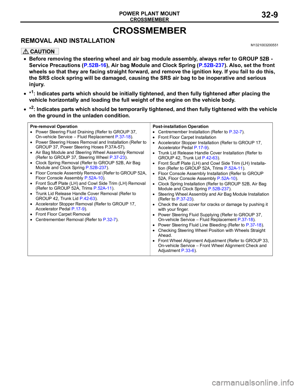
Before removing the steering wheel and air bag module assembly, always refer to GROUP 52B -
Service Precautions (P.52B-16), Air bag Module and Clock Spring (P.52B-237). Also, set the front
wheels so that they are facing straight forward, and remove the ignition key. If you fail to do this,
the SRS clock spring will be damaged, causing the SRS air bag to be inoperative and serious
injury.
*1: Indicates parts which should be initially tightened, and then fully tightened after placing the
vehicle horizontally and loading the full weight of the engine on the vehicle body.
*2: Indicates parts which should be temporarily tightened, and then fully tightened with the vehicle
on the ground in the unladen condition.
Pre-removal Operation
Power Steering Fluid Draining (Refer to GROUP 37,
On-vehicle Service Fluid Replacement P.37-18).
Power Steering Hoses Removal and Installation (Refer to
GROUP 37, Power Steering Hoses P.37A-57).
Air Bag Module and Steering Wheel Assembly Removal
(Refer to GROUP 37, Steering Wheel P.37-23).
Clock Spring Removal (Refer to GROUP 52B, Air Bag
Module and Clock Spring P.52B-237).
Floor Console Assembly Removal (Refer to GROUP 52A,
Floor Console Assembly P.52A-10).
Front Scuff Plate (LH) and Cowl Side Trim (LH) Removal
(Refer to GROUP 52A, Trims P.52A-11).
Trunk Lid Release Handle Cover Removal (Refer to
GROUP 42, Trunk Lid P.42-63).
Accelerator Stopper Removal (Refer to GROUP 17,
Accelerator Pedal P.17-9).
Front Floor Carpet Removal
Centremember Removal (Refer to P.32-7).Post-installation Operation
Centremember Installation (Refer to P.32-7).
Front Floor Carpet Installation
Accelerator Stopper Installation (Refer to GROUP 17,
Accelerator Pedal P.17-9).
Trunk Lid Release Handle Cover Installation (Refer to
GROUP 42, Trunk Lid P.42-63).
Front Scuff Plate (LH) and Cowl Side Trim (LH) Installa-
tion (Refer to GROUP 52A, Trims P.52A-11).
Floor Console Assembly Installation (Refer to GROUP
52A, Floor Console Assembly P.52A-10).
Clock Spring Installation (Refer to GROUP 52B, Air Bag
Module and Clock Spring P.52B-237).
Steering Wheel Assembly and Air Bag Module Installation
(Refer to P.37-23).
Check the dust cover for cracks or damage by pushing it
with your finger.
Power Steering Fluid Supplying (Refer to GROUP 37,
On-vehicle Service Fluid Replacement P.37-18).
Power Steering Fluid Line Bleeding (Refer to P.37-18).
Checking Steering Wheel Position with Wheels Straight
Ahead.
Front Wheel Alignment Adjustment (Refer to GROUP 33,
On-vehicle Service
Front Wheel Alignment Check and
Adjustment P.33-6).
Page 1027 of 1500
Page 1028 of 1500
Page 1030 of 1500
CROSSMEMBER
POWER PLANT MOUNT32-13
<> FRONT AXLE CROSSMEMBER
MOUNTING BOLT REMOVAL
Remove the crossmember mounting bolt.
.
<> ENGINE REAR ROLL STOPPER BRACKET,
POWER STEERING GEAR AND LINKAGE,
STABILIZER BAR AND FRONT AXLE NO.1
CROSSMEMBER ASSEMBLY REMOVAL
Support the front axle number 1 crossmember with a transmis-
sion jack, and then remove the crossmember mounting nuts
and bolts.
INSTALLATION SERVICE POINTS
.
>>A<< STABILIZER BAR INSTALLATION
Align the stabilizer bar identification mark with the right end of
the bushing (LH).
.
Page 1032 of 1500

SPECIFICATIONS
POWER PLANT MOUNT32-15
SPECIFICATIONS
FASTENER TIGHTENING SPECIFICATIONSM1321004100308
ITEM SPECIFICATION
Crossmember
Engine rear roll stopper bracket bolt 58
7 Nm
Front axle crossmember stay bolt and nut 83
12 Nm (61 9 ft-lb)
Front axle No.1 crossmember bolt and nut 180
20 Nm (133 15 ft-lb)
Lower arm assembly bolt 165
15 Nm (122 11 ft-lb)
Lower arm assembly nut (flange nut, self-locking) M14 165
15 Nm (122 11 ft-lb)
Lower arm ball joint clamp assembly nut 110
10 Nm
Power steering gear and linkage bolt 83
12 Nm (61 9 ft-lb)
Power steering gear bracket bolt M12 83
12 Nm (61 9 ft-lb)
Pressure hose clamp bolt and nut 12
2 Nm (102 22 in-lb)
Pressure hose nut 15
3 Nm (11 2 ft-lb)
Return tube clamp bolt and nut 12
2 Nm (102 22 in-lb)
Return tube nut 15
3 Nm (11 2 ft-lb)
Stabilizer bracket bolt 58
7 Nm (43 5 ft-lb)
Stabilizer link nut 48
7 Nm (36 5 ft-lb)
Steering column assembly bolt 18
2 Nm (13 2 ft-lb)
Steering gear and linkage protector bolt 12
2 Nm (102 22 in-lb)
Tie rod end nut 29
4 Nm (21 3 ft-lb)
Engine mounting
Engine mounting thru bolt M12 108
10 Nm (80 9 ft-lb)
Engine front mounting bracket bolt and nut M12 108
10 Nm (80 9 ft-lb)
Engine mounting stay bolt 36
6 Nm (27 4 ft-lb)
Engine roll stopper and centremember
Centremember bolt83
12 Nm (61 9 ft-lb)
Engine front roll stopper thru bolt and nut 69
10 Nm (61 9 ft-lb
Engine rear roll stopper thru bolt and nut 69
10 Nm (61 9 ft-lb
Transaxle case rear roll stopper bracket bolt 90
10 Nm (67 7 ft-lb)
Transaxle mounting
Transaxle mounting body side bracket nut (nut, flange) M12 83
12 Nm (61 9 ft-lb)
Transaxle mounting body side bracket nut (nut, self-locking) M1283
12 Nm (61 9 ft-lb)
Page 1167 of 1500

GENERAL DESCRIPTION
BASIC BRAKE SYSTEM35A-2
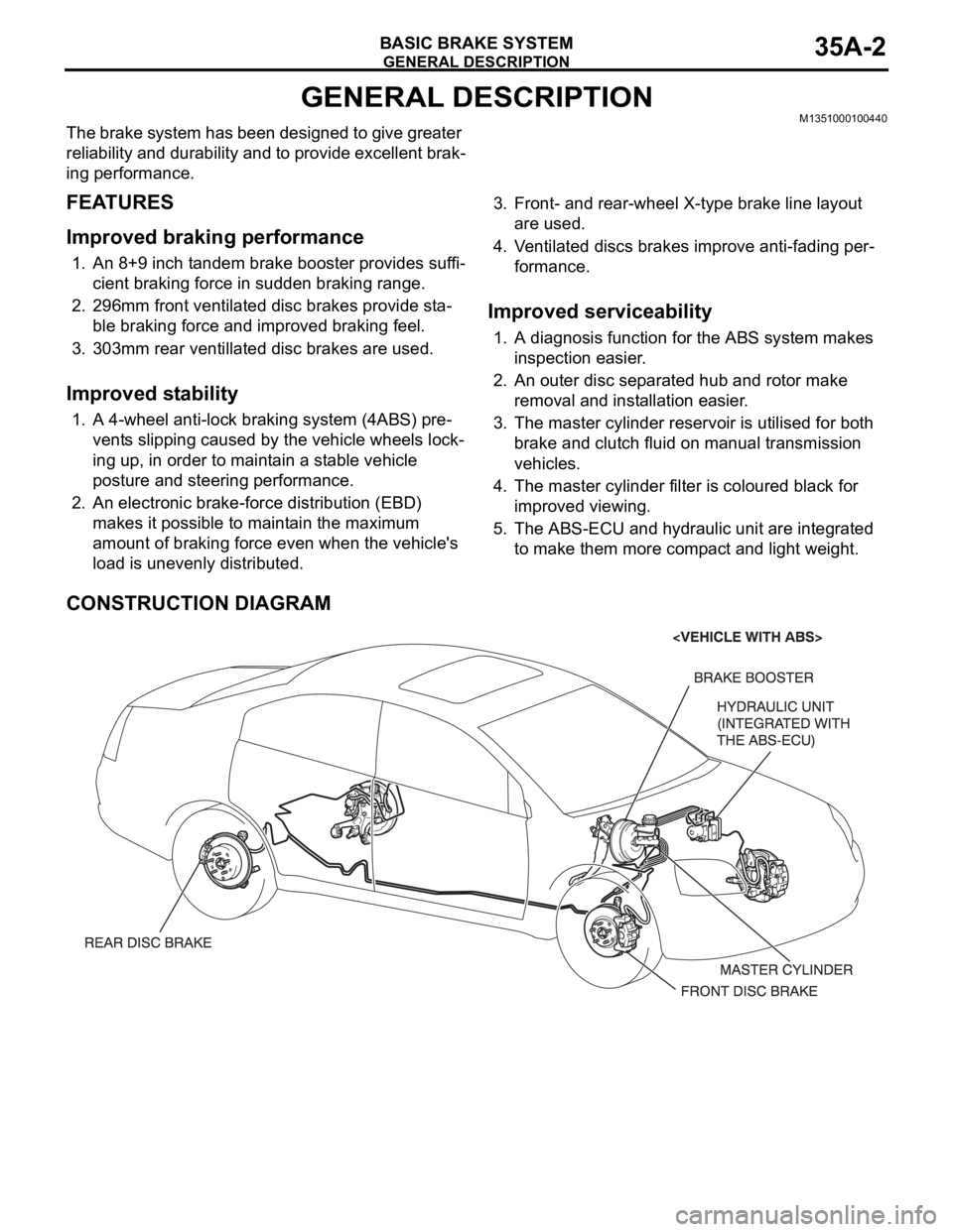
GENERAL DESCRIPTIONM1351000100440
The brake system has been designed to give greater
reliability and durability and to provide excellent brak-
ing performance.
FEATURES
.
Improved braking performance
1. An 8+9 inch tandem brake booster provides suffi-
cient braking force in sudden braking range.
2. 296mm front ventilated disc brakes provide sta-
ble braking force and improved braking feel.
3. 303mm rear ventillated disc brakes are used.
.
Improved stability
1. A 4-wheel anti-lock braking system (4ABS) pre-
vents slipping caused by the vehicle wheels lock-
ing up, in order to maintain a stable vehicle
posture and steering performance.
2. An electronic brake-force distribution (EBD)
makes it possible to maintain the maximum
amount of braking force even when the vehicle's
load is unevenly distributed. 3. Front- and rear-wheel X-type brake line layout
are used.
4. Ventilated discs brakes improve anti-fading per-
formance.
.
Improved serviceability
1. A diagnosis function for the ABS system makes
inspection easier.
2. An outer disc separated hub and rotor make
removal and installation easier.
3. The master cylinder reservoir is utilised for both
brake and clutch fluid on manual transmission
vehicles.
4. The master cylinder filter is coloured black for
improved viewing.
5. The ABS-ECU and hydraulic unit are integrated
to make them more compact and light weight.
CONSTRUCTION DIAGRAM
Page 1223 of 1500

GENERAL00-2
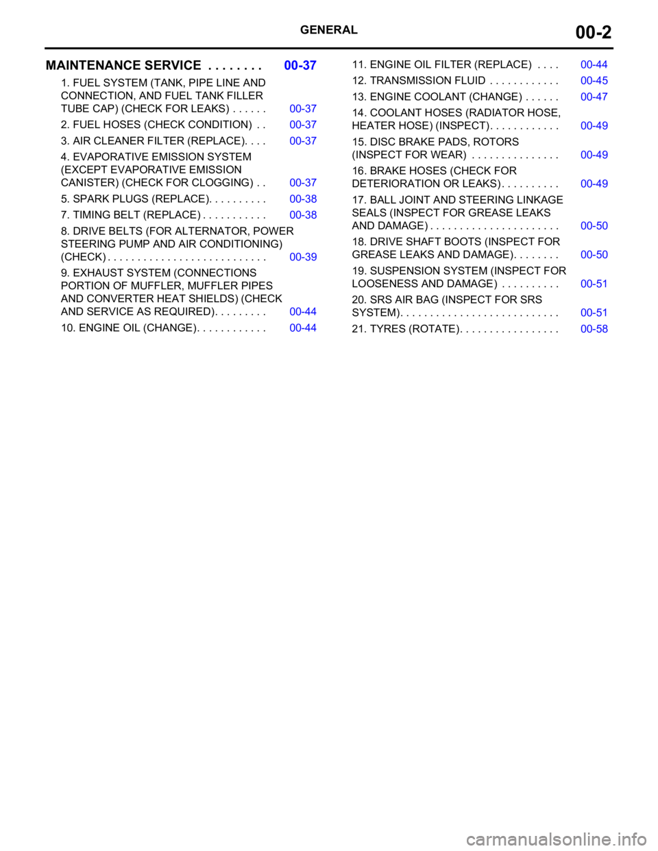
MAINTENANCE SERVICE . . . . . . . .00-37
1. FUEL SYSTEM (TANK, PIPE LINE AND
CONNECTION, AND FUEL TANK FILLER
TUBE CAP) (CHECK FOR LEAKS) . . . . . . 00-37
2. FUEL HOSES (CHECK CONDITION) . . 00-37
3. AIR CLEANER FILTER (REPLACE). . . . 00-37
4. EVAPORATIVE EMISSION SYSTEM
(EXCEPT EVAPORATIVE EMISSION
CANISTER) (CHECK FOR CLOGGING) . . 00-37
5. SPARK PLUGS (REPLACE). . . . . . . . . . 00-38
7. TIMING BELT (REPLACE) . . . . . . . . . . . 00-38
8. DRIVE BELTS (FOR ALTERNATOR, POWER
STEERING PUMP AND AIR CONDITIONING)
(CHECK) . . . . . . . . . . . . . . . . . . . . . . . . . . . 00-39
9. EXHAUST SYSTEM (CONNECTIONS
PORTION OF MUFFLER, MUFFLER PIPES
AND CONVERTER HEAT SHIELDS) (CHECK
AND SERVICE AS REQUIRED) . . . . . . . . . 00-44
10. ENGINE OIL (CHANGE) . . . . . . . . . . . . 00-4411. ENGINE OIL FILTER (REPLACE) . . . . 00-44
12. TRANSMISSION FLUID . . . . . . . . . . . . 00-45
13. ENGINE COOLANT (CHANGE) . . . . . . 00-47
14. COOLANT HOSES (RADIATOR HOSE,
HEATER HOSE) (INSPECT). . . . . . . . . . . . 00-49
15. DISC BRAKE PADS, ROTORS
(INSPECT FOR WEAR) . . . . . . . . . . . . . . . 00-49
16. BRAKE HOSES (CHECK FOR
DETERIORATION OR LEAKS) . . . . . . . . . . 00-49
17. BALL JOINT AND STEERING LINKAGE
SEALS (INSPECT FOR GREASE LEAKS
AND DAMAGE) . . . . . . . . . . . . . . . . . . . . . . 00-50
18. DRIVE SHAFT BOOTS (INSPECT FOR
GREASE LEAKS AND DAMAGE) . . . . . . . . 00-50
19. SUSPENSION SYSTEM (INSPECT FOR
LOOSENESS AND DAMAGE) . . . . . . . . . . 00-51
20. SRS AIR BAG (INSPECT FOR SRS
SYSTEM). . . . . . . . . . . . . . . . . . . . . . . . . . . 00-51
21. TYRES (ROTATE). . . . . . . . . . . . . . . . . 00-58